

دليل اختيار RCBO للدوائر الحقيقية: النوع A/AC، 30mA، منحنيات B/C، والأقطاب
طلب “32 A، 30 mA RCBO” ليس جاهزًا للطلب. فهو يحدد فئة تيار الحمل وعتبة التيار المتبقي، لكنه لا يحدد شكل موجة العطل، أو تيار البدء، أو حد الكابل، أو موصلات التغذية، أو تيار الدائرة القصيرة المتاح. قد يصف الرقمان نفسهما دائرة مقابس عامة، أو مجموعة من محركات LED، أو مغذي عاكس—وقد تحتاج تلك الدوائر إلى قواطع RCBO مختلفة.
الإجابة العملية هي اختيار قاطع RCBO حول مهمة الحماية. للدائرة النهائية الحديثة النموذجية، النوع A و30 mA غالبًا ما يكونان نقطة البداية. الاختيار النهائي يعتمد على ما إذا كان الحمل ينتج تسربًا إلكترونيًا، ما إذا كان منحنى B يمكنه تحمل بدء التشغيل، أي الموصلات يجب فصلها وما إذا كانت 6 kA كافية في اللوحة.
يتبع هذا الدليل ثلاثة ملفات مشاريع بدلاً من تسلسل الكتالوج. يبدأ كل مشروع بمخاطر مختلفة، ثم ينتهي بوصف كامل لقاطع RCBO يمكن للمقاول أو باني اللوحات أو الموزع استخدامه فعليًا.
ثلاث دوائر لا ينبغي أن تتلقى نفس قاطع RCBO
| ملف المشروع | عدم اليقين الرئيسي | نقطة البداية المحتملة | القرار الذي يتحكم في النتيجة |
|---|---|---|---|
| دائرة مقابس المكتب | الأحمال الإلكترونية المستقبلية والاستمرارية | النوع A، 30 mA، قاطع RCBO فردي | تصنيف الكابل، مستوى العطل وواجهة اللوحة |
| إضاءة LED ولوحة مضخة صغيرة | تيار بدء التشغيل القصير | النوع A، 30 mA، منحنى B أو C | تيار الاندفاع المقاس/المعلن مقابل ظروف فصل العطل |
| دائرة ثلاثية الطور مدعومة بعاكس | شكل موجة التيار المتبقي، الطاقة العكسية والمحايد | النوع المحدد بالمعدات A/F/B و3P/3P+N/4P | تعليمات المحول، طوبولوجيا التغذية والموافقة ثنائية الاتجاه |
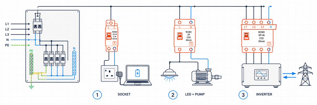
ثلاث دوائر نهائية مختلفة تتطلب اختيار RCBO بناءً على حملها الفعلي وترتيب الموصلاتهذه الأمثلة توضيحية، وليست سجلات لمشاريع JUTRION مكتملة. الغرض منها هو إظهار كيف تتغير معلمة واحدة لأن الدائرة تتغير.
ملف المشروع 1: دائرة مقابس مكتب
الدائرة الأولى تزود مآخذ عامة في مكتب 230 V. اليوم تشمل المعدات المتصلة الحواسيب المحمولة، الشاشات، الشواحن وطابعة. غدًا قد يوصل المستخدمون أجهزة إلكترونية مختلفة. لذلك لا يمكن للمصمم إثبات أن الدائرة ستظل حملاً جيبيًا بسيطًا.
النوع A هو نقطة البداية القابلة للدفاع
النوع AC يستجيب للتيار المتبقي المتناوب الجيبي. النوع A يستجيب أيضًا للتيار المتبقي المستمر النبضي. الإلكترونيات أحادية الطور الحديثة عادة تحتوي على مقومات ومزودات طاقة ذات وضع تبديل، لذا النوع A هو نقطة البداية العملية عادة لدائرة مأخذ غير محددة.
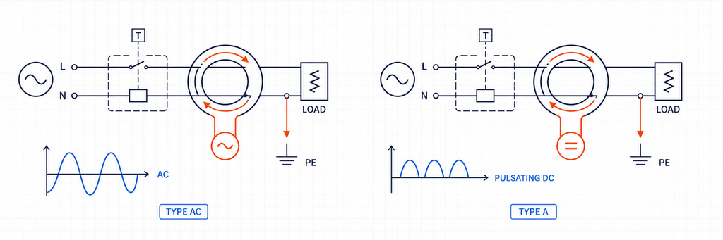
مقارنة شكل موجة التيار المتبقي بين قاطع RCBO من النوع AC والنوع Aالنوع A ليس بديلاً عالميًا لكل أنواع RCD. المعدات القادرة على إنتاج تيارات متبقية مستمرة ناعمة أو مختلطة التردد قد تتطلب النوع F أو النوع B أو ترتيبًا معلنًا آخر. لدائرة مأخذ مكتب عامة، النوع A يعالج حمولة أكثر واقعية من النوع AC.
لماذا 30 mA و20 A تجيبان على أسئلة مختلفة
يقترح مواصفات المكتب تصنيف تيار متبقٍ قدره 30 mA للحماية الإضافية وفقًا لقواعد التركيب المعمول بها. قيمة 30 mA هذه هي IΔn؛ وهي تصف وظيفة التيار المتبقي. ولا تصف تيار الحمل الذي يمكن للدائرة حمله.
افترض أن تيار التصميم المحسوب هو 17.2 A وأن الكابل المركب له قدرة حمل تيار مصححة تبلغ 24 A. يمر جهاز 20 A عبر علاقة حماية الموصل الأولية:
Ib ≤ In ≤ Iz
17.2 A ≤ 20 A ≤ 24 A
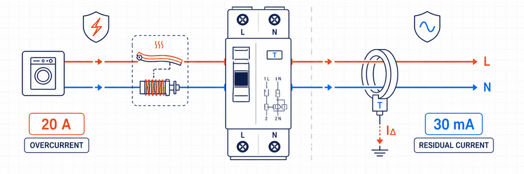
حماية زيادة التيار لقاطع RCBO 20 أمبير مقارنة بحماية التيار المتبقي 30 مللي أمبيرهنا، Ib هو تيار التصميم، وIn هو التيار المقنن لقاطع RCBO، وIz هي قدرة الكابل المصححة. يجب أن تكون درجة الحرارة المحيطة والتجميع والعزل وطريقة التركيب والتوافقيات والقواعد الوطنية منعكسة بالفعل في Iz. اختيار 25 A لأنه الحجم التالي في الكتالوج سيتجاوز قدرة الكابل المذكورة.
RCBOs الفردية تحمي الاستمرارية وكذلك الأشخاص
إذا شاركت عدة دوائر مكتبية RCCB واحد، يتراكم التسرب من فلاترها الإلكترونية عند الجهاز المشترك. قد يؤدي حدث عطل أرضي واحد أيضًا إلى فصل كل MCBs المتفرعة. RCBOs الفردية تقسم التسرب حسب الدائرة وعادة تحتوي على فصل التيار المتبقي للفرع المتأثر. هذا يسهل تحديد العطل ويقلل فقد الخدمة غير الضروري.
لا تلغي هذه البنية تخطيط التسرب. لا يزال التيار الطبيعي لموصل الحماية بحاجة إلى هامش أقل من عتبة الجهاز، خاصةً عند توصيل العديد من مصادر طاقة تكنولوجيا المعلومات أو الكابلات الطويلة.
نتيجة المكتب
230 V AC، قاطع RCBO 1P+N، 20 A، النوع A، 30 mA، منحنى B أو C رهناً بالتحقق من الاندفاع والعطل، قدرة قطع أعلى من مستوى عطل اللوحة المقاس/المحسوب، متوافق مع قضيب ناقل وحدة المستهلك المعلن.
يبقى المنحنى وقدرة القطع مفتوحين لأنه لا يمكن اختيار أي منهما من “مقابس المكتب” وحدها.
ملف المشروع 2: إضاءة LED بجانب مضخة صغيرة
تحتوي اللوحة الثانية على دائرتين صادرتين بتيار طبيعي مماثل. تغذي إحداهما مجموعة من محركات LED؛ وتغذي الأخرى مضخة صغيرة مباشرة على الخط. يمكن لكلتيهما إنتاج ذروة تيار قصيرة أثناء التنشيط، لكن مصدر تلك الذروة ومدتها يختلفان.
منحنى B مقابل منحنى C هو قرار اندفاع ومسار عطل
بالنسبة لخصائص القواطع المصغرة IEC الشائعة، عادةً ما يكون لمنحنى B نطاق تشغيل لحظي حول 3–5 أضعاف In، بينما يكون منحنى C حول 5–10 أضعاف In. منحنى D، غالبًا حول 10–20 ضعف In، مخصص لمهام اندفاع أعلى تم هندستها خصيصًا. يجب التحقق من التشغيل الدقيق مقابل بيانات المنتج المعمول بها.
يمكن لقاطع RCBO بمنحنى C تحمل تيار بدء تشغيل قصير المدة أكبر قبل أن يعمل عنصره المغناطيسي. وهذا لا يجعله خيارًا أفضل للأغراض العامة. كما أن العتبة الأعلى تعني أن الدائرة يجب أن توفر تيار عطل أكبر لضمان الفصل اللحظي.
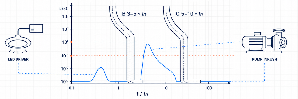
مقارنة نطاقات الفصل اللحظي لقاطع RCBO بمنحنى B ومنحنى C مع تيار اندفاع محرك LED والمضخة| أدلة من الدائرة | ماذا يقترح | ما الذي يجب التحقق منه بعد ذلك |
|---|---|---|
| ذروة بدء منخفضة أو محكومة | قد تظل منحنى B مناسبًا | منحنى الشركة المصنعة وأحداث التبديل العادية |
| ذروة قصيرة وقابلة للتكرار فوق المنطقة المغناطيسية B | النظر في منحنى C | ظروف حلقة العطل / الفصل وحماية الكابل |
| تدفق عالٍ جدًا من المحول أو المحرك | حل مصمم من نوع C/D أو طريقة بدء مختلفة | تيار العطل المتاح، التنسيق وحماية المعدات |
| يحدث الفصل بعد التشغيل لعدة دقائق | من المحتمل أن يكون الحمل الحراري الزائد بدلاً من التدفق المفاجئ | تيار الحمل، درجة حرارة العلبة، الأطراف والكابل |
| تشير إشارة الفصل إلى تشغيل التيار المتبقي | تغيير B إلى C لن يحل المشكلة | التسرب، العزل، الرطوبة، توجيه المحايد ونوع RCD |
هذا التمييز يمنع خطأ تشخيص شائع. RCBO بمنحنى B ومنحنى C مع نفس علامة 30 mA لهما نفس حساسية التيار المتبقي الاسمية. حرف المنحنى ينتمي إلى قسم التيار الزائد؛ لا يجعل RCBO أكثر تحملًا لتسرب الأرض.
تغير محركات LED والمضخات أيضًا سؤال نوع RCD
تحتوي محركات LED على إلكترونيات، لذا فإن النوع A هو قاعدة معقولة. قد يتضمن دائرة محرك أحادي الطور التقليدية أيضًا وحدة تحكم إلكترونية، أو بدء ناعم أو محرك بتردد متغير. بمجرد إدخال الإلكترونيات، تحدد تعليمات المعدات - وليس كلمة “محرك” - ما إذا كان النوع A لا يزال مناسبًا أو ما إذا كانت سلوكيات النوع F/B مطلوبة.
نتائج الدائرتين
بعد التحقق من تدفق بدء LED متواضع وتيار عطل كافٍ، قد تنتهي دائرة الإضاءة كما يلي:
230 V AC، 1P+N، 16 A، النوع A، 30 mA، منحنى B، 6 kA حيث التيار العطل المتوقع المؤكد أقل من هذا التصنيف.
إذا تجاوز سجل بدء المضخة منطقة منحنى B ولكن الدائرة تلبي متطلبات فصل منحنى C، فقد تنتهي دائرة المضخة كما يلي:
230 V AC، 1P+N أو 2P حسب الحاجة، 16 A، النوع A (أو النوع المحدد بالمعدات)، 30 mA حيث يلزم، منحنى C، قدرة الفصل متطابقة مع مستوى عطل اللوحة.
لم يكن الفرق “الإضاءة مقابل المحرك” حسب الملصق. كان السلوك المقاس أو المعلن عند البدء، شكل موجة التيار المتبقي ومسار العطل.
ملف المشروع 3: دائرة ثلاثية الطور مدعومة من العاكس
المشروع الثالث يربط نظام طاقة إلكتروني ثلاثي الطور. قد يستورد الطاقة، أو يصدر الطاقة أو يعمل بشكل مختلف عندما يكون مصدر احتياطي نشطًا. اختصار الكتالوج مثل “أربعة أقطاب، نوع B” غير آمن لأن تصميم المحول وتوبولوجيا الإمداد لم يتم تحديدها بعد.
دع وثائق المحول تحدد نوع التيار المتبقي
النوع F يوسع سلوك النوع A لظروف تردد مختلط محددة مرتبطة بأحمال العاكس أحادي الطور المختارة. النوع B يغطي نطاق تيار متبقي أوسع، بما في ذلك التيار المستمر الناعم ضمن خصائصه المطبقة. بعض شواحن ومحوّلات EV تدمج مراقبة التيار المستمر المتبقي؛ والبعض الآخر يتطلب جهازًا معينًا في الأعلى.
لا يمكن اتخاذ القرار بناءً على فئة المنتج فقط. تأكد من:
- شكل موجة التيار المتبقي الذي يمكن أن تنتجه المعدات؛;
- ما إذا كان كشف التيار المتبقي المستمر داخليًا؛
- المتطلبات الدقيقة لجهاز RCD/RCBO في التعليمات الخاصة بالمعدات؛;
- التنسيق مع أي جهاز تيار متبقي في الأعلى؛;
- القواعد الوطنية للتطبيق.
لا تخلط بين RCBO من النوع B مع RCBO من منحنى B. يصف النوع B قدرة استشعار التيار المتبقي. يصف منحنى B الاستجابة الفورية للتيار الزائد. يمكن أن يكون المنتج من النوع B مع منحنى C.
تتبع الأقطاب الموصلات، وليس اسم الحمل
قد يستخدم حمل ثلاثي الطور، ثلاثي الأسلاك بدون محايد ترتيب 3P. يتطلب نظام ثلاثي الطور، رباعي الأسلاك مع محايد 3P+N أو 4P كما هو محدد بواسطة المنتج، النظام وقواعد التركيب. يجب أن تُظهر ورقة البيانات ما إذا كان المحايد مفصولًا أو ثابتًا أو محميًا ضد التيار الزائد.
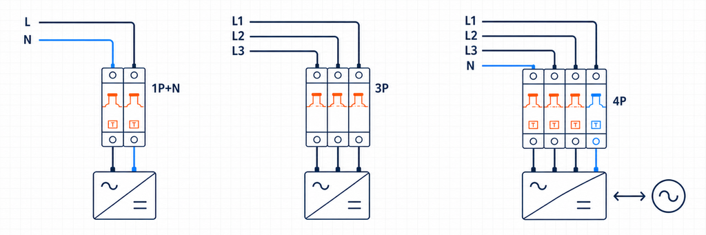
ترتيبات الأقطاب RCBO 1P بالإضافة إلى N، 3P و 4P للدارات المدعومة بالعواكس| الترتيب | النظام المحتمل | التأكيد المطلوب |
|---|---|---|
| 1P+N | خط أحادي الطور ومحايد | فصل المحايد، اتجاه الخط/الحمل وموقع القضيب الناقل |
| 2P | أحادي الطور مع فصل قطبين | أي الأقطاب يتم تبديلها ومحميّة من التيار الزائد |
| 3P | ثلاثي الطور بدون محايد | لا حاجة للتشغيل أو الاستشعار للمحايد |
| 3P+N | ثلاثي الطور مع محايد | سلوك تبديل/حماية المحايد |
| 4P | ثلاثي الطور، أربعة أسلاك مع تشغيل رباعي الأقطاب معلن | تشغيل متزامن وتوافق النظام |
يجب أن يتبع كل موصل مطلوب لترتيب استشعار التيار المتبقي مخطط الشركة المصنعة. المحايد المستعار أو المتجاوز يخلق عدم توازن وقد يجعل الجهاز يفصل حتى عندما تكون الأحمال نفسها سليمة.
الطاقة العكسية تتطلب جهازًا ثنائي الاتجاه معلن
يمكن لمعدات الطاقة الشمسية والبطاريات والمركبات المتصلة بالشبكة أن تغذي الدائرة في الاتجاه المعاكس عن الحمل التقليدي. التبديل اليدوي لا يثبت ملاءمة الاتجاهين. تحقق من اتجاه التغذية المسموح به، اتجاه الأطراف، أداء القصر في كل اتجاه، سلوك النيوترال ونظام اللوحة المعتمد.
RCBO هو جزء واحد فقط من سلسلة الحماية هذه. لا يحل محل العزل المطلوب، وظائف منع الانعزال، الحماية من الارتفاعات المفاجئة أو تحديد المصدر الآمن.
نتيجة دائرة العاكس
400 V AC، 3P/3P+N/4P حسب نظام الموصل الفعلي، نوع التيار المتبقي المطلوب من قبل مصنع المحول، الحساسية المطلوبة حسب قواعد التطبيق، منحنى C/D فقط بعد بدء التشغيل والتحقق من العطل، الاستخدام الثنائي الاتجاه المصرح به حيث يمكن أن يعكس التيار، وسعة القطع فوق مستوى عطل المشروع.
هذه المواصفة أطول لأن النظام يحمل المزيد من الواجهات. اختصارها إلى "4P C32 30 mA" سيتجاهل القرارات التي من المرجح أن تؤثر على التوافق.
مفسر التصنيفات: ما يثبته كل وسم
يمكن الآن تقليل ملفات المشروع الثلاثة إلى جدول فك تشفير واحد. كل تصنيف يغلق مخاطرة مختلفة؛ لا يمكن لقيمة واحدة أن تحل محل أخرى.
| حقل RCBO | المعنى الهندسي | دليل المشروع | الفشل إذا تم تجاهله |
|---|---|---|---|
| الجهد/التردد المقنن | شروط التغذية للتشغيل المصرح به | رسومات النظام وبيانات المعدات | تشغيل غير صحيح أو تصنيف غير صالح |
| In (A) التيار المقنن (أمبير) | التيار المقنن لقسم التيار الزائد | Ib، Iz المصحح وعبء الحمل | فصل الحمل الزائد أو كابل غير محمي |
| منحنى B/C/D | استجابة مغناطيسية فورية | بيانات تيار التدفق والتيار العطل | فصل بدء التشغيل المزعج أو عدم كفاية إزالة العطل |
| النوع AC/A/F/B | قدرة شكل موجة التيار المتبقي | طوبولوجيا الحمل وتعليمات المصنع | الفشل في الاستجابة بشكل صحيح لشكل الموجة المحتمل |
| IΔn (mA) | حساسية التيار المتبقي | هدف الحماية وقاعدة التركيب | مستوى الحماية الخاطئ أو استمرارية ضعيفة |
| الأقطاب/النيوترال | الموصلات التي يتم استشعارها وتبديلها وحمايتها | مخطط الخط الواحد ونظام التأريض | عزل غير صحيح، استشعار أو تشغيل النيوترال |
| سعة الفصل (kA) | أقصى قدرة معلنة على مقاطعة التيار القصير | التيار القصير المتوقع | جهاز مستخدم خارج قدرته المختبرة على المقاطعة |
| واجهة الاتجاه/اللوحة | اتجاه التغذية والتوافق الفيزيائي | بيانات التيار وإعلان اللوحة | تركيب غير صحيح، عدم تطابق قضبان التوصيل أو مشكلة عكس الطاقة |
IEC 61009-1:2024 يحدد متطلبات المنتج والاختبارات الخاصة بـ RCBOs للاستخدامات المنزلية والمماثلة ضمن نطاقه المحدد. لا يحل محل كود التركيب الوطني. مطابقة المنتج تجيب عما إذا كان RCBO يفي بمتطلبات المنتج المعلنة؛ والامتثال للتركيب يجيب عما إذا كان الجهاز مطبقًا بشكل صحيح في الدائرة.
لماذا 10، 30، 100 و300 mA ليست درجات جودة
قيمة IΔn الأقل أكثر حساسية، لكن "أكثر حساسية" لا تعني "أفضل لكل موقع". قد يتم اختيار أجهزة 10 ملي أمبير لمهام محلية أو ذات حساسية أعلى محددة. 30 ملي أمبير يستخدم على نطاق واسع للحماية الإضافية في الدوائر النهائية. قيم 100 و300 ملي أمبير يمكن أن تخدم أدوارًا مختارة في المستويات العليا أو المعدات أو مخاطر الحريق.
جهاز 100 أو 300 ملي أمبير في المستوى الأعلى لا يحل محل حماية 30 ملي أمبير في المستوى الأدنى حيثما تكون 30 ملي أمبير مطلوبة. وعلى العكس، تركيب حماية فورية 30 ملي أمبير في المستويين الأعلى والأدنى يمكن أن يضعف الانتقائية لأن كلا الجهازين يكتشفان نفس خلل الأرض.
عند استخدام حماية التيار المتبقي في المستوى الأعلى، يجب تنسيق كل من العتبة وزمن التشغيل. وظيفة انتقائية/مؤجلة زمنياً يجب أن تكون عند المستوى المسموح به بتصميم التركيب؛ ويجب ألا تؤخر وظيفة الحماية النهائية التي يجب أن تعمل بسرعة.
6 kA أو 10 kA قرار موقعي
يجب أن تكون سعة الفصل على الأقل مساوية للتيار القصير المتوقع عند نقطة تركيب RCBO وفقًا لظروفه المعلنة. يمكن للوحة قريبة من المحول أن تحتوي على مستوى خلل أعلى من دائرة نهائية بعيدة، حتى لو كان المبنى البعيد أكبر في الحجم.
استخدم حسابًا أو قياسًا أو سجل مستوى خلل موثوق للمشروع. إذا تم اقتراح حماية احتياطية في المستوى الأعلى، استخدم تركيبة مختبرة أو معلنة من الشركة المصنعة. قاطع في المستوى الأعلى بسعة مقاطعة كبيرة لا ينقل تلقائيًا تلك السعة إلى RCBO في المستوى الأدنى.
الحماية الاحتياطية والانتقائية مختلفتان أيضًا. قد تقطع مجموعة الأجهزة خللًا عاليًا بأمان بينما يفتح كلا الجهازين. إذا كانت الاستمرارية تتطلب فصل الدائرة الأدنى فقط، احصل على دليل الانتقائية لنطاق التيار المعني.
حوّل بيانات المشروع إلى وصف قابل للطلب
قبل اختيار نموذج، اجمع سجل مشروع قصير واحد:
- البلد/السوق ومتطلبات التركيب المطبقة;
- جهد النظام، التردد وترتيب التأريض;
- موصلات أحادية الطور أو ثلاثية الطور، بما في ذلك النيوترال;
- وصف الحمل، طوبولوجيا المحول الإلكتروني وتيار بدء التشغيل;
- تيار التصميم وسعة الكابل المصححة;
- هدف الحماية من التيار المتبقي المطلوب;
- التيار القصير المتوقع عند اللوحة;
- اتجاه تدفق الطاقة في كل وضع تشغيل;
- نموذج وحدة المستهلك/لوحة التوزيع، قضيب التوصيل وعرض الوحدة المتاح;
- متطلبات الطرف، البيئة، الإشارة والملحقات.
ثم اكتب المواصفة في سطر واحد:
[voltage/frequency], [poles and neutral arrangement], [In], [curve], [Type AC/A/F/B], [IΔn], [breaking capacity], [supply direction], [product standard/market approval], [board and busbar interface].
هذا السطر أكثر فائدة من طلب "RCBO جيد" من المورد. يمنح فرق الهندسة والمشتريات مرجعًا موحدًا ويكشف عن المعلومات المفقودة قبل الالتزام بالعينات أو الإنتاج.
تحقق من صحة RCBO المختار في اللوحة الفعلية
يمكن لمجموعة تصنيف صحيحة تقنيًا أن تفشل عند واجهة التجميع. قبل أن يقبل الموزع نطاق استبدال أو يفرج OEM عن وحدة المستهلك، يجب فحص RCBO المختار في الحاوية المقصودة مع قضيب التوصيل، الموصلات والملحقات المقصودة.
الملاءمة الميكانيكية والتوصيل الكهربائي
تأكيد عرض الوحدة، التثبيت على سكة DIN، موقع أسنان قضيب التوصيل، موقع الحيادي والوصول إلى الطرفية. قد يستخدم جهاز موصوف بأنه 1P+N سلك حيادي طائر، أو طرفية حيادية على جانب معين، أو تباعد مختلف لقضيب التوصيل مقارنة بجهاز 1P+N آخر. الأبعاد الأمامية المتشابهة لا تثبت إمكانية التبادل.
تحقق من مادة الموصل المسموح بها، المقطع العرضي الصلب/المرن ومتطلبات الطرفية. حضّر الموصلات كما هو معلن وطبق عزم الربط المحدد للطرفية. يمكن للاتصال الفضفاض أن يسبب حرارة دون تجاوز تيار حمل الدائرة، في حين أن العزم الزائد قد يتلف الطرفية أو الموصل.
الدليل الوظيفي
يجب أن يميز التشغيل بين نظامي الفصل. حيث يوفر الجهاز مؤشرًا منفصلًا، سجّل ما إذا كانت عملية الاختبار تُبلغ عن تيار متبقي أو تيار زائد. تحقق من وظيفة زر الاختبار تحت ظروف التغذية التي يحددها المصنع، ثم أكمل اختبارات التركيب المطلوبة حسب القواعد المعمول بها. زر الاختبار يفحص مسارًا وظيفيًا داخليًا؛ لا يقيس الحلقة الكاملة لتيار الأرض، حالة العزل أو كل متطلبات زمن الفصل.
بالنسبة للدوائر التي تحتوي على العديد من الأحمال الإلكترونية، سجّل تيار الحمل الطبيعي، ذروة بدء التشغيل والتسرب الثابت بعد التشغيل. هذه القيم الثلاثة تشكل خط الأساس. إذا ظهرت عمليات فصل بعد شهور، يمكن للصيانة مقارنة الأدلة الجديدة مع الحالة الأصلية بدلاً من استبدال الأجهزة بالتجربة والخطأ.
درجة الحرارة والتجميع
يمكن لعدة أجهزة معيارية محملة مركبة جنبًا إلى جنب أن تعمل في بيئة محلية أكثر دفئًا مما تشير إليه درجة حرارة الغرفة. تؤثر تهوية الحاوية، المكونات المجاورة المنتجة للحرارة، حجم الموصل والتحميل المستمر على درجة الحرارة. طبق تعليمات تخفيض التصنيف أو التباعد الخاصة بالمصنع حيثما ينطبق؛ لا تستجب لفصل حراري بزيادة تصنيف الأمبير دون إعادة فحص حماية الكابل.
التحكم في الدفعة والوثائق
بالنسبة لـ OEM أو الموزع، قم بتثبيت المواصفات المعتمدة في قائمة المواد: الطراز الدقيق، المنحنى، نوع التيار المتبقي، IΔn، الأقطاب، قدرة الفصل، ترتيب الطرفيات، الموافقة والملحقات المتوافقة. قد يغير البديل الذي يطابق التيار والعرض فقط نوع شكل الموجة أو سلوك الحيادي بصمت.
احتفظ بورقة البيانات الحالية، وثائق الإعلان/الشهادة المطلوبة للسوق المستهدفة، مخطط التوصيل وتحديد الدفعة مع سجل العينة المعتمدة. هذا يحول الاختيار إلى تحكم إنتاجي قابل للتكرار بدلاً من محادثة هندسية لمرة واحدة.
فصل الامتثال للمنتج عن الامتثال للتركيب
علامة IEC مهمة، لكنها لا تحدد مكان أو كيفية تركيب RCBO. IEC 61009-1:2024 تعرف المعيار على المتطلبات العامة والاختبارات لـ RCBOs للاستخدامات المنزلية والمماثلة ضمن نطاقه المحدد. تحدد قواعد التوصيل الوطنية، اللوائح المحلية، مواصفات المشروع والسلطة المختصة تطبيق التركيب.
| سؤال | من أين يأتي الجواب | مثال |
|---|---|---|
| هل تم تقييم RCBO كمنتج؟ | معيار المنتج، الشهادة ووثائق المصنع | الجهد المعلن، التيار، IΔn، النوع وسعة القصر |
| هل الحماية من التيار المتبقي مطلوبة هنا؟ | قواعد التركيب الوطنية وتصميم المشروع | مقبس، خارجي، موقع رطب أو دائرة معدات خاصة |
| أي نوع من التيار المتبقي مسموح؟ | قواعد التركيب بالإضافة إلى تعليمات المعدات | تقييد على النوع AC أو متطلبات ناتجة عن معدات المحول |
| هل ستفصل الدائرة في الوقت المناسب؟ | حساب/اختبار التركيب وخصائص الجهاز | ظروف حلقة الخطأ لمنحنى B/C/D المختار |
| هل يمكن لـ RCBO أن يناسب هذه اللوحة؟ | إعلانات نظام اللوحة ومصنع الجهاز | قضيب التوصيل، الطرفيات، موقع الحيادي وتصنيف الحاوية |
هذا التمييز مهم في مشاريع التصدير. قد يتطلب تكوين المنتج المقبول في سوق ما نوع تيار متبقي مختلف، ترتيب أقطاب، علامة اعتماد أو نظام لوحة توزيع مختلف في سوق آخر. لا تحول قاعدة وطنية إلى ادعاء IEC عالمي، ولا تفترض أن شهادة مكون توافق اللوحة المكتملة.
فئة دليل اختيار BEAMA RCD مصدر موثوق مفيد لمنطق شكل الموجة والتطبيق، خصوصًا حول الأحمال الإلكترونية الحديثة. لا تزال مراجع التركيب الإقليمية بحاجة إلى التطبيق ضمن اختصاصها. لسوق آخر، استخدم القواعد الوطنية والتعليمات الخاصة بالمعدات ذات الصلة.
مكان تركيب RCBO وأين لا يُستخدم
يجمع RCBO بين الحماية من التيار المتبقي والحماية من الحمل الزائد والدوائر القصيرة. عادةً ما يتطلب تنسيق حماية التيار الزائد، في حين أن RCCB تنسيق حماية التيار الزائد، في حين أن MCB لا يوفر حماية من التيار المتبقي. غالبًا ما تحسن بنية RCBO لكل دائرة استمرارية العطل وعزل الخطأ، ولكن يجب أن يظل منسقًا مع الحماية العليا ولوحة التوزيع.
عادةً لا يتعرف RCBO على توقيعات القوس الكهربائي الخطرة. إذا كان تخفيف عطل القوس جزءًا من المشروع، فاستخدم دليل JUTRION AFDD لتحديد وظائف الحماية المطلوبة. كما أن RCBOs لا تحل محل SPDs أو العوازل أو الحماية الخاصة بالمعدات لمجرد أن عدة وظائف تشترك في غلاف واحد.
اختر وظيفة الحماية قبل رقم الكتالوج
بدأت دائرة المكتب بأحمال إلكترونية غير متوقعة، لذا تحكم نوع A والحماية الفردية 30 mA في القرار. بدأت دوائر الإضاءة والمضخات بسلوك بدء التشغيل، لذا كان اختيار منحنى B/C يعتمد على كل من تيار البدء وتيار العطل. بدأت دائرة العاكس بناءً على شكل الموجة، وطوبولوجيا الموصل، والقدرة العكسية، لذا كانت تعليمات المعدات والموافقة ثنائية الاتجاه مهمة قبل الأمبير.
هذه هي قاعدة الاختيار القابلة للنقل: حدد العطل الذي يجب على RCBO اكتشافه، اثبت مسار الكابل والعطل، ثم أكمل الواجهة الفيزيائية. رقم الكتالوج الصحيح هو ناتج هذه العملية، وليس نقطة البداية.
تقدم JUTRION RCBOs للتوزيع أحادي الطور وثلاثي الطور مع تركيبات متعددة للأقطاب، التيار، الحساسية، نوع شكل الموجة، المنحنى وسعة القطع. شارك سجل المشروع أعلاه عند طلب دعم الاختيار حتى يمكن التحقق من النموذج المقترح مقابل الدائرة الحقيقية.
الأسئلة الشائعة
هل يجب أن أختار RCBO من النوع A أم النوع AC؟
يكشف النوع AC التيار المتبقي المتناوب الجيبي، بينما يكشف النوع A أيضًا التيار المتبقي المستمر النابض. نظرًا لأن العديد من الأجهزة الحديثة تحتوي على مقومات ومزودات طاقة بنمط التبديل، فإن النوع A غالبًا ما يكون نقطة البداية العملية للدوائر العامة للمقابس، الإضاءة والأجهزة. يجب أن يتبع الاختيار النهائي تعليمات المعدات المتصلة وقواعد التركيب المعمول بها.
هل RCBO بقيمة 30 mA هو الخيار الصحيح دائمًا؟
لا. تُستخدم قيمة 30 mA عادةً حيثما يلزم حماية إضافية، لكنها ليست قيمة عالمية لكل دائرة. يجب التحقق من قواعد التطبيق، التسرب الثابت المتوقع، الانتقائية العليا ومتطلبات المعدات. كما أن قيمة 30 mA لا تحدد تصنيف تيار الحمل لـ RCBO.
ما الفرق بين RCBO من النوع B ومنحنى B؟
تصف وظائف مختلفة. يحدد النوع B قدرة الكشف عن التيار المتبقي، بما في ذلك التيار المستمر الناعم ضمن خصائص الجهاز المعلنة. يحدد منحنى B نطاق التشغيل اللحظي لقسم التيار الزائد. لذلك يمكن أن يكون لـ RCBO سلوك تيار متبقي من النوع B وخصائص تيار زائد بمنحنى C.
متى يجب أن أختار RCBO بمنحنى C بدلاً من منحنى B؟
اعتبر منحنى C عندما يكون تيار بدء التشغيل المؤكد من معدات مثل المحركات، المحولات أو مجموعات محركات LED قد يدخل منطقة التشغيل المغناطيسي لمنحنى B. منحنى C ليس علاجًا تلقائيًا للتشغيل الخاطئ: يجب أن توفر الدائرة تيار عطل كافٍ لوقت الفصل المطلوب، ويجب أن تؤكد إشارة الفصل أولاً أن الحدث هو تيار زائد وليس تيار متبقي.
هل أحتاج إلى RCBO 1P+N، 2P، 3P أو 4P؟
اختر ترتيب الأقطاب بناءً على موصلات الإمداد الفعلية وطريقة الفصل المطلوبة. قد تستخدم دائرة خط-ونيوتر أحادي الطور 1P+N أو 2P حسب المنتج وتصميم التركيب. قد تتطلب الدوائر ثلاثية الطور 3P، 3P+N أو 4P حسب وجود النيوتر وكيفية فصله واستشعاره. اتبع دائمًا مخطط الأسلاك الخاص بالشركة المصنعة.
هل يمكنني استخدام RCBO من النوع A القياسي مع العاكس؟
فقط عندما يسمح بذلك مصنع العاكس وقواعد التركيب المعمول بها. قد تتطلب معدات الإلكترونيات القوية النوع A، النوع F، النوع B أو ترتيبًا منسقًا مع مراقبة التيار المستمر المتبقي المدمجة. تحقق أيضًا من تكوين الأقطاب، معالجة النيوتر، اتجاه الإمداد المسموح به والتشغيل ثنائي الاتجاه المعلن حيث يمكن أن يتدفق التيار عائدًا نحو الشبكة.
المراجع الفنية
