

Cómo dimensionar un ATS para inversores solares híbridos: explicación del conmutador de respaldo conectado a la red frente al desconectado.
Para dimensionar un ATS para un inversor solar híbrido, primero identifique qué transferirá realmente el interruptor. No lo seleccione solo por los kilovatios del arreglo fotovoltaico. En el punto instalado, compare la corriente máxima de paso por la red, la corriente máxima de salida de respaldo del inversor y la corriente de diseño del cuadro de carga transferida. Use la corriente más alta que pueda pasar legítimamente por el ATS, luego verifique la disposición de polos, la capacidad de cortocircuito, la categoría de utilización, la lógica de transferencia y la compatibilidad con la arquitectura de respaldo aprobada del inversor.
Esta distinción es importante porque “conectado a red”, “híbrido” y “aislado” describen comportamientos eléctricos diferentes. Un inversor fotovoltaico convencional conectado a red normalmente deja de suministrar energía durante un corte prolongado de la red. Un inversor híbrido puede contener un relé de transferencia interno y una salida de respaldo dedicada. Un inversor aislado puede formar su propio bus CA y usar la red o un generador solo como entrada alternativa. Instalar el mismo ATS genérico en los tres sistemas puede producir disparos intempestivos, cargas de respaldo sin energía, comandos de transferencia conflictivos o un camino paralelo inseguro.
Esta guía explica cómo establecer el límite correcto del ATS, calcular la corriente y especificar la disposición de conmutación para cada arquitectura. Complementa nuestra guía general de dimensionamiento de interruptores de transferencia automática, mientras se enfoca específicamente en sistemas solares híbridos y de respaldo con batería.
Respuesta rápida: ¿Qué clasificación debe controlar el tamaño del ATS?
La corriente de control depende de la ubicación del ATS:
| Ubicación del ATS | Fuentes que se seleccionan | Base de corriente | Error común |
|---|---|---|---|
| Antes de la entrada CA del inversor | Red y generador | Corriente máxima permitida de entrada o paso CA, demanda de carga transferida y límite de fuente | Dimensionar solo a partir de los kW de salida del inversor |
| Después de la salida de respaldo | Salida de respaldo del inversor y derivación de red | Mayor corriente creíble entregada al panel de carga de respaldo | Uso de kW del arreglo fotovoltaico en lugar de corriente del cuadro de respaldo |
| Límite de servicio de todo el edificio | Servicio de la empresa de energía y fuente de isla intencional | Cálculo de servicio/carga más clasificación aprobada de la interfaz de respaldo | Agregar un ATS genérico a un sistema que requiere una interfaz de respaldo listada |
| Bus CA aislado | Inversor y derivación de generador o empresa de energía | Corriente máxima de carga transferida y límites continuos de ambas fuentes | Permitir que dos controladores independientes conecten fuentes sin enclavamiento coordinado |
El tamaño de marco seleccionado no debe ser inferior a la corriente de diseño máxima a través del interruptor. Sin embargo, los amperios por sí solos no completan la especificación. El ATS final también debe adaptarse a la tensión del sistema, el número de fases, la disposición de neutro y puesta a tierra, el nivel de falla esperado, el método de transferencia y las reglas de instalación aplicables.
Comience con la arquitectura, no con el catálogo de ATS
Antes de calcular la corriente, trace una línea desde cada fuente posible hasta las cargas. Marque el punto de conexión de la empresa de energía, la entrada de red del inversor, la salida de respaldo del inversor, la batería, el generador, el panel de cargas esenciales y cada dispositivo capaz de abrir o cerrar una ruta de fuente. Si el mecanismo de conmutación, el controlador, la detección de fuente y el enclavamiento aún no le resultan familiares, revise cómo funciona un interruptor de transferencia automática y cómo seleccionar uno antes de finalizar el diagrama unifilar. El dibujo debe hacer imposible que la empresa de energía y una fuente de isla no sincronizada se conecten juntas.
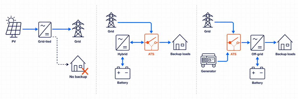
El Departamento de Energía de EE. UU. distingue los inversores que siguen la red, que requieren una red en funcionamiento, de los inversores que forman red, que pueden operar cuando la red no está disponible. También señala que los inversores ordinarios conectados a la red se desconectan durante perturbaciones de red mayores o sostenidas. Por eso un ATS no puede convertir un inversor estándar conectado a la red en una fuente de respaldo. El respaldo intencional requiere un inversor y una disposición de aislamiento diseñados específicamente para operación en isla.
Arquitectura 1: Fotovoltaica convencional conectada a red sin respaldo
Un inversor fotovoltaico convencional conectado a red opera en paralelo con la red eléctrica y exporta o compensa energía mientras la red está activa. Durante un corte, la protección anti-isla desconecta el inversor. No existe una fuente CA alternativa estable para que un ATS seleccione.
En esta arquitectura, instalar un ATS entre la red y la vivienda no hace que el sistema fotovoltaico continúe operando. El inversor aún necesita una referencia válida de red y no está autorizado a energizar un circuito aislado a menos que esté diseñado y aprobado para formar esa isla. Si se requiere respaldo ante cortes, la arquitectura del sistema debe cambiar: típicamente añadiendo una batería compatible, función de inversor formador de red, interfaz de respaldo y límite de carga esencial.
Arquitectura 2: Inversor híbrido con un dispositivo de transferencia interno
Muchos inversores híbridos tienen terminales separados de red y de respaldo. Internamente, un dispositivo de transferencia aísla la empresa de energía y suministra una salida de respaldo designada desde la batería y el inversor durante un corte. En este caso, la documentación del inversor —no un diagrama genérico— define la disposición de neutro permitida, los dispositivos de protección, el tamaño del panel de respaldo, la secuencia de reconexión y si se permite un ATS externo.
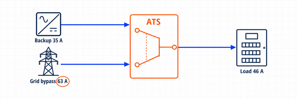
Un ATS adicional aún puede cumplir un propósito legítimo. Por ejemplo, puede derivar un inversor fallido y reconectar el panel de cargas esenciales directamente a la empresa de energía. En esa disposición, el ATS no está creando la isla solar. Está seleccionando entre la salida de respaldo del inversor y una derivación de red. Por lo tanto, la clasificación de corriente del ATS debe cubrir la corriente máxima disponible en cualquiera de esas rutas.
Algunas plataformas híbridas en su lugar usan un controlador de sistema dedicado o una interfaz de respaldo que ya contiene la función de transferencia. Reemplazar o duplicar esa función con un ATS de propósito general puede anular el monitoreo del sistema, el control de neutro, la lógica contra isla o la certificación del fabricante. Trate “interruptor de transferencia interno”, “interfaz de respaldo” y “ATS de derivación externo” como tres componentes diferentes hasta que el diagrama unifilar aprobado demuestre lo contrario.
Arquitectura 3: Inversor aislado o formador de red con entrada CA alternativa
Un inversor aislado normalmente establece tensión y frecuencia para el bus CA local. La red eléctrica o un generador puede conectarse a una entrada CA para que el inversor/cargador transfiera cargas, cargue la batería o apoye la alimentación. Muchos inversores/cargadores ya contienen un relé de transferencia interno. Si el diseño usa un ATS externo, puede seleccionar entre utilidad y generador en la entrada del inversor, o entre salida del inversor y fuente de bypass en el cuadro de cargas.
Esas dos posiciones no son intercambiables. Un ATS del lado de la entrada ve la corriente aceptada y transmitida por el inversor/cargador. Un ATS de derivación del lado de la salida ve la corriente demandada por las cargas transferidas. El controlador del lado de la entrada también puede necesitar contactos de arranque/parada del generador, tiempo de calentamiento, ventanas de aceptación de voltaje y frecuencia, y una secuencia de enfriamiento. El dispositivo del lado de la salida debe evitar la realimentación de la salida del inversor cuando la derivación está activa, a menos que el diseño del fabricante lo permita expresamente.
Los cuatro valores de corriente que debe registrar
Una hoja de selección confiable registra cuatro valores de corriente en lugar de un solo número de potencia solar.
Corriente de diseño de la carga transferida
Esta es la corriente requerida por las cargas conectadas aguas abajo del ATS. No es automáticamente la clasificación del servicio principal ni automáticamente la clasificación del inversor. Un interruptor de transferencia para todo el edificio puede transportar la demanda calculada del edificio. Un ATS de carga esencial puede transportar solo refrigeración, iluminación, controles, comunicaciones, receptáculos seleccionados y otros circuitos priorizados.
Utilice el cálculo de carga del proyecto y el código eléctrico aplicable. Tenga en cuenta cargas continuas, motores, transformadores, compresores y operación simultánea. Si la reducción de carga es parte del diseño, documente qué cargas se desconectan antes de usar la cifra reducida.
Corriente máxima de salida de respaldo del inversor
Lea la hoja de datos o manual de instalación del inversor. Prefiera su corriente máxima continua de salida de respaldo declarada sobre un cálculo basado en la potencia nominal de marketing. Si solo está disponible la potencia aparente, los cálculos básicos de CA son:
Monofásico: I = S ÷ V
Trifásico: I = S ÷ (√3 × V)
Para una salida monofásica de 10 kVA y 230 V, la corriente ideal es aproximadamente 43.5 A. Para una salida trifásica de 30 kVA y 400 V, es aproximadamente 43.3 A por fase. Estos valores son puntos de partida, no permiso para ignorar el límite de corriente del fabricante, la curva de sobrecarga, el límite de desbalance de fase o la reducción por temperatura ambiente.
Corriente de paso a través de la red o corriente de bypass
Este es frecuentemente el valor controlador. Un inversor híbrido con una salida de respaldo de 8 kW puede permitir que una corriente de red mayor pase a través de su relé interno mientras la utilidad está disponible. Asimismo, un camino de bypass externo puede alimentar directamente el panel de carga esencial desde la red.
Si 63 A pueden pasar por el ATS en modo red, seleccionar un ATS de 40 A porque el inversor produce solo 8 kW es incorrecto. Los contactos y terminales del interruptor aún soportan el camino de 63 A. Registre la corriente máxima de entrada/paso CA del inversor, la clasificación del interruptor de bypass y el cálculo de carga aguas abajo, luego use el diseño coordinado más restrictivo.
Corriente máxima permitida por cada fuente y dispositivo de protección
El alimentador de la utilidad, el interruptor del generador, la protección de salida del inversor, los conductores y el dispositivo principal del cuadro de distribución establecen límites. El ATS no crea capacidad de fuente adicional, y su clasificación de corriente no protege los cables por sí misma. Un interruptor de transferencia de clase PC comúnmente depende de la protección contra sobrecorriente coordinada aguas arriba; un arreglo de clase CB integra funciones de interruptor automático. Seleccione y verifique toda la cadena de protección.
Un método práctico de dimensionamiento del ATS para inversores híbridos
- Confirme que el inversor puede formar una isla. Si es solo de PV y sigue la red, deténgase: no hay una fuente de respaldo válida para el ATS.
- Utilice la arquitectura aprobada por el fabricante. Identifique la interfaz de respaldo requerida, el relé de transferencia interno, el interruptor externo compatible o el arreglo de bypass permitido.
- Marque la posición del ATS. Indique exactamente qué dos fuentes se conectan a la Fuente I y la Fuente II, y qué panel se conecta a la salida común.
- Defina las cargas transferidas. Utilice un cronograma de carga esencial o el cálculo de demanda de todo el edificio en lugar de agregar placas de nombre de electrodomésticos indiscriminadamente.
- Registre la corriente de salida de respaldo. Utilice la corriente máxima declarada y anote la capacidad de sobrecarga de corta duración por separado.
- Registre la corriente de paso a través de la red o corriente de bypass. Verifique el límite de entrada del inversor, la clasificación del relé interno, el alimentador de bypass y el dispositivo principal del panel.
- Seleccione la corriente continua. El ATS debe soportar la corriente máxima creíble en su posición instalada, sujeta a las reglas del código, reducción, temperatura del recinto e instrucciones del fabricante.
- Complete las verificaciones no amperimétricas. Verifique el voltaje, la frecuencia, las fases, los polos, el tratamiento del neutro, la clasificación de cortocircuito, la categoría de utilización, el tiempo de transferencia, la detección, el voltaje de control y el enclavamiento.
- Valide cada estado operativo. Revise la operación normal de la red, la falla de la red, la falla del inversor, la batería agotada, la operación del generador, el bypass de mantenimiento y el retorno de la red.
Ejemplo práctico: Inversor híbrido de 8 kW con un bypass de red
Considere un sistema ilustrativo de 230 V monofásico con estos valores de diseño:
- Clasificación de respaldo del inversor híbrido: 8 kVA continuo
- Corriente máxima de salida de respaldo declarada: 35 A
- Corriente de paso permitida de la red: 63 A
- Corriente de diseño del panel de carga esencial: 46 A cuando la red está disponible
- Límite de gestión de carga en modo de respaldo: 32 A
- Posición del ATS externo: salida de respaldo del inversor frente al bypass directo de la red
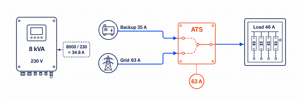
La corriente aproximada del inversor a partir de la potencia aparente es 8,000 ÷ 230 = 34.8 A, consistente con la salida declarada de 35 A. Pero un ATS de 40 A no es automáticamente adecuado. En modo de bypass de red, el panel de carga esencial puede consumir 46 A y el camino de origen está permitido hasta 63 A.
En esta ubicación, la selección de corriente del ATS está controlada por el bypass de red y el camino de carga transferida, no por la salida del inversor de 8 kVA. Una clase de 63 A puede ser la clase de corriente práctica mínima si todas las verificaciones de carga continua, temperatura, envolvente, terminal y código local aplicables lo permiten. Se puede seleccionar un marco de 80 A donde el diseño coordinado, la reducción ambiental, la terminación del conductor o el estándar del proyecto requieran más margen. La respuesta final no se puede obtener solo de 8 kW.
El controlador de gestión de carga debe mantener la demanda en modo de respaldo dentro de la capacidad de 35 A del inversor. Sobredimensionar el ATS a 63 A o 80 A no hace que el inversor sea capaz de suministrar 46 A durante un corte. Esa es una restricción separada de gestión de energía y potencia.
¿Transferencia de toda la casa o transferencia de carga esencial?
Esta elección cambia tanto el tamaño del ATS como el comportamiento del sistema. Un arreglo de transferencia de toda la casa coloca el límite de respaldo alrededor de la mayor parte o de toda la distribución del edificio. Por lo tanto, el ATS y la interfaz asociada pueden necesitar coincidir con el servicio o la demanda calculada, incluso cuando el inversor solo puede suministrar una fracción de esa corriente. El respaldo exitoso de toda la casa generalmente depende de la gestión automática de carga que desconecta la calefacción de agua, la gran refrigeración, la carga de vehículos eléctricos, la cocción eléctrica u otras cargas antes de que el inversor se sobrecargue.
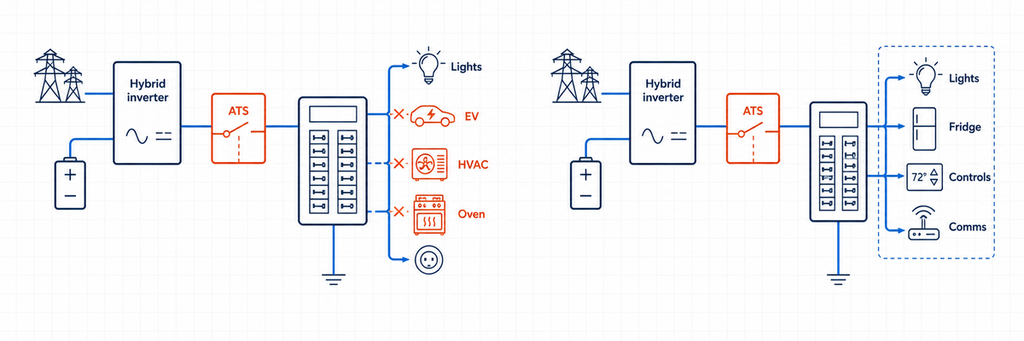
Un arreglo de carga esencial crea un panel de menor tamaño en la parte posterior. Solo los circuitos seleccionados se transfieren a la energía del inversor. Esto a menudo permite una clasificación de corriente ATS más baja, conductores más pequeños y una autonomía de batería más predecible. También hace visible el límite de corriente en modo de respaldo: si el panel contiene 32 A de demanda gestionada, el diseñador puede verificar eso contra la salida declarada del inversor en lugar de esperar que los ocupantes eviten cargas simultáneas.
Utilice la siguiente decisión:
- Elija un panel de carga esencial cuando la salida del inversor sea materialmente inferior a la capacidad del servicio, la energía de la batería sea limitada o la priorización confiable de la carga sea más importante que la conveniencia.
- Considere la transferencia de toda la casa cuando el controlador del sistema aprobado lo soporte, el inversor y la batería pueden mantener la demanda prevista, y la reducción automática de carga está documentada.
- No reduzca la corriente del ATS simplemente porque el software en modo de respaldo limita el inversor. Si los mismos contactos llevan la demanda total en modo de red, dimensione los mismos para ese camino de red.
Para la adquisición, indique ambos números: “corriente continua del ATS en el límite instalado” y “carga máxima permitida en modo de respaldo.” Responden a diferentes preguntas y evitan que los instaladores traten un interruptor sobredimensionado como evidencia de una capacidad adecuada del inversor.
Los Inversores Híbridos Trifásicos Necesitan Comprobaciones Adicionales
Un cálculo de corriente trifásica asume una potencia aparente equilibrada. Los paneles de respaldo reales pueden estar desbalanceados, y algunos inversores híbridos imponen una corriente máxima por fase o un desbalance de fase máximo permitido. Por ejemplo, un inversor trifásico nominal de 30 kVA, 400 V corresponde aproximadamente a 43.3 A por fase:
I = 30,000 ÷ (1.732 × 400) = 43.3 A por fase
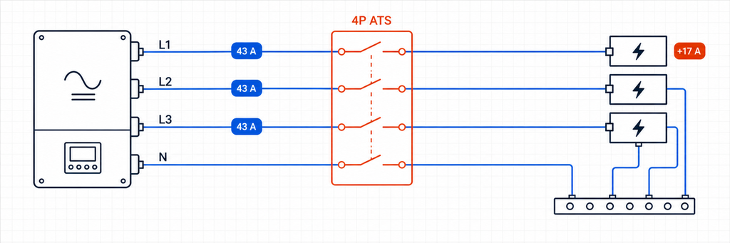
Ese resultado no prueba que un ATS de 50 A sea adecuado. Verifique si la clasificación de paso de red es de 63 A, 80 A u otro valor; si el panel de respaldo puede concentrar cargas monofásicas en una fase; y si el inversor puede energizar las tres fases durante la operación en isla. Una carga de 4 kW añadida a una fase representa aproximadamente 17.4 A a 230 V aunque el total de kVA trifásico aún parezca aceptable.
Elabore un cronograma de fases para las cargas esenciales. Mantenga las grandes cargas monofásicas distribuidas cuando sea posible, y verifique la peor fase en lugar de solo el promedio. Si el inversor permite 40 A en cada fase pero el bypass de red permite 63 A, el ATS en un límite de salida de respaldo/bypass de red puede requerir aún una clase de corriente de 63 A. Los controles de carga en modo de respaldo deben entonces evitar que cualquier fase supere el límite del inversor.
También confirme qué sucede cuando falla una fase. Algunos controladores de ATS transfieren en caso de pérdida de fase; algunos inversores híbridos desconectan la salida completa; y algunas aplicaciones requieren un retraso específico para evitar la operación con energía inestable de la red. El monitoreo de secuencia de fase puede ser necesario para motores y equipos rotativos. La especificación del controlador debe indicar el comportamiento de bajo voltaje, sobrevoltaje, pérdida de fase, secuencia de fase y frecuencia—no simplemente “automático.”
Agregar un Generador a un Sistema Solar Híbrido
Un generador crea una tercera fuente aunque un ATS convencional normalmente selecciona solo dos. Por lo tanto, el diseño necesita una jerarquía clara. Las arquitecturas comunes incluyen:
- Utilidad versus generador en la entrada AC del inversor. El inversor/cargador recibe cualquier fuente AC externa que seleccione el ATS de entrada, mientras que su relé interno gestiona el paso y la operación de la batería.
- Utilidad en la entrada de red del inversor y generador en una entrada dedicada para generador. El controlador híbrido gestiona ambas fuentes sin un ATS de selección de fuente adicional, siempre que el modelo soporte este arreglo.
- Salida de respaldo del inversor frente a bypass del generador en el panel de carga esencial. Esto puede preservar las cargas si el inversor o la batería se vuelven no disponibles, pero la rama del generador y la salida del inversor nunca deben estar paraleladas involuntariamente.
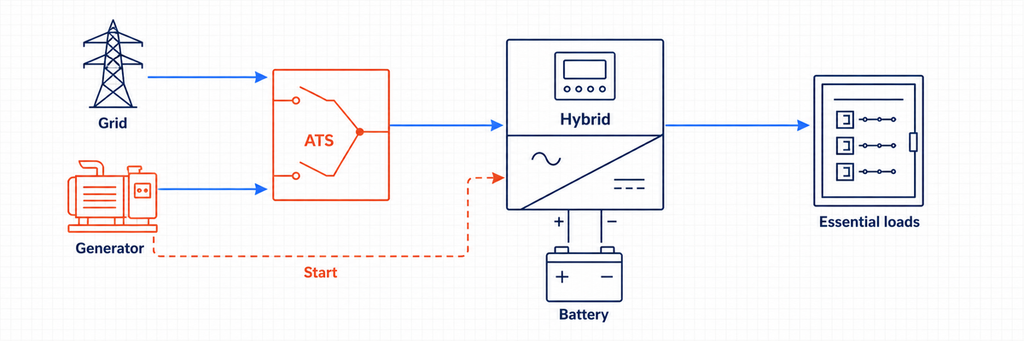
Para un ATS de generador/utilidad en el lado de entrada, calcula la corriente del generador a partir de su clasificación en kVA y compárala con la corriente máxima de entrada AC aceptada por el inversor. Supón que un generador monofásico de 15 kVA y 230 V suministra a un cargador de inversor. Su corriente nominal es de aproximadamente 65.2 A. Si el inversor acepta solo 50 A, sus configuraciones o la protección aguas arriba pueden limitar la corriente de carga y pasaje, pero el circuito de fuente del ATS aún debe coordinarse con el interruptor del generador, los conductores y la ruta de carga real. No asumas que el límite de entrada del software es un sustituto de la protección del circuito.
La operación del generador añade requisitos de control que los diagramas solo de solar no muestran: señal de inicio, intentos de arranque, retraso de calentamiento, verificación de disponibilidad de fuente, tiempo mínimo de funcionamiento, enfriamiento, programación de ejercicio, retroalimentación de bajo combustible o fallo, y umbrales de estado de carga de la batería. Un ATS básico de detección de voltaje puede transferir cargas, pero puede no coordinar la potencia de carga o prevenir que el cargador de inversor sobrecargue un generador pequeño. Donde el inversor híbrido gestiona el generador, utiliza los contactos secos especificados y la secuencia de control. Si el generador arranca pero la carga no se transfiere, sigue la secuencia de diagnóstico de transferencia de generador ATS para localizar el primer controlador o estado de ruta de energía faltante.
Los sistemas de tres fuentes pueden requerir dos etapas de transferencia interbloqueadas o equipos de conmutación de múltiples fuentes diseñados para tal fin. La IEC 60947-6-1:2026 señala límites alrededor de TSE de múltiples fuentes e híbridos dentro de su descripción de alcance, por lo que el ensamblaje completo y la disposición del controlador deben ser verificados en lugar de ensamblados a partir de interruptores no relacionados y asumidos como conformes.
Conectado a la red frente a Fuera de la red: ¿Qué cambia en la secuencia de transferencia?
Secuencia de respaldo híbrido conectado a la red
En operación normal, la utilidad establece la referencia de la red y puede suministrar cargas a través de la ruta de pasaje del inversor. Cuando el voltaje o la frecuencia de la red sale de la ventana permitida, el dispositivo de aislamiento aprobado abre la conexión de la utilidad. Solo después de que se confirme el aislamiento, el inversor formador de red puede energizar el bus de respaldo. Cuando la utilidad regresa y permanece estable durante el retraso configurado, el sistema se resincroniza o realiza una transición abierta de acuerdo con su lógica de control aprobada.
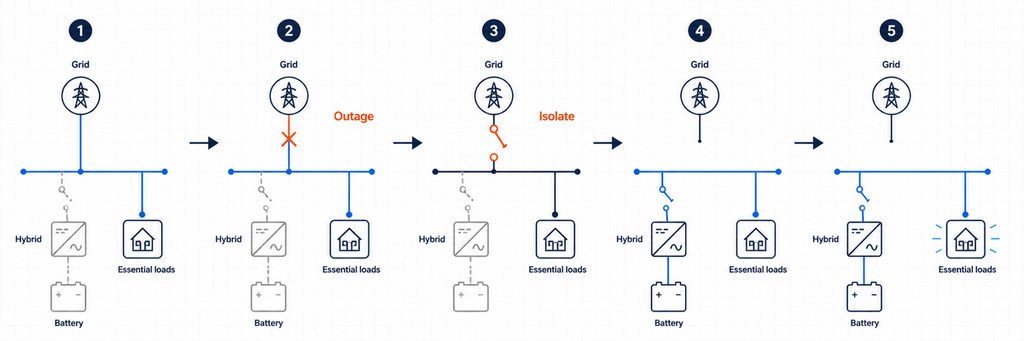
Un ATS genérico que simplemente detecta “sin voltaje” puede no saber si el inversor ha completado la desconexión, si su bus de respaldo es estable o si se permite la reconexión. Por eso, los sistemas híbridos a menudo dependen de un controlador integrado, una interfaz de respaldo dedicada o coordinación de contacto seco especificada por el fabricante del inversor.
Secuencia de Selección de Fuente Fuera de la Red
En una instalación fuera de la red, el inversor es normalmente la fuente que forma la red. La entrada alternativa de la utilidad o generador se vuelve aceptable solo después de que su voltaje y frecuencia se estabilizan. Un ATS del lado de entrada puede elegir entre la utilidad y el generador antes de alimentar el inversor/cargador. El relé interno del inversor luego decide si pasar la fuente aceptada o continuar soportando las cargas con energía de la batería.
Si un segundo ATS del lado de salida proporciona un bypass de mantenimiento, su lógica debe estar coordinada con el inversor. El diseño debe prevenir que una fuente de bypass se conecte a una salida de inversor energizada a menos que el equipo esté específicamente destinado para operación paralela sincronizada. El enclavamiento mecánico y eléctrico no debe depender solo de comandos de software.
Polos, Conmutación de Neutro y Puesta a Tierra
No elija 2P, 3P o 4P únicamente a partir de una simple regla de “fase única frente a tres fases”. Determine si el neutro debe permanecer sólidamente conectado o ser conmutado, cómo se conecta a tierra cada fuente, dónde existe el enlace neutro-tierra y cómo se comporta la protección contra corriente residual en cada estado de la fuente.
Un sistema de línea y neutro monofásico puede utilizar un arreglo de transferencia de dos polos donde ambos conductores deben ser conmutados. Un sistema trifásico de cuatro hilos puede requerir un ATS de cuatro polos cuando la fuente alternativa crea un neutro derivado por separado o referenciado de manera diferente. Otros sistemas mantienen deliberadamente un neutro común. El arreglo correcto depende del diseño del inversor, el código local, los requisitos de la utilidad y el diagrama aprobado por el fabricante.
Un manejo incorrecto del neutro puede crear caminos paralelos de neutro, corriente circulante, protección ineficaz contra corriente residual, disparos innecesarios o un sistema de respaldo flotante. Haga una tabla de estado de neutro y tierra para el modo de utilidad, modo isla, modo generador y bypass de mantenimiento. Si la tabla no muestra una estrategia de unión intencional en cada estado, el diseño no está listo para la instalación.
La Capacidad de Cortocircuito No Es lo Mismo que la Corriente Continua
Los sistemas híbridos tienen dos fuentes de corriente de falla muy diferentes. La utilidad puede entregar una alta corriente de cortocircuito prospectiva. Un inversor normalmente limita la salida electrónicamente y puede suministrar solo un múltiplo modesto de la corriente nominal por un corto período. El ATS aún debe soportar y, donde sea necesario, cerrar sobre el peor deber de falla disponible en su punto de instalación.
Verifique la corriente de falla disponible de cada fuente conectada, el dispositivo de protección aguas arriba y los datos condicionales de cortocircuito o de resistencia y cierre del fabricante del ATS. No asuma que la corriente de falla limitada de un inversor hace que un pequeño interruptor de transferencia sea aceptable si los mismos contactos están conectados a un fuerte bypass de la red.
Para proyectos orientados a la IEC, IEC 60947-6-1:2026 cubre el equipo de conmutación de transferencia utilizado para transferir una carga entre fuentes. Para proyectos en América del Norte, la visión general de certificación de interruptores de UL identifica las categorías UL 1008 para interruptores de transferencia automáticos y no automáticos. Siempre aplique la edición y las reglas de instalación adoptadas por la autoridad competente del proyecto.
Tiempo de Transferencia: Un ATS No Es Automáticamente un UPS
Una transferencia de ATS incluye detección, validación, operación mecánica y tiempo de estabilización. Incluso un interruptor rápido puede crear una interrupción lo suficientemente larga como para reiniciar controles, contactores, equipos de comunicación o computadoras. Un inversor híbrido con un relé de transferencia interno puede soportar una transición más corta que un ATS electromecánico separado, pero el valor real debe provenir de la documentación y las pruebas del sistema.
Clasifique las cargas según la tolerancia a la continuidad. La iluminación y la refrigeración pueden tolerar una breve interrupción. Los servidores, PLC, equipos médicos y dispositivos de red pueden requerir un UPS o un camino de inversor sin interrupciones. No prometa “energía ininterrumpida” según la clasificación de corriente del ATS.
Detalles de Control y Detección que Determinan si Funciona
- Detección de fuente: Mida la tensión y frecuencia en los terminales reales de la fuente. La producción fotovoltaica o el estado de carga de la batería no son equivalentes a una fuente de respaldo CA saludable.
- Retrasos de transferencia: Prevenga el ciclo rápido durante condiciones inestables de la red y permita que un generador o bus de inversor se estabilice.
- Fuente preferida: Decida si la salida de respaldo del inversor, el bypass de la red o el generador es la fuente normal para cada ATS.
- Contactos secos: Confirme las clasificaciones de contacto sin tensión, la polaridad lógica y el comportamiento a prueba de fallos antes de conectar los controles del inversor o generador.
- Lógica de retorno: Defina si el sistema regresa automáticamente a la red, espera la recuperación de la batería o requiere aprobación manual.
- Modo de falla: Decida qué sucede si el controlador del inversor, el motor del ATS, el fusible de detección o el enlace de comunicaciones falla.
Para proyectos que necesitan estado remoto, seleccione un interruptor de transferencia automática con los contactos auxiliares o opciones de comunicación requeridas. Mantenga el interbloqueo de fuente cableada independiente de la supervisión.
Cómo leer las hojas de datos del inversor y del ATS juntas
El manual del inversor y la hoja de datos del ATS utilizan términos diferentes, así que cree un cruce en lugar de comparar una línea de “corriente nominal”.
| Datos del inversor | Datos del ATS para comparar | Pregunta de diseño |
|---|---|---|
| Corriente de respaldo continua máxima | Corriente nominal y categoría de utilización | ¿Pueden los contactos llevar la salida del inversor de forma continua? |
| Corriente máxima de entrada/paso CA | Corriente nominal y capacidad del terminal | ¿Puede el ATS llevar el camino de la red o del generador más grande? |
| Curva de sobrecarga de salida | Deber de hacer/romper y categoría de carga | ¿Causarán eventos de motor o transformador estrés de transferencia o apagado del inversor? |
| Ventanas de tensión/frecuencia de la red y de respaldo | Rango de detección del controlador y umbrales ajustables | ¿Ambos dispositivos estarán de acuerdo en que una fuente es aceptable? |
| Tiempo de transferencia interno | Tiempo de operación y tiempo de retraso intencional del ATS | ¿Qué interrupción experimentará realmente la carga? |
| Diagrama de neutro/puesta a tierra | Disposición de conmutación 2P, 3P o 4P | ¿Cada estado operativo preserva el sistema de unión aprobado? |
| Contribución máxima a fallos | Clasificación de resistencia a cortocircuitos/condicional | ¿Está el interruptor coordinado para fuentes tanto de inversor como de red? |
| Interfaz de contacto seco o de comunicaciones | Entradas, salidas y contactos auxiliares del controlador | ¿Pueden los dispositivos intercambiar estado de permiso, fallo y posición de forma segura? |
Si falta un valor, solicítelo antes de emitir la especificación del interruptor. “Compatible con solar” no es una clasificación eléctrica. Asimismo, “ATS de 63 A” no indica si el dispositivo es adecuado para la tensión, categoría de carga, nivel de fallo, secuencia de conmutación o certificación de mercado.
Errores comunes de dimensionamiento de ATS de inversor híbrido
Dimensionamiento a partir de kW de la matriz PV
Un arreglo de 12 kWp no significa que el ATS soporte 12 kW. La clasificación CA del inversor, el límite de descarga de la batería, el camino de paso por la red y la demanda de carga transferida determinan la corriente en diferentes ubicaciones.
Usando solo la clasificación de salida del inversor
La red o el generador pueden pasar más corriente a través de un ATS de la que el inversor puede producir. Esta es la razón más importante para registrar las calificaciones de paso y de bypass por separado.
Duplicando una Función de Transferencia Interna
Dos controladores automáticos pueden emitir comandos contradictorios, crear interrupciones innecesarias o eludir la secuencia de aislamiento aprobada del inversor. Utilice una relación de control maestro documentada.
Suponiendo que cualquier inversor conectado a la red puede proporcionar respaldo
El Departamento de Energía de EE. UU. explica que los inversores que siguen la red se apagan cuando la energía de la red no está disponible, mientras que se requiere capacidad de formación de red para operación fuera de la red o de respaldo. Un ATS por sí solo no proporciona esa capacidad.
Ignorando el comportamiento del neutro
Una clasificación de corriente puede ser correcta mientras el sistema siga siendo inseguro debido a un arreglo incorrecto de neutro o conexión a tierra. Revise la operación del conductor de protección y la corriente residual en cada estado de transferencia.
Tratando el ATS como protección contra sobrecorriente
Un interruptor de transferencia cambia las rutas de origen. A menos que el producto seleccionado sea específicamente un arreglo de protección de clase CB, aún se requieren interruptores o fusibles coordinados.
Pruebas de puesta en marcha antes de que el sistema entre en funcionamiento
- Verifique la identidad del conductor, el par de apriete de los terminales, la secuencia de fases, la polaridad, la continuidad del neutro y las conexiones de puesta a tierra protectora.
- Confirme que los nombres de las fuentes del ATS coincidan con las fuentes preferidas y alternativas reales.
- Mida la tensión y la frecuencia de la red, el respaldo del inversor y el generador en los puntos de detección.
- Simule una falla de red y confirme que la aislamiento de la utilidad ocurra antes de que el bus de isla se energice.
- Aplique cargas esenciales representativas y verifique que la corriente de respaldo permanezca dentro del límite del inversor.
- Desactive o falle el inversor y verifique la respuesta de bypass prevista sin retroalimentar su salida.
- Restaure la utilidad y confirme el retraso de retransferencia, las verificaciones de estabilidad de la fuente y el estado operativo final.
- Pruebe los estados de batería baja, sobrecarga, parada de emergencia, operación manual y pérdida de comunicación.
- Registre los tiempos de transferencia, corrientes, alarmas, configuraciones del controlador y cambios en el cableado tal como se construyó.
La puesta en marcha debe ser realizada por personal calificado utilizando un procedimiento de prueba aprobado. Los sistemas solares y de baterías conectados a la red pueden energizar conductores desde múltiples direcciones incluso cuando un desconector está abierto.
Lista de verificación de especificaciones del ATS para un proyecto solar híbrido
| Elemento de especificación | Entrada del proyecto |
|---|---|
| Función y ubicación del ATS | Selector de fuente de entrada, bypass de salida de respaldo o aislamiento de servicio |
| Fuente I / Fuente II | Utilidad, generador, salida de respaldo del inversor o combinación aprobada |
| Corriente de diseño de carga transferida | Del programa de carga y las normas locales |
| Corriente de respaldo del inversor | Valor máximo continuo del fabricante |
| Corriente de paso/bypass de la red | Máximo permitido en el punto instalado |
| Corriente de operación nominal | Seleccionado después de la carga, desclasificación y verificaciones de coordinación |
| Voltaje, frecuencia, fases | Coincidir ambas fuentes y la carga |
| Polos y neutro | Basado en el diseño de puesta a tierra aprobado |
| Datos de duty de falla | Corriente de falla disponible y dispositivo de protección coordinado |
| Método de transferencia | Transición abierta a menos que se requiera un método sincronizado aprobado |
| Control y retroalimentación | Umbrales de detección, retrasos, contactos secos, estado, comunicaciones |
| Evidencia de compatibilidad | Diagrama unifilar aprobado por el inversor y certificación aplicable |
Regla de selección final
El tamaño correcto del ATS para un inversor solar híbrido es la clasificación requerida en el límite eléctrico real del interruptor, no el número impreso junto al arreglo fotovoltaico. Primero demuestre que el sistema tiene un método aprobado de formación de red y aislamiento. Luego compare la corriente de carga transferida, la corriente de salida de respaldo del inversor y la corriente de paso o bypass de la red. Seleccione la corriente creíble más alta en esa ubicación y finalice el diseño con verificaciones de polos, neutro, capacidad de fallo, tiempo de transferencia, protección y controlador.
Para una selección específica del proyecto, envíe a JUTRION el diagrama unifilar, voltaje del sistema y fases, modelo de inversor, corriente de salida de respaldo, calificación de paso, cronograma de carga transferida, corriente de falla disponible y señales de control requeridas. Esos detalles permiten que el configuración del ATS se ajuste a la arquitectura híbrida o fuera de la red real.
Preguntas Frecuentes
¿Necesito un ATS con un inversor solar híbrido?
No siempre. Muchos inversores híbridos ya contienen un relé de transferencia interno o funcionan con una interfaz de respaldo dedicada. Un ATS externo es apropiado solo cuando la arquitectura aprobada por el fabricante requiere funciones como selección de entrada entre red y generador, bypass de salida del inversor o redundancia de mantenimiento. Agregar otro ATS sin verificar el diagrama aprobado puede crear una lógica de transferencia conflictiva.
¿Puede un ATS hacer que un inversor solar conectado a la red funcione durante un corte de energía?
No. Un inversor convencional conectado a red se desconecta cuando la red eléctrica no está disponible. Un ATS no puede otorgarle capacidad formadora de red. La operación de respaldo requiere equipo compatible para isla, un inversor diseñado para establecer un bus CA local y usualmente almacenamiento en batería u otra fuente de energía estable.
¿Debería el tamaño del ATS coincidir con la clasificación en kW del inversor solar?
No necesariamente. El ATS debe estar clasificado para la corriente máxima que puede pasar a través de su posición instalada. Un inversor híbrido puede proporcionar 35 A en modo de respaldo mientras permite 63 A de corriente de paso de red. Si el ATS lleva esa ruta de red, la corriente creíble más grande—no solo la potencia del arreglo PV o el kW del inversor—controla la clase de corriente inicial.
¿Cómo convierto el kVA del inversor híbrido a corriente del ATS?
Para sistemas monofásicos, divida la potencia aparente en VA por la tensión: I = S ÷ V. Para sistemas trifásicos equilibrados, use I = S ÷ (√3 × V). Compare el resultado con la corriente máxima CA declarada del inversor, porque el límite de placa toma precedencia sobre un cálculo ideal. Luego verifique si la corriente de paso por la red o la demanda de carga transferida es mayor.
¿Debería instalarse el ATS antes o después del inversor híbrido?
Depende de su trabajo previsto. Un ATS del lado de entrada puede seleccionar la red o el generador antes del inversor/cargador. Un ATS del lado de salida puede seleccionar la salida de respaldo del inversor o un bypass directo de la red para un panel de carga esencial. Un dispositivo de transferencia de límite de servicio puede ser parte de una interfaz de respaldo dedicada. Estas posiciones tienen diferentes requisitos de corriente, neutro, detección y control.
¿Necesito un ATS de 2 polos o de 4 polos para un inversor solar?
Elige la disposición de polos según el número de fases y el diseño aprobado de neutro y puesta a tierra. Algunos sistemas mantienen un neutro sólido; otros deben cambiar el neutro para evitar caminos paralelos o para acomodar una fuente derivada por separado. No apliques una regla universal de “una fase equivale a 2P” o “tres fases equivalen a 4P” sin verificar el manual del inversor, el código local, la protección contra corriente residual y el arreglo de conexión a tierra.
¿Puedo usar un ATS más grande que la corriente de salida del inversor?
Sí, siempre que el voltaje, los polos, el deber de utilización, la clasificación de falla, la protección, los controles y la certificación sean adecuados. Comúnmente se requiere un ATS más grande cuando la corriente de bypass de la red excede la corriente de respaldo del inversor. Sin embargo, el interruptor más grande no aumenta la salida del inversor ni la capacidad de la batería; las cargas de respaldo aún deben permanecer dentro del límite del inversor.
¿Es un ATS lo suficientemente rápido como para reemplazar un UPS?
No automáticamente. La detección de fuente, validación, operación mecánica y estabilización del inversor pueden crear una interrupción. Computadoras sensibles, servidores, controles, equipos de comunicación o cargas médicas pueden necesitar aún un SAI o un camino de energía sin interrupciones verificado. Verifique el tiempo de transferencia del sistema completo en lugar de confiar en la clasificación de corriente del ATS.
Referencias
- IEC 60947-6-1:2026 — Equipos de Conmutación de Transferencia
- UL Solutions — Servicios de Certificación y Evaluación de Interruptores
- Departamento de Energía de EE. UU. — Integración Solar: Fundamentos de Inversores y Servicios de Red
- Departamento de Energía de EE. UU. — Guía Solar y Orientación sobre Inversores que Forman Red
