

Mabilis na Sagot: Bakit Hindi Lumilipat sa Generator ang Automatic Transfer Switch?
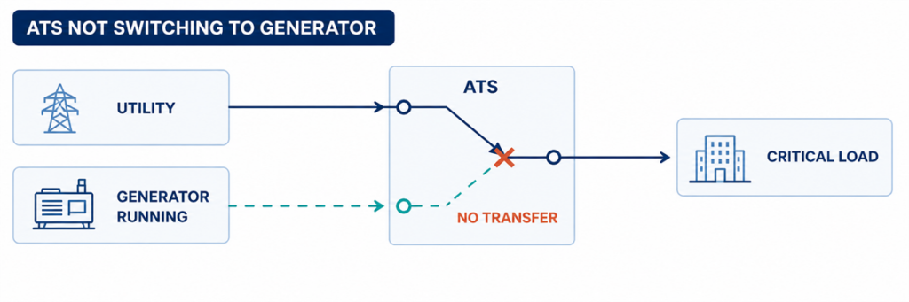
Ang automatic transfer switch ay hindi lumilipat sa generator habang tumatakbo ang generatorKung ang isang automatic transfer switch ay hindi lumilipat sa generator power, hanapin ang unang nabigong hakbang sa pagkakasunod-sunod ng paglipat. Kumpirmahin kung natukoy ng ATS ang isang hindi katanggap-tanggap na utility source, nag-isyu ng engine-start command, nakatanggap ng katanggap-tanggap na generator voltage at frequency, nakumpleto ang naka-program na delay nito, pinaandar ang switching mechanism, at nagbalik ng tamang position feedback. Ang unang nawawalang estado ay karaniwang tumutukoy sa lugar ng sira.
Ang tumatakbong generator ay hindi patunay na handa nang lumipat ang ATS. Maaaring bukas ang generator output breaker, maaaring nasa labas ng controller acceptance window ang voltage o frequency, maaaring may nawawalang phase, maaaring wala ang isang permissive input, o maaaring mabigo ang mechanism pagkatapos mag-isyu ng command ang controller. Mas mabilis ang troubleshooting kapag sinusuri ang mga kondisyong ito nang magkakasunod sa halip na palitan muna ang controller.
Hangganan ng kaligtasan: ang isang ATS enclosure ay maaaring maglaman ng live na utility at generator conductors nang sabay. Maaaring itala ng mga operator ang mga indicator, alarm at controller event nang hindi binubuksan ang mga energized compartment. Ang mga voltage measurement, continuity test, manual mechanism operation at internal inspection ay dapat sumunod sa ordered equipment manual, site switching procedure at naaangkop na mga panuntunan sa electrical-safety, at dapat lamang gawin ng mga kwalipikadong tauhan.
Basahin ang Pagkabigo bilang Isang Naputol na Pagkakasunod-sunod ng Paglipat
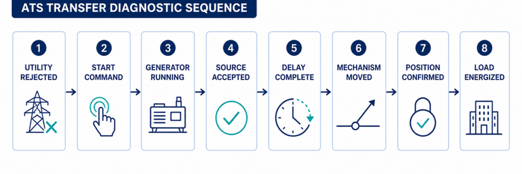
Pagkakasunod-sunod ng ATS diagnostic mula sa utility failure hanggang sa generator load transferAng isang automatic transfer ay isang kadena ng mga desisyon sa halip na isang galaw. Ang isang karaniwang utility-to-generator sequence ay:
- Minomonitor ng controller ang normal source.
- Ang normal source ay nagiging hindi katanggap-tanggap nang mas matagal kaysa sa naka-program na detection delay.
- Binabago ng ATS ang engine-start contact nito upang i-utos ang generator.
- Nagsisimula ang generator at bumubuo ng voltage at frequency sa mga alternate-source terminal ng ATS.
- Tinatanggap ng controller ang alternate source pagkatapos ng stabilization delay nito.
- Pinapayagan ng mga interlock at permissive ang isang transfer command.
- Idinidiskonekta ng mechanism ang normal source at ikinokonekta ang alternate source ayon sa transition design nito.
- Kinukumpirma ng mga auxiliary contact ang bagong posisyon.
- Lumilitaw ang voltage sa mga load terminal at dinadala ng generator ang inilipat na load.
Magsimula sa controller event log at mga front-panel source/position indicator. Isulat ang huling nakumpirmang hakbang. Kung hindi kailanman nakatatanggap ng start request ang generator, hindi malulutas ng pagsisiyasat sa mga power contact ang problema. Kung ipinapakita ng controller na available ang generator ngunit hindi kailanman gumagalaw ang mechanism, hindi rin ito malulutas ng pagbabago sa mga setting ng generator.
Itala ang Mga Parameter na Ito Bago Magbago ng Isang Setting
Ang mga kapaki-pakinabang na parameter ay ang mga value na tumutukoy kung tinatanggap ng controller ang isang source at pinapayagan ang paggalaw. Itala ang kasalukuyang mga setting at naobserbahang value bago gumawa ng anumang pagbabago. Ang mga acceptance window at delay range ay controller- at project-specific; tinutukoy ng talahanayan kung ano ang kukuhanin, hindi mga unibersal na setpoint.
| Parameter | Ano ang itatala | Bakit ito mahalaga | Pinagmulan ng ebidensya |
|---|---|---|---|
| Nominal na boltahe ng pinagmulan | Naka-configure na nominal value at system phase arrangement | Ang maling configuration ay maaaring magmukhang hindi katanggap-tanggap ang isang malusog na source | Naaprubahang settings file, nameplate at one-line diagram |
| Mga limitasyon ng undervoltage at overvoltage | Mga halaga ng pickup/dropout o porsyento na setting para sa bawat source | Ang ATS ay naglilipat lamang pagkatapos lumampas ang boltahe ng source sa naaangkop na limitasyon at delay | Menu ng controller at sequence ng operasyon |
| Mga limitasyon ng frequency | Mga halaga ng pagtanggap ng underfrequency/overfrequency | Ang tumatakbong generator ay maaari pa ring i-reject habang hindi stable ang bilis | Menu ng controller at data ng generator |
| Pagsubaybay sa yugto | Naka-enable ang mga function ng phase loss, phase sequence at phase-unbalance | Ang isang maling kondisyon ng phase ay maaaring humarang sa pagtanggap ng source | Status at mga setting ng controller |
| Delay ng source-failure | Oras mula sa hindi katanggap-tanggap na utility hanggang sa pagkilos ng engine-start | Pinipigilan ang pag-start para sa maikling disturbance | Display ng active-timer at mga aprubadong setting |
| Delay ng generator stabilization | Oras pagkatapos maging katanggap-tanggap ang alternate source bago ang paglipat | Pinapayagan ang boltahe at frequency na tumatag | Timer ng controller at log ng event |
| Timeout ng transfer at mechanism | Pinapayagang oras para sa open/close command at kumpirmasyon ng posisyon | Hinihiwalay ng timeout ang mabagal o bigong galaw mula sa normal na delay | Alarm code, event log at manual ng controller |
| Mga delay ng retransfer at cool-down | Oras ng pag-verify sa pagbalik ng utility at oras ng pagtakbo ng generator nang walang load | Ipinapaliwanag kung bakit nananatili sa generator ang ATS o kung bakit patuloy na tumatakbo ang engine | Mga setting ng controller at generator |
| Logic ng engine-start contact | Close-to-start o open-to-start; mga terminal number at naobserbahang state | Pinipigilan ng hindi tugmang logic na matanggap ng generator ang nilalayong command | Schematic ng ATS at diagram ng remote-start ng generator |
| Kontrol ng suplay | Rated na AC/DC control voltage at value sa panahon ng bigong event | Maaaring i-reset ng pagbaba ng control-voltage ang controller o mapatak ang actuator | Inayos na schematic at kwalipikadong pagsukat |
| Mga permissive at inhibit input | Normal na state at state sa panahon ng bigong transfer | Maaaring sadyang harangan ng external contact ang paggalaw | I/O status screen, PLC/BMS log at wiring diagram |
| Feedback ng posisyon | Normal-open, alternate-closed at intermediate-position na mga contact state | Maaaring tama ang command ng controller ngunit hindi makumpirma ang paggalaw | Controller I/O screen at auxiliary-contact diagram |
| Observed state | Malamang na lugar ng fault | Pinakamahusay na susunod na ebidensya |
|---|---|---|
| Nag-fail ang utility; hindi nag-start ang generator | ATS mode, sensing, start delay, start contact o control wiring | Normal-source status, aktibong timer, start-output indication at generator remote-mode status |
| Tumatakbo ang generator; sinasabi ng ATS na hindi available ang source | Generator output, breaker, boltahe/frequency, phase o sensing circuit | Generator-available indicator, mga reading ng controller at kwalipikadong pagsukat sa mga source terminal |
| Available ang generator; walang transfer command | Delay, inhibit, permissive, test mode o control logic | Aktibong timer, inhibit input, alarm at event log |
| Lumalabas ang transfer command; hindi gumagalaw ang mechanism | Control supply, actuator, coil, motor, interlock o mechanical obstruction | Command output, actuator supply at position feedback |
| Gumagalaw ang mechanism; nananatiling patay ang load | Bukas na generator breaker, sirang contact path, output connection o downstream protection | Posisyon ng ATS, boltahe ng source at load, mga state ng breaker |
| Nangyayari ang transfer; nag-trip ang generator o bumagsak ang boltahe | Load step, kapasidad ng generator, inrush, setting ng protection o problema sa phase | Generator event log, current, frequency at boltahe sa panahon ng transfer |
Kumpirmahin ang Source Recognition mula sa Utility Failure hanggang sa Generator Availability
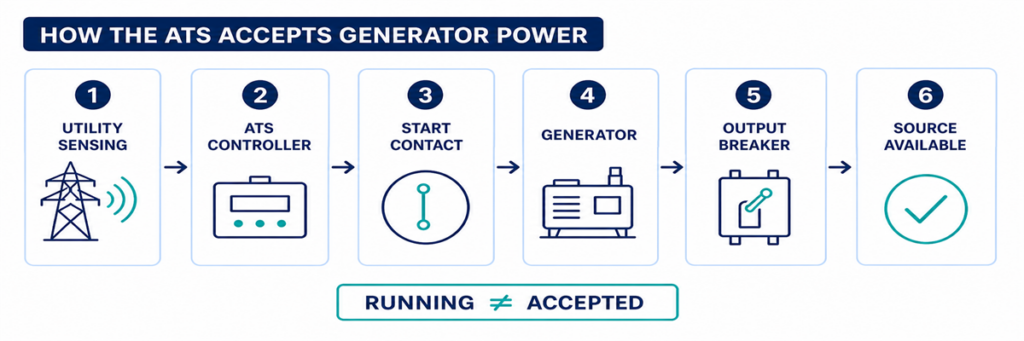
Paano natutukoy at tinatanggap ng ATS ang generator power bago mag-transferCheckpoint 1: Talaga bang Tinanggihan ng ATS ang Utility Source?
Karaniwang nananatili sa utility ang ATS habang itinuturing ng controller na katanggap-tanggap ang source na iyon. Maaaring makakita ang isang facility operator ng madilim na mga ilaw, partial outage o pag-fail ng downstream panel habang ang mga voltage-sensing point sa ATS ay nananatili sa loob ng kanilang naka-program na mga limit. Sa kasong iyon, ang pagtangging mag-transfer ay maaaring tamang pag-uugali sa halip na fault ng ATS.
Check the normal-source indicator and the controller values for each monitored phase. Compare them with the configured undervoltage, overvoltage, frequency, phase-loss and phase-sequence functions for the ordered controller. Also check the time delay on normal-source failure. A short disturbance may disappear before that timer expires, deliberately preventing an unnecessary generator start.
Common reasons the controller still accepts utility
- The outage is downstream of the ATS sensing point.
- Only a circuit or load feeder has failed.
- The undervoltage pickup/dropout setting does not match the intended operating window.
- A sensing fuse or wiring fault gives the controller an incorrect state.
- The controller is reading the wrong nominal-voltage or source configuration.
- The source-failure delay has not expired.
Do not lower a voltage threshold simply to force transfer. First establish the intended source-quality limits and verify that the sensing configuration matches the system. A loose neutral or missing phase can create hazardous voltages that require investigation, not a wider acceptance window.
Checkpoint 2: Was the Generator Start Command Issued?
When the normal source is rejected, many utility-to-generator ATS controllers operate a dry contact connected to the generator remote-start circuit. The contact may close to start or open to start, depending on the generator and ATS design. The two devices must use compatible logic.
First confirm that the ATS is in AUTO or its normal operating mode. Maintenance, monitor, manual, inhibit, fire-control and exercise modes can intentionally block automatic transfer or change the start sequence. Record active alarms and input states before resetting anything; a reset can erase the most useful evidence.
If the controller shows that the start output has operated but the generator remains stopped, inspect the interface between the ATS and generator. Typical causes include an open control conductor, incorrect use of normally open or normally closed terminals, a loose terminal, a blown control fuse, a disabled generator remote mode, low starting-battery voltage or a generator shutdown alarm.
A jumper should not be improvised across start terminals unless the manufacturer’s procedure explicitly requires it and the test is controlled by qualified personnel. Unexpected generator starting can expose people working on the engine, alternator or downstream circuit.
Checkpoint 3: Is Generator Power Reaching the ATS?
A generator can be running while delivering no usable power to the transfer switch. The engine state and alternate-source electrical state are separate checkpoints.
Look for the controller’s generator-available indication. Check whether the generator output breaker is closed and whether any external isolator, feeder breaker or fuse between the generator and ATS is open. Inspect the generator controller for overvoltage, undervoltage, overspeed, underspeed, excitation, phase or breaker-trip alarms.
Where live testing is authorized, qualified personnel should measure the source at the ATS terminals—not only at the generator display. Confirm the correct phase-to-phase and, where applicable, phase-to-neutral voltages, frequency and phase rotation. A good reading at the alternator but no reading at the ATS points to the intervening breaker, cable, termination or protective device.
Why the ATS may reject a running generator
- Voltage remains outside the programmed acceptance band.
- Frequency has not stabilized.
- One phase is absent or the phase sequence is incorrect.
- The controller nominal voltage or sensing ratio is configured incorrectly.
- The generator breaker is open or has tripped.
- A sensing fuse, transformer or harness is open.
- The generator reaches acceptable conditions only briefly and drops out again.
Do not treat the generator’s unloaded panel voltage as final proof. The relevant value is the source condition recognized by the ATS, and later the voltage and frequency retained when the load is applied.
Trace the Transfer Command, Mechanism and Position Feedback
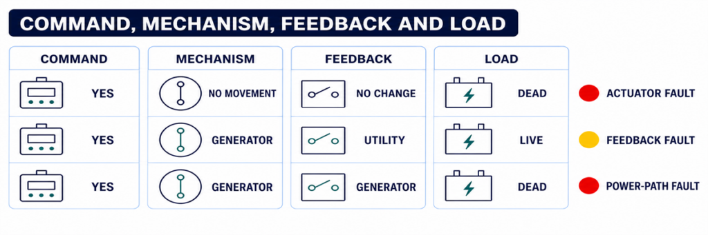
ATS command, switching mechanism, position feedback and load voltage diagnostic comparisonCheckpoint 4: Is a Timer or Permissive Holding the Transfer?
Once the alternate source is acceptable, transfer may still be delayed intentionally. A generator-warm-up timer allows voltage and frequency to stabilize. Other applications require a load-shed confirmation, elevator or motor sequence, UPS status, fire-system input, process permissive, or remote authorization before the switch moves.
Use the controller display to identify which timer is active and whether it is counting. Compare the setting with the approved sequence of operation rather than assuming a delay is excessive. On some controllers a test button or delay-bypass function can shorten a test sequence; this must be used only under the model-specific procedure and when the load is ready to transfer.
If the timer finishes but no command follows, inspect logic inputs for transfer inhibit, emergency inhibit, external trip, source preference, manual retransfer or load-shed confirmation. A permanently energized field contact can make the ATS appear defective while it is obeying the programmed interlock.
Checkpoint 5: Did the Controller Command the Mechanism?
This checkpoint separates a logic problem from an actuator or power-switching problem. Review the event log for commands such as open normal, close alternate, transfer initiated or failure to close. Compare the displayed command with the actual position indicators.
If no command was produced even though source and permissive conditions appear correct, possible causes include an active inhibit, configuration error, failed output, controller power problem or internal controller fault. Verify the controller supply and connectors using the manufacturer’s service instructions before condemning the controller.
If a command was produced, determine whether control voltage reached the relevant motor, solenoid, shunt trip, closing coil or breaker accessory. The exact circuit depends on whether the ATS uses a dedicated switching mechanism, contactors or motorized circuit breakers. Do not apply a generic terminal diagram to a different mechanism.
Checkpoint 6: Can the Switching Mechanism Complete Its Motion?
A controller can issue the correct command while the power mechanism remains in its previous position or stops between positions. Possible causes include:
- missing or low actuator control voltage;
- a blown control fuse or open control transformer secondary;
- a failed motor, solenoid, closing coil or shunt-trip circuit;
- a charged-spring or stored-energy mechanism that is not ready;
- an electrical or mechanical interlock that has not released;
- a breaker that has tripped and requires reset before closing;
- binding, contamination, corrosion or a shipping/maintenance obstruction;
- misaligned or failed limit switches and auxiliary contacts.
Listen for a command and observe the approved external position indication, but do not repeatedly cycle a mechanism that stalls or chatters. Repeated commands can overheat a coil or motor and damage contacts or linkages.
Manual operation is not an ordinary live troubleshooting shortcut. Manufacturer instructions commonly require both utility and generator sources to be isolated before using a manual handle. Follow the exact procedure for the model, verify absence of voltage, and preserve any stored-energy precautions.
Checkpoint 7: Does Position Feedback Agree with the Power Path?
The controller may use auxiliary contacts to prove that one source opened and the other closed. If the mechanism moves but the feedback contact does not change, the controller can report a failed transfer or block the next command. A loose plug, incorrect auxiliary-contact wiring, failed microswitch or mechanical misalignment can create this mismatch.
Compare three independent pieces of evidence:
- the controller’s commanded state;
- the approved mechanical position indicator;
- the electrical state at the load terminals.
These states should agree. If the controller says “load on generator” but the load terminals remain dead, investigate the generator breaker, power contacts, bus connections and downstream protective devices. If load voltage is present but the controller does not confirm position, the feedback circuit is the stronger suspect.
When the ATS Transfers but the Generator Cannot Hold the Load
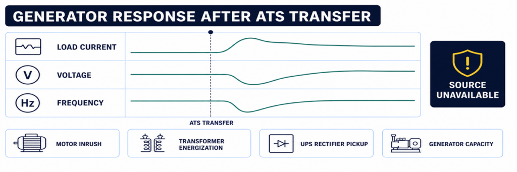
Generator voltage and frequency drop after an automatic transfer switch transfers the loadSome systems complete the movement and then immediately return, trip or lose voltage. That is not the same symptom as “no transfer.” It indicates that the alternate source became unacceptable during or after the load step, or that protection operated.
Review generator voltage, frequency and current trends at the transfer instant. Large motors, transformers, UPS rectifiers and simultaneous load pickup can cause voltage dip or frequency decay. A generator breaker may trip because of overload, short circuit, earth fault or an incorrect protection setting. Phase imbalance or a loose neutral can create a source-quality failure even when total kW appears reasonable.
If the transferred load or generator capacity is uncertain, rebuild the current and load assumptions from the approved load schedule and generator data. The JUTRION generator sizing calculator for ATS backup provides a first-pass check of running load and starting demand. It does not diagnose a control failure, and its result must be verified against the generator manufacturer’s transient-performance data.
Use a Controlled Functional Test to Reproduce the Sequence
A controlled test is more useful than waiting for the next outage. Prepare the load, generator and responsible personnel, then use the test method specified for the ordered ATS. The procedure should verify:
- normal source is initially acceptable and carrying the load;
- the test command initiates the intended engine-start sequence;
- the generator reaches acceptable voltage and frequency;
- the programmed transfer delay operates;
- the mechanism reaches the alternate position;
- the generator carries the intended load without unacceptable voltage or frequency deviation;
- normal-source return and retransfer delay operate;
- the generator completes its cool-down period and stops;
- alarms, event logs, remote indications and position feedback agree throughout.
Do not simulate a failure by disconnecting arbitrary sensing wires or opening energized compartments. Use the controller’s approved test function or the project test procedure. Life-safety, fire-pump, medical, data-centre and continuous-process systems require coordination before any transfer test.
Capture the Evidence Before Resetting or Replacing Parts
Intermittent transfer faults are difficult to diagnose after power has returned and alarms have been cleared. Capture evidence before resetting the system:
- ATS manufacturer, model, controller type and serial number;
- normal and alternate source voltage, frequency and phase configuration;
- controller mode and source-available indicators;
- event and alarm codes with timestamps;
- active delay and its remaining time;
- engine-start output state and generator remote-mode state;
- generator output-breaker position;
- commanded position, mechanical position and feedback state;
- whether the failure occurred unloaded, during transfer or after load pickup;
- recent maintenance, setting changes or wiring work.
This record prevents “controller fault” from becoming the default diagnosis. It also allows a manufacturer or service technician to distinguish an ATS problem from a generator, field-wiring, protection or load problem.
Use the Exact Symptom to Enter the Correct Checkpoint
“The ATS did not transfer” is not specific enough for diagnosis. Record the last state the system completed, then enter the corresponding checkpoint above. This prevents generator, controller and mechanism faults from being mixed together.
| Fault report | First checkpoint | Do not begin by replacing |
|---|---|---|
| Generator did not start | Utility sensing and engine-start output | Power-switching mechanism |
| Generator runs, source unavailable | Generator output at ATS and source settings | ATS main contacts |
| Both sources available, no command | Timers, mode, inhibits and permissives | Generator AVR |
| Command present, no motion | Control power, actuator and interlock | Complete controller without output checks |
| Motion present, wrong status | Auxiliary contacts and position feedback | Generator |
| Transfer followed by collapse | Loaded voltage, frequency, current and protection event | ATS sensing before reviewing the generator event |
| No retransfer to utility | Utility acceptance and return logic | Generator start circuit |
Interpret Controller Indicators Without Treating Them as Measurements
Front-panel indicators are the safest first evidence, but each answers a limited question. A “generator available” LED usually means the controller has accepted the values it senses; it does not prove every phase is present at the load terminals. A “load on generator” indication may be driven by an auxiliary contact; it does not independently measure current flowing to the load.
Use the indicators to form a test hypothesis:
- Normal available: the controller accepts the normal source at its sensing inputs.
- Generator available: alternate-source voltage and frequency have met the configured acceptance logic.
- Engine start active: the controller has commanded its start-output state; field wiring and generator response still require confirmation.
- Transfer timer active: the controller is intentionally waiting, not necessarily stalled.
- Load connected: a position input has changed; verify actual output voltage if the load remains dead.
- Transfer failed: the commanded position was not confirmed within the permitted time.
- Source unavailable: a sensed value is outside acceptance, but the display may not identify whether the cause is the source, sensing circuit or configuration.
If the display provides per-phase voltage and frequency, compare the values with a qualified independent measurement when safe and authorized. A large disagreement points toward sensing wiring, fuses, transformers, selector plugs or configuration. Agreement with an out-of-range value points toward the source itself.
Check Control Power Before Blaming the Controller
A blank screen, intermittent reset or missing output can result from a control-power problem outside the electronic controller. Depending on the ATS design, control power may come from one source, both sources through selection circuitry, a control transformer, a DC supply or an internal power module.
Review the correct schematic and identify which supply should energize the controller at each stage. During a utility failure, an arrangement that normally powers controls from utility must transition to an alternate control source or stored energy. A blown fuse, incorrect transformer tap, loose plug, low DC voltage or failed selector circuit can cause the controller to restart at exactly the time it should transfer.
Evidence of a control-power problem includes:
- display or LEDs resetting when a source fails;
- event-log timestamps restarting;
- relays chattering rather than holding;
- an actuator beginning motion and dropping out;
- normal operation in manual test but failure during a real source interruption;
- different behaviour when the panel door or wiring harness is moved.
Measure control voltage at the condition that produces the fault, not only during stable normal operation. Any live measurement requires appropriate equipment, access boundaries and qualified personnel.
Use Event Timing to Find Intermittent Transfer Failures
An ATS that works during inspection but failed during an outage needs a timeline. Align records from the utility monitor, ATS controller, generator controller, protective devices, BMS or SCADA and critical-load equipment. Even controllers without detailed waveform capture usually preserve enough event order to identify the missing link.
A useful event timeline records:
- the first normal-source abnormality;
- the moment the ATS declared normal unavailable;
- engine-start output operation;
- generator crank and running status;
- alternate-source voltage/frequency available;
- transfer command;
- normal-source open confirmation;
- alternate-source close confirmation;
- load voltage restoration;
- any subsequent trip, retransfer or source-unavailable event.
Timing exposes faults that a static inspection misses. For example, if the generator becomes available for two seconds and then disappears, investigate its stabilization and output. If the transfer command and failed-to-close alarm are separated by the mechanism timeout, investigate actuator power and feedback. If the controller reboots between normal-source loss and engine start, investigate control-power continuity.
Environmental clues matter
Record whether failures coincide with low temperature, high humidity, condensation, dust, vibration, heavy load, battery age or long idle periods. Intermittent connectors, sticky mechanisms, weak starting batteries and enclosure heaters may pass a warm daytime test and fail during an overnight outage. The clue is correlation, not assumption; reproduce the condition safely before replacing parts.
Distinguish an ATS Fault from a Generator or Downstream Fault
The ATS sits between two sources and a load, so symptoms are often assigned to the wrong equipment. Use boundaries at the normal-source terminals, alternate-source terminals and load terminals.
| Evidence | More likely area | Reason |
|---|---|---|
| No start output from ATS after confirmed source failure | ATS sensing, mode, timer or start logic | The generator has not yet been requested to act |
| Start output changes; generator does not crank | Field wiring, generator remote input, battery or generator alarm | The command left the ATS |
| Generator display shows voltage; ATS alternate terminals do not | Generator breaker, feeder or termination | Power is lost between generator and ATS |
| Alternate voltage reaches ATS; controller reads unavailable | Sensing circuit, settings or controller input | Power exists but is not accepted |
| Alternate source accepted; close command absent | ATS logic, delay, inhibit or permissive | The mechanism has not been asked to move |
| Close command and actuator power present; no movement | Actuator, interlock or mechanism | Logic and control delivery are proven |
| ATS load terminals energized; downstream panel dead | Downstream breaker, cable or load system | The transfer switch has delivered power |
This boundary method also improves communication with suppliers. A report stating “generator voltage was present at ATS alternate terminals, controller remained unavailable, settings and sensing fuses checked” is actionable. “ATS does not work” is not.
Verify Retransfer and Cool-Down as Part of the Same System
A complete automatic sequence does not end when the load reaches generator power. When utility returns, the controller normally verifies that it remains acceptable for a return delay, transfers the load back and keeps the generator running unloaded for a cool-down period before releasing the start command.
If utility has returned but the ATS remains on generator, check normal-source acceptance, return delay, manual-retransfer mode, source preference and external inhibit inputs. In applications where return is intentionally supervised, the system may require an operator command even though automatic transfer to generator was permitted.
If the load returns to utility but the generator continues running, determine whether the ATS start contact remains in the run state, whether the field wiring is shorted, or whether the generator’s own cool-down or exercise logic is active. Avoid changing both ATS and generator timers at once; doing so makes the final cause difficult to prove.
Commission the Complete Sequence and Prevent Repeat Failures
Many transfer failures originate at the interface between equipment supplied by different parties. Commissioning must verify the complete chain, not only that each component powers up.
Confirm the source definitions
Record nominal voltage, frequency, phase sequence, neutral arrangement and source preference. Confirm controller sensing selections or transformer taps against the actual system. Verify that both sources and the ATS are compatible before attempting transfer.
Prove the engine-start interface
Document whether the generator expects close-to-start or open-to-start logic and which terminals are used at both ends. Confirm remote mode, conductor continuity and the response to an approved ATS test command.
Prove every timer and inhibit
Record source-failure delay, engine-start delay, generator stabilization, transfer, return and cool-down settings. Operate external inhibit, load-shed and permissive contacts one at a time and verify that controller indication matches the intended sequence.
Prove position and remote status
Verify normal connected, alternate connected, source available, common alarm and transfer-failure outputs at the local display and remote monitoring system. Incorrectly mapped feedback can make a healthy ATS look failed to the BMS—or conceal a real failure.
Test under a representative load
A no-load movement test proves mechanics and part of the control chain, but it does not prove generator response to load pickup or contact-path performance. Where the project procedure permits, perform a representative loaded transfer and record voltage, frequency and current. Stage loads when the approved operating sequence requires it.
Leave a baseline record
Save settings, timer values, event logs, source readings, transfer times and position-feedback states from a successful test. Future technicians can compare a failed event against this known-good sequence rather than relying on memory.
Prevent the Same No-Transfer Fault from Returning
Exercise the complete system at an interval appropriate to the application and local requirements, not only the generator engine. A no-load engine run does not prove that the ATS senses, transfers, carries load, retransfers and stops correctly.
Maintenance should include inspection of control wiring, terminals, fuses, connectors, enclosure condition, heaters where fitted, position indication, mechanical operation under an approved isolated procedure, event logs and generator batteries. Review controller settings after firmware, generator, transformer, protection or load changes.
For projects selecting replacement equipment, confirm source arrangement, voltage, frequency, current, poles and neutral treatment, transfer class, short-circuit coordination, controller I/O and enclosure conditions. Use the JUTRION automatic transfer switch sizing calculator to screen load current, a suitable rating step and the initial pole/configuration questions. It cannot select the final ATS without the fault-current, neutral, transition and controller checks.
After those project inputs are confirmed, compare the result with the JUTRION automatic transfer switch range. The available PC-class, CB-class and controller configurations still have to be matched to the actual source, protection and operating sequence.
Mga Madalas Itanong
Bakit nagsisimula ang generator ngunit hindi naglilipat ang ATS?
Maaaring hindi makita ng ATS ang katanggap-tanggap na boltahe o frequency ng generator, maaaring bukas ang breaker ng generator, maaaring aktibo ang stabilization delay o inhibit, o maaaring mag-utos ang controller ng paglipat habang nabigo ang mekanismo o feedback circuit. Tukuyin ang unang nawawalang estado sa pagkakasunod-sunod ng paglipat.
Maaari ko bang manual na ilipat ang isang ATS sa generator power?
Sa ilalim lamang ng pamamaraang tukoy sa modelo ng tagagawa. Maraming transfer switch ang nangangailangan na kapwa pinagmumulan ay idiskonekta bago ang manwal na operasyon. Huwag kailanman gamitin ang manwal na hawakan bilang isang shortcut sa live na pag-troubleshoot.
Bakit nagta-transfer ang ATS at pagkatapos ay agad na bumabalik?
Maaaring lumabas ang pinagmumulan ng generator sa labas ng window ng pagtanggap ng boltahe o frequency nito kapag inilapat ang load, o maaaring gumana ang breaker/proteksyon ng generator. Suriin ang event log at ang pag-uugali ng generator habang isinasagawa ang load step.
Maaari bang pigilan ng maling setting ng time-delay ang isang ATS sa paglilipat?
Oo. Ang mga pagkaantala sa pagkabigo-ng-pinagmulan, pag-andar-ng-makina, pagpapatatag-ng-generator at paglilipat ay maaaring magmukhang natigil ang isang tamang pagkakasunod-sunod. Ang isang aktibong inhibit o permissive ay maaari ring humarang sa paglilipat pagkatapos matapos ang timer.
Nangangahulugan ba ang blangkong ATS controller na tuluyan nang nasira ang switch?
Hindi naman kinakailangan. Ang nawawalang power ng controller, bukas na control fuse, problema sa transformer o harness ay maaaring mag-blangko ng display. I-verify ang control-power path ayon sa service procedure ng manufacturer bago palitan ang controller.
Finish the Diagnosis at the First Missing State
Do not begin with the most expensive component. Begin with the sequence. If the ATS never rejects utility, investigate sensing and settings. If it rejects utility but never requests a start, investigate mode, timers and the start circuit. If the generator runs but remains unavailable, investigate its electrical output and the ATS sensing path. If the source is accepted but the switch does not move, investigate permissives, control power, actuator and interlocks. If the mechanism moves but the load remains dead, verify the power path and feedback.
That evidence-led order shortens downtime and avoids replacing a controller for a generator breaker, a mechanism for an active inhibit, or an entire ATS for one open control conductor.
