

Quick Answer: Why Is the Automatic Transfer Switch Not Switching to the Generator?
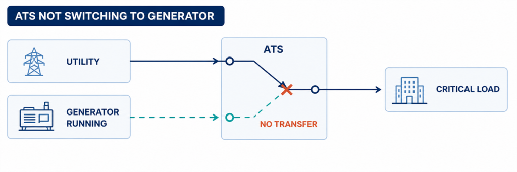
Automatic transfer switch not switching to the generator while the generator is runningIf an automatic transfer switch is not switching to generator power, find the first failed step in the transfer sequence. Confirm whether the ATS detected an unacceptable utility source, issued the engine-start command, received acceptable generator voltage and frequency, completed its programmed delay, operated the switching mechanism, and returned the correct position feedback. The first missing state normally identifies the fault area.
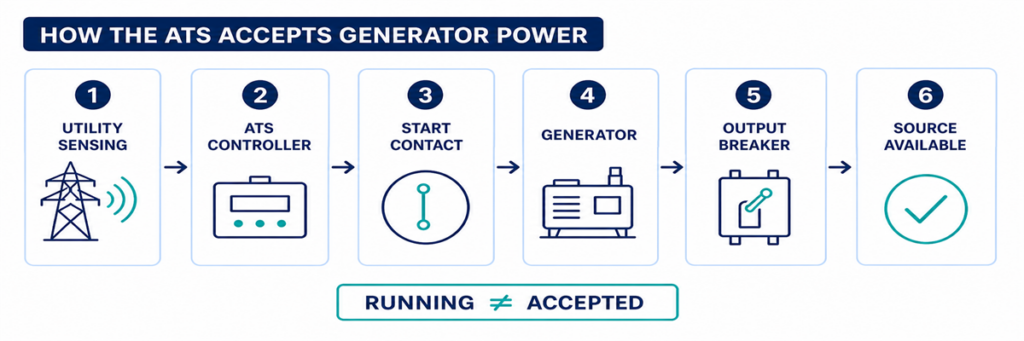
A running generator does not prove that the ATS is ready to transfer. The generator output breaker may be open, voltage or frequency may remain outside the controller acceptance window, a phase may be missing, a permissive input may be absent, or the mechanism may fail after the controller issues the command. Troubleshooting becomes faster when these conditions are checked in sequence instead of replacing the controller first.
Safety boundary: an ATS enclosure can contain live utility and generator conductors at the same time. Operators may record indicators, alarms and controller events without opening energized compartments. Voltage measurements, continuity tests, manual mechanism operation and internal inspection must follow the ordered equipment manual, site switching procedure and applicable electrical-safety rules, and should be performed only by qualified personnel.
Read the Failure as a Broken Transfer Sequence
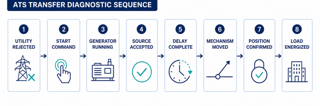
ATS diagnostic sequence from utility failure to generator load transferAn automatic transfer is a chain of decisions rather than one movement. A typical utility-to-generator sequence is:
- පාලකය සාමාන්ය ප්රභවය නිරීක්ෂණය කරයි.
- සාමාන්ය ප්රභවය වැඩසටහන්ගත හඳුනාගැනීමේ ප්රමාදයට වඩා වැඩි කාලයක් පිළිගත නොහැකි තත්ත්වයක පවතී.
- ATS ජනක යන්ත්රයට විධාන කිරීම සඳහා එහි එන්ජින්-ආරම්භක ස්පර්ශය වෙනස් කරයි.
- ජනක යන්ත්රය ආරම්භ වී ATS විකල්ප-ප්රභව පර්යන්තවල වෝල්ටීයතාව සහ සංඛ්යාතය වර්ධනය කරයි.
- පාලකය එහි ස්ථායීකරණ ප්රමාදයෙන් පසු විකල්ප ප්රභවය පිළිගනී.
- අන්තර් අගුල් සහ අවසරයන් මාරු කිරීමේ විධානයකට ඉඩ සලසයි.
- යාන්ත්රණය එහි සංක්රාන්ති සැලසුමට අනුව සාමාන්ය ප්රභවය විසන්ධි කර විකල්ප ප්රභවය සම්බන්ධ කරයි.
- සහායක ස්පර්ශ නව ස්ථානය තහවුරු කරයි.
- භාර පර්යන්තවල වෝල්ටීයතාව දිස්වන අතර ජනක යන්ත්රය මාරු කළ භාරය උසුලයි.
පාලක සිදුවීම් ලොගය සහ ඉදිරිපස පුවරු ප්රභව/ස්ථාන දර්ශක වලින් ආරම්භ කරන්න. අවසන් තහවුරු කළ පියවර ලියා තබන්න. ජනක යන්ත්රයට කිසිදු ආරම්භක ඉල්ලීමක් නොලැබුනේ නම්, බල ස්පර්ශ පරීක්ෂා කිරීමෙන් ගැටළුව විසඳෙන්නේ නැත. පාලකය ජනක යන්ත්රය ලබා ගත හැකි ලෙස පෙන්වන නමුත් යාන්ත්රණය කිසිදා චලනය නොවන්නේ නම්, ජනක සැකසුම් වෙනස් කිරීමෙන්ද එය විසඳෙන්නේ නැත.
සැකසුමක් වෙනස් කිරීමට පෙර මෙම පරාමිතීන් සටහන් කරන්න
ප්රයෝජනවත් පරාමිතීන් යනු පාලකය ප්රභවයක් පිළිගන්නේද සහ චලනයට ඉඩ දෙන්නේද යන්න තීරණය කරන අගයන්ය. කිසියම් වෙනසක් කිරීමට පෙර වත්මන් සැකසුම් සහ නිරීක්ෂිත අගයන් සටහන් කරන්න. පිළිගැනීමේ කවුළු සහ ප්රමාද පරාස පාලක- සහ ව්යාපෘති-විශේෂිත වේ; වගුව හඳුනා ගත යුතු දේ හඳුනා ගනී, විශ්වීය ස්ථාපිත ලක්ෂ්ය නොවේ.
| Paramèt | සටහන් කළ යුතු දේ | ហេតុអ្វីវាសំខាន់ | සාක්ෂි ප්රභවය |
|---|---|---|---|
| නාමික ප්රභව වෝල්ටීයතාව | වින්යාසගත නාමික අගය සහ පද්ධති අවධි සැකැස්ම | වැරදි වින්යාසයක් නිරෝගී ප්රභවයක් පිළිගත නොහැකි ලෙස පෙනෙන්නට සැලැස්විය හැක | අනුමත සැකසුම් ගොනුව, නාම පුවරුව සහ ඒක-රේඛා රූප සටහන |
| අඩු වෝල්ටීයතා සහ අධි වෝල්ටීයතා සීමාවන් | එක් එක් ප්රභවය සඳහා ග්රහණ/අතහැරීම් අගයන් හෝ ප්රතිශත සැකසුම් | ATS ផ្ទេរតែបន្ទាប់ពីវ៉ុលប្រភពឆ្លងកាត់ដែនកំណត់ដែលអាចអនុវត្តបាន និងការពន្យារពេល | ម៉ឺនុយឧបករណ៍បញ្ជា និងលំដាប់ប្រតិបត្តិការ |
| ដែនកំណត់ប្រេកង់ | តម្លៃទទួលយកប្រេកង់ក្រោម/លើស | ម៉ាស៊ីនភ្លើងដែលកំពុងដំណើរការអាចនៅតែត្រូវបានបដិសេធ ខណៈល្បឿនមិនស្ថិតស្ថេរ | ម៉ឺនុយឧបករណ៍បញ្ជា និងទិន្នន័យម៉ាស៊ីនភ្លើង |
| ការត្រួតពិនិត្យដំណាក់កាល | មុខងារបាត់បង់ដំណាក់កាល លំដាប់ដំណាក់កាល និងអតុល្យភាពដំណាក់កាលត្រូវបានបើកដំណើរការ | លក្ខខណ្ឌដំណាក់កាលមិនត្រឹមត្រូវមួយអាចរារាំងការទទួលយកប្រភព | ស្ថានភាពឧបករណ៍បញ្ជា និងការកំណត់ |
| ការពន្យារពេលបរាជ័យប្រភព | ពេលវេលាពីឧបករណ៍ប្រើប្រាស់មិនអាចទទួលយកបាន ដល់សកម្មភាពចាប់ផ្តើមម៉ាស៊ីន | ការពារការចាប់ផ្តើមសម្រាប់ការរំខានរយៈពេលខ្លី | ការបង្ហាញកម្មវិធីកំណត់ពេលសកម្ម និងការកំណត់ដែលបានអនុម័ត |
| ការពន្យារពេលស្ថេរភាពម៉ាស៊ីនភ្លើង | ពេលវេលាបន្ទាប់ពីប្រភពជំនួសអាចទទួលយកបាន មុនពេលផ្ទេរ | អនុញ្ញាតឱ្យវ៉ុល និងប្រេកង់មានស្ថេរភាព | កម្មវិធីកំណត់ពេលឧបករណ៍បញ្ជា និងកំណត់ហេតុព្រឹត្តិការណ៍ |
| ការផ្ទេរ និងការអស់ពេលយន្តការ | ពេលវេលាអនុញ្ញាតសម្រាប់ពាក្យបញ្ជាបើក/បិទ និងការបញ្ជាក់ទីតាំង | ការអស់ពេលបំបែកចលនាយឺត ឬបរាជ័យពីការពន្យារពេលធម្មតា | Kòd alam, jounal evènman ak manyèl kontwolè a |
| Reta retransfè ak refwadisman | Tan verifikasyon retou rezo a ak tan fonksyonman dèlko san chaj | Eksplike poukisa ATS la rete sou dèlko oswa poukisa motè a kontinye mache | Paramèt kontwolè ak dèlko |
| Lojik kontak demaraj motè a | Fèmen-pou-kòmanse oswa ouvè-pou-kòmanse; nimewo tèminal ak eta obsève | Lojik enkonpatib anpeche dèlko a resevwa kòmandman an gen entansyon | Schéma ATS ak dyagram demaraj aleka dèlko a |
| Alimantasyon kontwòl | Vòltaj kontwòl AC/DC nominal ak valè pandan evènman echèk la | Yon bès vòltaj kontwòl ka reyinisyalize kontwolè a oswa lage actuateur a | Schéma kòmande ak mezi kalifye |
| Antre pèmisif ak anpèchman | Eta nòmal ak eta pandan transfè echwe a | Yon kontak ekstèn ka entansyonèlman bloke mouvman an | Ekran estati I/O, jounal PLC/BMS ak dyagram filaj |
| Feedback pozisyon | Eta kontak nòmal-ouvè, altènatif-fèmen ak pozisyon entèmedyè | Kontwolè a ka bay kòmandman kòrèkteman men li pa konfime mouvman an | Ekran I/O kontwolè a ak dyagram kontak oksilyè |
| Observed state | Zòn fay posib | Pi bon prèv pwochen |
|---|---|---|
| Rezo a echwe; dèlko a pa kòmanse | Mòd ATS, deteksyon, reta demaraj, kontak demaraj oswa filaj kontwòl | Estati sous nòmal, minitè aktif, endikasyon sòti demaraj ak estati mòd aleka dèlko a |
| Dèlko a mache; ATS di sous la pa disponib | Sòti dèlko, disjoncteur, vòltaj/frekans, faz oswa sikwi deteksyon | Endikatè dèlko-disponib, lekti kontwolè ak mezi kalifye nan tèminal sous yo |
| Dèlko a disponib; pa gen kòmandman transfè | Reta, anpèchman, pèmisif, mòd tès oswa lojik kontwòl | Minitè aktif, antre anpèchman, alam ak jounal evènman |
| Kòmandman transfè parèt; mekanis la pa deplase | Alimantasyon kontwòl, actuateur, bobin, motè, verouyaj oswa obstak mekanik | የትእዛዝ ውጤት፣ የአንቀሳቃሽ አቅርቦት እና የአቀማመጥ ምላሽ |
| ሜካኒዝም ይንቀሳቀሳል፤ ጭነቱ ሳይነቃነቅ ይቀራል | የጄነሬተር መግቻን ይክፈቱ፣ የተበላሸ የግንኙነት መንገድ፣ የውጤት ግንኙነት ወይም የታችኛው ጥበቃ | የATS አቀማመጥ፣ የምንጭ እና የጭነት ቮልቴጅ፣ የመግቻ ሁኔታዎች |
| ሽግግር ይከሰታል፤ ጄነሬተር ይዘጋል ወይም ቮልቴጅ ይወድቃል | የጭነት ደረጃ፣ የጄነሬተር አቅም፣ የመነሻ ጅረት፣ የጥበቃ ቅንብር ወይም የደረጃ ችግር | የጄነሬተር ክስተት መዝገብ፣ ጅረት፣ ድግግሞሽ እና ቮልቴጅ በሽግግሩ ወቅት |
ከመገልገያ ውድቀት እስከ ጄነሬተር ዝግጁነት ድረስ የምንጭ ማወቂያን ያረጋግጡ
ኤቲኤስ ከማስተላለፉ በፊት የጄነሬተር ኃይልን እንዴት እንደሚያውቅ እና እንደሚቀበልፍተሻ 1፡ ኤቲኤስ የመገልገያ ምንጩን በእርግጥ ውድቅ አድርጎታል?
ኤቲኤስ በመደበኛነት በመገልገያ ላይ ይቆያል፣ ተቆጣጣሪው ምንጩን ተቀባይነት እንዳለው እስካሰበ ድረስ። የፋብሪካ ኦፕሬተር ደብዛዛ መብራቶችን፣ ከፊል የኃይል መቋረጥን ወይም የታችኛው ፓነል ውድቀትን ሊያይ ይችላል፣ በኤቲኤስ ላይ ያሉት የቮልቴጅ ዳሳሽ ነጥቦች በፕሮግራም በተደነገጉት ገደቦች ውስጥ ሲቆዩ። በዚህ ሁኔታ፣ ለማስተላለፍ አለመቀበል የኤቲኤስ ጉድለት ሳይሆን ትክክለኛ ባህሪ ሊሆን ይችላል።.
የመደበኛ ምንጭ አመልካቹን እና ለእያንዳንዱ ክትትል የሚደረግለትን ደረጃ የተቆጣጣሪ እሴቶችን ይፈትሹ። ከታዘዘው ተቆጣጣሪ ጋር ከተዋቀሩት የዝቅተኛ ቮልቴጅ፣ የከፍተኛ ቮልቴጅ፣ የድግግሞሽ፣ የደረጃ መጥፋት እና የደረጃ ቅደም ተከተል ተግባራት ጋር ያወዳድሩ። እንዲሁም በመደበኛ ምንጭ ውድቀት ላይ ያለውን የጊዜ መዘግየት ይፈትሹ። አጭር መዛባት ያ ሰዓት ቆጣሪ ከማለቁ በፊት ሊጠፋ ይችላል፣ ይህም ሆን ተብሎ አላስፈላጊ የጄነሬተር ጅምርን ይከላከላል።.
ተቆጣጣሪው አሁንም መገልገያን የሚቀበልባቸው የተለመዱ ምክንያቶች
- የኃይል መቋረጡ ከኤቲኤስ ዳሳሽ ነጥብ በታች ነው።.
- የወረዳ ወይም የጭነት መጋቢ ብቻ ነው የወደቀው።.
- የዝቅተኛ ቮልቴጅ ማንሳት/መውረድ ቅንብር ከታሰበው የስራ መስኮት ጋር አይዛመድም።.
- A sensing fuse or wiring fault gives the controller an incorrect state.
- The controller is reading the wrong nominal-voltage or source configuration.
- The source-failure delay has not expired.
Do not lower a voltage threshold simply to force transfer. First establish the intended source-quality limits and verify that the sensing configuration matches the system. A loose neutral or missing phase can create hazardous voltages that require investigation, not a wider acceptance window.
Checkpoint 2: Was the Generator Start Command Issued?
When the normal source is rejected, many utility-to-generator ATS controllers operate a dry contact connected to the generator remote-start circuit. The contact may close to start or open to start, depending on the generator and ATS design. The two devices must use compatible logic.
First confirm that the ATS is in AUTO or its normal operating mode. Maintenance, monitor, manual, inhibit, fire-control and exercise modes can intentionally block automatic transfer or change the start sequence. Record active alarms and input states before resetting anything; a reset can erase the most useful evidence.
If the controller shows that the start output has operated but the generator remains stopped, inspect the interface between the ATS and generator. Typical causes include an open control conductor, incorrect use of normally open or normally closed terminals, a loose terminal, a blown control fuse, a disabled generator remote mode, low starting-battery voltage or a generator shutdown alarm.
A jumper should not be improvised across start terminals unless the manufacturer’s procedure explicitly requires it and the test is controlled by qualified personnel. Unexpected generator starting can expose people working on the engine, alternator or downstream circuit.
Checkpoint 3: Is Generator Power Reaching the ATS?
A generator can be running while delivering no usable power to the transfer switch. The engine state and alternate-source electrical state are separate checkpoints.
Look for the controller’s generator-available indication. Check whether the generator output breaker is closed and whether any external isolator, feeder breaker or fuse between the generator and ATS is open. Inspect the generator controller for overvoltage, undervoltage, overspeed, underspeed, excitation, phase or breaker-trip alarms.
Where live testing is authorized, qualified personnel should measure the source at the ATS terminals—not only at the generator display. Confirm the correct phase-to-phase and, where applicable, phase-to-neutral voltages, frequency and phase rotation. A good reading at the alternator but no reading at the ATS points to the intervening breaker, cable, termination or protective device.
Why the ATS may reject a running generator
- Voltage remains outside the programmed acceptance band.
- Frequency has not stabilized.
- One phase is absent or the phase sequence is incorrect.
- The controller nominal voltage or sensing ratio is configured incorrectly.
- The generator breaker is open or has tripped.
- A sensing fuse, transformer or harness is open.
- The generator reaches acceptable conditions only briefly and drops out again.
Do not treat the generator’s unloaded panel voltage as final proof. The relevant value is the source condition recognized by the ATS, and later the voltage and frequency retained when the load is applied.
Trace the Transfer Command, Mechanism and Position Feedback
ATS command, switching mechanism, position feedback and load voltage diagnostic comparisonCheckpoint 4: Is a Timer or Permissive Holding the Transfer?
Once the alternate source is acceptable, transfer may still be delayed intentionally. A generator-warm-up timer allows voltage and frequency to stabilize. Other applications require a load-shed confirmation, elevator or motor sequence, UPS status, fire-system input, process permissive, or remote authorization before the switch moves.
Use the controller display to identify which timer is active and whether it is counting. Compare the setting with the approved sequence of operation rather than assuming a delay is excessive. On some controllers a test button or delay-bypass function can shorten a test sequence; this must be used only under the model-specific procedure and when the load is ready to transfer.
If the timer finishes but no command follows, inspect logic inputs for transfer inhibit, emergency inhibit, external trip, source preference, manual retransfer or load-shed confirmation. A permanently energized field contact can make the ATS appear defective while it is obeying the programmed interlock.
Checkpoint 5: Did the Controller Command the Mechanism?
This checkpoint separates a logic problem from an actuator or power-switching problem. Review the event log for commands such as open normal, close alternate, transfer initiated or failure to close. Compare the displayed command with the actual position indicators.
If no command was produced even though source and permissive conditions appear correct, possible causes include an active inhibit, configuration error, failed output, controller power problem or internal controller fault. Verify the controller supply and connectors using the manufacturer’s service instructions before condemning the controller.
If a command was produced, determine whether control voltage reached the relevant motor, solenoid, shunt trip, closing coil or breaker accessory. The exact circuit depends on whether the ATS uses a dedicated switching mechanism, contactors or motorized circuit breakers. Do not apply a generic terminal diagram to a different mechanism.
Checkpoint 6: Can the Switching Mechanism Complete Its Motion?
A controller can issue the correct command while the power mechanism remains in its previous position or stops between positions. Possible causes include:
- missing or low actuator control voltage;
- a blown control fuse or open control transformer secondary;
- a failed motor, solenoid, closing coil or shunt-trip circuit;
- a charged-spring or stored-energy mechanism that is not ready;
- an electrical or mechanical interlock that has not released;
- a breaker that has tripped and requires reset before closing;
- binding, contamination, corrosion or a shipping/maintenance obstruction;
- misaligned or failed limit switches and auxiliary contacts.
Listen for a command and observe the approved external position indication, but do not repeatedly cycle a mechanism that stalls or chatters. Repeated commands can overheat a coil or motor and damage contacts or linkages.
Manual operation is not an ordinary live troubleshooting shortcut. Manufacturer instructions commonly require both utility and generator sources to be isolated before using a manual handle. Follow the exact procedure for the model, verify absence of voltage, and preserve any stored-energy precautions.
Checkpoint 7: Does Position Feedback Agree with the Power Path?
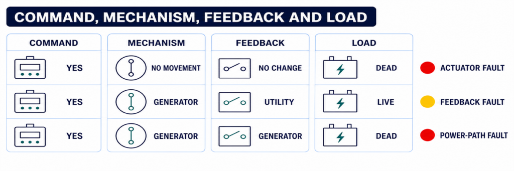
The controller may use auxiliary contacts to prove that one source opened and the other closed. If the mechanism moves but the feedback contact does not change, the controller can report a failed transfer or block the next command. A loose plug, incorrect auxiliary-contact wiring, failed microswitch or mechanical misalignment can create this mismatch.
Compare three independent pieces of evidence:
- the controller’s commanded state;
- the approved mechanical position indicator;
- the electrical state at the load terminals.
These states should agree. If the controller says “load on generator” but the load terminals remain dead, investigate the generator breaker, power contacts, bus connections and downstream protective devices. If load voltage is present but the controller does not confirm position, the feedback circuit is the stronger suspect.
When the ATS Transfers but the Generator Cannot Hold the Load
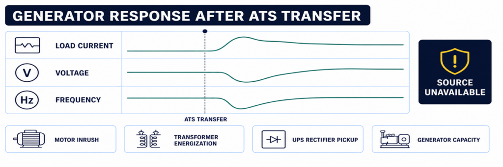
Generator voltage and frequency drop after an automatic transfer switch transfers the loadSome systems complete the movement and then immediately return, trip or lose voltage. That is not the same symptom as “no transfer.” It indicates that the alternate source became unacceptable during or after the load step, or that protection operated.
Review generator voltage, frequency and current trends at the transfer instant. Large motors, transformers, UPS rectifiers and simultaneous load pickup can cause voltage dip or frequency decay. A generator breaker may trip because of overload, short circuit, earth fault or an incorrect protection setting. Phase imbalance or a loose neutral can create a source-quality failure even when total kW appears reasonable.
If the transferred load or generator capacity is uncertain, rebuild the current and load assumptions from the approved load schedule and generator data. The JUTRION generator sizing calculator for ATS backup provides a first-pass check of running load and starting demand. It does not diagnose a control failure, and its result must be verified against the generator manufacturer’s transient-performance data.
Use a Controlled Functional Test to Reproduce the Sequence
A controlled test is more useful than waiting for the next outage. Prepare the load, generator and responsible personnel, then use the test method specified for the ordered ATS. The procedure should verify:
- normal source is initially acceptable and carrying the load;
- the test command initiates the intended engine-start sequence;
- the generator reaches acceptable voltage and frequency;
- the programmed transfer delay operates;
- the mechanism reaches the alternate position;
- the generator carries the intended load without unacceptable voltage or frequency deviation;
- normal-source return and retransfer delay operate;
- the generator completes its cool-down period and stops;
- alarms, event logs, remote indications and position feedback agree throughout.
Do not simulate a failure by disconnecting arbitrary sensing wires or opening energized compartments. Use the controller’s approved test function or the project test procedure. Life-safety, fire-pump, medical, data-centre and continuous-process systems require coordination before any transfer test.
Capture the Evidence Before Resetting or Replacing Parts
Intermittent transfer faults are difficult to diagnose after power has returned and alarms have been cleared. Capture evidence before resetting the system:
- ATS manufacturer, model, controller type and serial number;
- normal and alternate source voltage, frequency and phase configuration;
- controller mode and source-available indicators;
- event and alarm codes with timestamps;
- active delay and its remaining time;
- engine-start output state and generator remote-mode state;
- generator output-breaker position;
- commanded position, mechanical position and feedback state;
- whether the failure occurred unloaded, during transfer or after load pickup;
- recent maintenance, setting changes or wiring work.
This record prevents “controller fault” from becoming the default diagnosis. It also allows a manufacturer or service technician to distinguish an ATS problem from a generator, field-wiring, protection or load problem.
Use the Exact Symptom to Enter the Correct Checkpoint
“The ATS did not transfer” is not specific enough for diagnosis. Record the last state the system completed, then enter the corresponding checkpoint above. This prevents generator, controller and mechanism faults from being mixed together.
| Fault report | First checkpoint | Do not begin by replacing |
|---|---|---|
| Generator did not start | Utility sensing and engine-start output | Power-switching mechanism |
| Generator runs, source unavailable | Generator output at ATS and source settings | ATS main contacts |
| Both sources available, no command | Timers, mode, inhibits and permissives | Generator AVR |
| Command present, no motion | Control power, actuator and interlock | Complete controller without output checks |
| Motion present, wrong status | Auxiliary contacts and position feedback | Generator |
| Transfer followed by collapse | Loaded voltage, frequency, current and protection event | ATS sensing before reviewing the generator event |
| No retransfer to utility | Utility acceptance and return logic | Generator start circuit |
Interpret Controller Indicators Without Treating Them as Measurements
Front-panel indicators are the safest first evidence, but each answers a limited question. A “generator available” LED usually means the controller has accepted the values it senses; it does not prove every phase is present at the load terminals. A “load on generator” indication may be driven by an auxiliary contact; it does not independently measure current flowing to the load.
Use the indicators to form a test hypothesis:
- Normal available: the controller accepts the normal source at its sensing inputs.
- Generator available: alternate-source voltage and frequency have met the configured acceptance logic.
- Engine start active: the controller has commanded its start-output state; field wiring and generator response still require confirmation.
- Transfer timer active: the controller is intentionally waiting, not necessarily stalled.
- Load connected: a position input has changed; verify actual output voltage if the load remains dead.
- Transfer failed: the commanded position was not confirmed within the permitted time.
- Source unavailable: a sensed value is outside acceptance, but the display may not identify whether the cause is the source, sensing circuit or configuration.
If the display provides per-phase voltage and frequency, compare the values with a qualified independent measurement when safe and authorized. A large disagreement points toward sensing wiring, fuses, transformers, selector plugs or configuration. Agreement with an out-of-range value points toward the source itself.
Check Control Power Before Blaming the Controller
A blank screen, intermittent reset or missing output can result from a control-power problem outside the electronic controller. Depending on the ATS design, control power may come from one source, both sources through selection circuitry, a control transformer, a DC supply or an internal power module.
Review the correct schematic and identify which supply should energize the controller at each stage. During a utility failure, an arrangement that normally powers controls from utility must transition to an alternate control source or stored energy. A blown fuse, incorrect transformer tap, loose plug, low DC voltage or failed selector circuit can cause the controller to restart at exactly the time it should transfer.
Evidence of a control-power problem includes:
- display or LEDs resetting when a source fails;
- event-log timestamps restarting;
- relays chattering rather than holding;
- an actuator beginning motion and dropping out;
- normal operation in manual test but failure during a real source interruption;
- different behaviour when the panel door or wiring harness is moved.
Measure control voltage at the condition that produces the fault, not only during stable normal operation. Any live measurement requires appropriate equipment, access boundaries and qualified personnel.
Use Event Timing to Find Intermittent Transfer Failures
An ATS that works during inspection but failed during an outage needs a timeline. Align records from the utility monitor, ATS controller, generator controller, protective devices, BMS or SCADA and critical-load equipment. Even controllers without detailed waveform capture usually preserve enough event order to identify the missing link.
A useful event timeline records:
- the first normal-source abnormality;
- the moment the ATS declared normal unavailable;
- engine-start output operation;
- generator crank and running status;
- alternate-source voltage/frequency available;
- transfer command;
- normal-source open confirmation;
- alternate-source close confirmation;
- load voltage restoration;
- any subsequent trip, retransfer or source-unavailable event.
Timing exposes faults that a static inspection misses. For example, if the generator becomes available for two seconds and then disappears, investigate its stabilization and output. If the transfer command and failed-to-close alarm are separated by the mechanism timeout, investigate actuator power and feedback. If the controller reboots between normal-source loss and engine start, investigate control-power continuity.
Environmental clues matter
Record whether failures coincide with low temperature, high humidity, condensation, dust, vibration, heavy load, battery age or long idle periods. Intermittent connectors, sticky mechanisms, weak starting batteries and enclosure heaters may pass a warm daytime test and fail during an overnight outage. The clue is correlation, not assumption; reproduce the condition safely before replacing parts.
Distinguish an ATS Fault from a Generator or Downstream Fault
The ATS sits between two sources and a load, so symptoms are often assigned to the wrong equipment. Use boundaries at the normal-source terminals, alternate-source terminals and load terminals.
| Evidence | More likely area | Reason |
|---|---|---|
| No start output from ATS after confirmed source failure | ATS sensing, mode, timer or start logic | The generator has not yet been requested to act |
| Start output changes; generator does not crank | Field wiring, generator remote input, battery or generator alarm | The command left the ATS |
| Generator display shows voltage; ATS alternate terminals do not | Generator breaker, feeder or termination | Power is lost between generator and ATS |
| Alternate voltage reaches ATS; controller reads unavailable | Sensing circuit, settings or controller input | Power exists but is not accepted |
| Alternate source accepted; close command absent | ATS logic, delay, inhibit or permissive | The mechanism has not been asked to move |
| Close command and actuator power present; no movement | Actuator, interlock or mechanism | Logic and control delivery are proven |
| ATS load terminals energized; downstream panel dead | Downstream breaker, cable or load system | The transfer switch has delivered power |
This boundary method also improves communication with suppliers. A report stating “generator voltage was present at ATS alternate terminals, controller remained unavailable, settings and sensing fuses checked” is actionable. “ATS does not work” is not.
Verify Retransfer and Cool-Down as Part of the Same System
A complete automatic sequence does not end when the load reaches generator power. When utility returns, the controller normally verifies that it remains acceptable for a return delay, transfers the load back and keeps the generator running unloaded for a cool-down period before releasing the start command.
If utility has returned but the ATS remains on generator, check normal-source acceptance, return delay, manual-retransfer mode, source preference and external inhibit inputs. In applications where return is intentionally supervised, the system may require an operator command even though automatic transfer to generator was permitted.
If the load returns to utility but the generator continues running, determine whether the ATS start contact remains in the run state, whether the field wiring is shorted, or whether the generator’s own cool-down or exercise logic is active. Avoid changing both ATS and generator timers at once; doing so makes the final cause difficult to prove.
Commission the Complete Sequence and Prevent Repeat Failures
Many transfer failures originate at the interface between equipment supplied by different parties. Commissioning must verify the complete chain, not only that each component powers up.
Confirm the source definitions
Record nominal voltage, frequency, phase sequence, neutral arrangement and source preference. Confirm controller sensing selections or transformer taps against the actual system. Verify that both sources and the ATS are compatible before attempting transfer.
Prove the engine-start interface
Document whether the generator expects close-to-start or open-to-start logic and which terminals are used at both ends. Confirm remote mode, conductor continuity and the response to an approved ATS test command.
Prove every timer and inhibit
Record source-failure delay, engine-start delay, generator stabilization, transfer, return and cool-down settings. Operate external inhibit, load-shed and permissive contacts one at a time and verify that controller indication matches the intended sequence.
Prove position and remote status
Verify normal connected, alternate connected, source available, common alarm and transfer-failure outputs at the local display and remote monitoring system. Incorrectly mapped feedback can make a healthy ATS look failed to the BMS—or conceal a real failure.
Test under a representative load
A no-load movement test proves mechanics and part of the control chain, but it does not prove generator response to load pickup or contact-path performance. Where the project procedure permits, perform a representative loaded transfer and record voltage, frequency and current. Stage loads when the approved operating sequence requires it.
Leave a baseline record
Save settings, timer values, event logs, source readings, transfer times and position-feedback states from a successful test. Future technicians can compare a failed event against this known-good sequence rather than relying on memory.
Prevent the Same No-Transfer Fault from Returning
Exercise the complete system at an interval appropriate to the application and local requirements, not only the generator engine. A no-load engine run does not prove that the ATS senses, transfers, carries load, retransfers and stops correctly.
Maintenance should include inspection of control wiring, terminals, fuses, connectors, enclosure condition, heaters where fitted, position indication, mechanical operation under an approved isolated procedure, event logs and generator batteries. Review controller settings after firmware, generator, transformer, protection or load changes.
For projects selecting replacement equipment, confirm source arrangement, voltage, frequency, current, poles and neutral treatment, transfer class, short-circuit coordination, controller I/O and enclosure conditions. Use the JUTRION automatic transfer switch sizing calculator to screen load current, a suitable rating step and the initial pole/configuration questions. It cannot select the final ATS without the fault-current, neutral, transition and controller checks.
After those project inputs are confirmed, compare the result with the JUTRION automatic transfer switch range. The available PC-class, CB-class and controller configurations still have to be matched to the actual source, protection and operating sequence.
សំណួរដែលសួរញឹកញាប់
ហេតុអ្វីបានជាម៉ាស៊ីនភ្លើងចាប់ផ្តើម ប៉ុន្តែ ATS មិនផ្ទេរ?
ATS ប្រហែលជាមិនឃើញវ៉ុល ឬប្រេកង់របស់ម៉ាស៊ីនភ្លើងដែលអាចទទួលយកបានទេ ឧបករណ៍បំបែកសៀគ្វីរបស់ម៉ាស៊ីនភ្លើងអាចបើក ការពន្យាពេលស្ថេរភាព ឬការហាមឃាត់អាចសកម្ម ឬឧបករណ៍បញ្ជាអាចបញ្ជាឲ្យផ្ទេរខណៈពេលដែលយន្តការ ឬសៀគ្វីត្រឡប់សញ្ញាបរាជ័យ។ កំណត់អត្តសញ្ញាណស្ថានភាពដែលបាត់ដំបូងគេក្នុងលំដាប់នៃការផ្ទេរ។.
តើខ្ញុំអាចផ្លាស់ទី ATS ទៅកាន់ថាមពលម៉ាស៊ីនភ្លើងដោយដៃបានទេ?
មានតែក្រោមនីតិវិធីរបស់ក្រុមហ៊ុនផលិតសម្រាប់ម៉ូដែលជាក់លាក់ប៉ុណ្ណោះ។ កុងតាក់ផ្ទេរជាច្រើនតម្រូវឱ្យផ្តាច់ប្រភពទាំងពីរចេញ មុនពេលដំណើរការដោយដៃ។ កុំប្រើដៃចាប់ដោយដៃជាផ្លូវកាត់សម្រាប់ការដោះស្រាយបញ្ហាពេលមានចរន្តអគ្គិសនី។.
ហេតុអ្វីបានជា ATS ផ្ទេរហើយបន្ទាប់មកត្រឡប់មកវិញភ្លាមៗ?
ប្រភពម៉ាស៊ីនភ្លើងអាចធ្លាក់ចេញពីបង្អួចទទួលយកវ៉ុល ឬប្រេកង់របស់វា នៅពេលដែលបន្ទុកត្រូវបានអនុវត្ត ឬឧបករណ៍បំបែក/ការការពារម៉ាស៊ីនភ្លើងអាចដំណើរការ។ សូមពិនិត្យមើលកំណត់ហេតុព្រឹត្តិការណ៍ និងឥរិយាបថរបស់ម៉ាស៊ីនភ្លើងអំឡុងពេលជំហានផ្ទុក។.
តើការកំណត់ពេលពន្យាពេលមិនត្រឹមត្រូវអាចបញ្ឈប់ ATS ពីការផ្ទេរបានទេ?
បាទ/ចាស។ ការពន្យាពេលនៃការបរាជ័យប្រភព ការចាប់ផ្តើមម៉ាស៊ីន ការរក្សាលំនឹងម៉ាស៊ីនភ្លើង និងការផ្ទេរ អាចធ្វើឱ្យលំដាប់ត្រឹមត្រូវហាក់ដូចជាជាប់គាំង។ ការហាមឃាត់សកម្ម ឬការអនុញ្ញាតក៏អាចរារាំងការផ្ទេរបន្ទាប់ពីកម្មវិធីកំណត់ពេលបញ្ចប់ផងដែរ។.
តើឧបករណ៍បញ្ជា ATS ទទេ មានន័យថាកុងតាក់ទាំងមូលបានបរាជ័យឬ?
Not necessarily. Missing controller power, an open control fuse, transformer or harness problem can blank the display. Verify the control-power path under the manufacturer’s service procedure before replacing the controller.
Finish the Diagnosis at the First Missing State
Do not begin with the most expensive component. Begin with the sequence. If the ATS never rejects utility, investigate sensing and settings. If it rejects utility but never requests a start, investigate mode, timers and the start circuit. If the generator runs but remains unavailable, investigate its electrical output and the ATS sensing path. If the source is accepted but the switch does not move, investigate permissives, control power, actuator and interlocks. If the mechanism moves but the load remains dead, verify the power path and feedback.
That evidence-led order shortens downtime and avoids replacing a controller for a generator breaker, a mechanism for an active inhibit, or an entire ATS for one open control conductor.
