

Quick Answer: What Size Automatic Transfer Switch Do You Need?
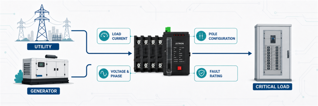
An automatic transfer switch must carry the highest current that can pass through it from either source. Calculate that current from the transferred load, not from the generator label alone, then select the next suitable ATS rating. Before ordering, also confirm voltage, phase, poles, neutral switching, short-circuit withstand, transition method, controller functions, and the applicable standard.
A 100 kVA generator does not automatically require a 100 A transfer switch. At 400 V three-phase, 100 kVA corresponds to about 144 A. At 230 V single-phase, the same apparent power would correspond to about 435 A. The power figure stayed the same. The current did not.
That is why automatic transfer switch sizing begins with the one-line diagram and the load being transferred. The generator rating is one input. It is not the whole answer.
First Decide What the ATS Will Actually Carry
Before using a formula, draw a boundary around the load side of the ATS. This avoids the most common sizing error: calculating one part of the system while specifying the switch for another.
An ATS may transfer:
- an entire low-voltage service or main distribution board;
- a dedicated emergency or life-safety bus;
- a selected-load subpanel serving pumps, lighting, controls, refrigeration, or IT equipment;
- one machine or industrial process;
- the output of a generator, inverter, or second utility source.
Suppose a building has an 800 A main service but only a 250 A essential-load board is backed up. An ATS installed on that essential board is not automatically an 800 A device. Its continuous-current requirement follows the transferred circuit, subject to the governing design rules and protective-device arrangement.
The opposite problem also occurs. A generator may be smaller than the utility service, but the ATS remains in the normal-source path and continuously carries the selected load while utility power is available. Load shedding or an essential-load panel may be needed if the generator cannot supply everything connected downstream. The switch cannot make an undersized generator carry more load.
Build the Sizing Input Sheet Before You Calculate
Good ATS sizing starts with a short list of verified inputs. If several items are unknown, mark them as open points instead of hiding them behind a large safety factor. Oversizing the ampere frame cannot correct an unsuitable neutral arrangement, a low fault-withstand rating, or a controller that cannot communicate with the generator.
| Input | Why it matters | Where to verify it |
|---|---|---|
| Transferred load | Defines what current the ATS must carry | Load schedule, one-line diagram, measured demand |
| Normal and alternate sources | Determines source arrangement and controller sequence | One-line diagram and generator/inverter data |
| Voltage and frequency | Sets insulation, sensing, and controller requirements | Project specification and source nameplates |
| Single- or three-phase system | Changes the current formula and pole configuration | Distribution drawings |
| Power in A, kW, or kVA | Determines which calculation method is valid | Load list, generator data, equipment nameplates |
| Power factor and efficiency | Required when converting certain kW values to current | Equipment or generator data |
| Motor and transformer loads | Affects transfer sequence, inrush, and source response | Motor list and starting study |
| Available fault current | Sets the required withstand and closing performance | Short-circuit study |
| Grounding and neutral design | Determines whether a solid or switched neutral is appropriate | Grounding study and local installation rules |
| Ambient and enclosure | May affect temperature rise, derating, and product series | Site data and manufacturer instructions |
For an existing facility, measured demand can be more useful than adding every connected nameplate. A plant may have 600 kW of connected equipment but never operate all of it simultaneously. Conversely, a short measurement taken during a light production shift may understate the real maximum. Use a representative demand record, the operating schedule, and planned expansion together.
For a new facility, the load schedule should identify which loads are continuous, intermittent, mutually exclusive, or shed during generator operation. This is the point where electrical design and operational priorities meet. The ATS should serve the intended emergency system, not an imaginary condition in which every connected device runs at full load forever.
Convert the Available Project Data into Amps
Use current directly when a verified maximum design current is already available. If the project gives power in kW or kVA, convert it using the correct system voltage and phase arrangement.
When the Input Is kVA
Apparent power in kVA already includes the effect of power factor, so do not divide by power factor a second time.
Single-phase:
I = S × 1,000 / V
Three-phase:
I = S × 1,000 / (√3 × VLL)
Here, I is line current in amperes, S is apparent power in kVA, V is single-phase voltage, and VLL is three-phase line-to-line voltage.
When the Input Is kW
Real power requires a power-factor assumption. If the kW figure is mechanical output from a motor rather than electrical input, efficiency also matters.
Single-phase electrical load:
I = P × 1,000 / (V × PF)
Three-phase electrical load:
I = P × 1,000 / (√3 × VLL × PF)
For a motor specified by shaft-output kW, divide by efficiency as well. Use nameplate current where possible because it reflects the actual motor design better than a generic efficiency estimate.
| Available input | What to use | Common mistake |
|---|---|---|
| Verified load current in A | Use the design current directly | Converting it back to power and adding new assumptions |
| Generator or load rating in kVA | Use the kVA formula for the correct phase and voltage | Dividing by power factor twice |
| Electrical load in kW | Use voltage, phase, and a justified power factor | Assuming PF = 1 for a mixed commercial or industrial load |
| Motor output in kW | Prefer nameplate current; otherwise include PF and efficiency | Treating mechanical output as electrical input |
| Main breaker rating only | Check whether the ATS carries the full service or a selected-load feeder | Automatically copying the main-breaker frame onto every ATS |
Connected Load, Maximum Demand, and Source Capacity
These three values can be different, and each answers a different question.
Connected load is the sum of equipment that could be connected. It is useful for understanding the system but can overstate simultaneous current when loads operate at different times.
Maximum demand is the highest credible simultaneous load under the defined operating condition. This is often the most relevant starting point for the ATS continuous-current requirement.
Source capacity is what the utility, generator, transformer, inverter, or battery system can deliver. The alternate source may be deliberately smaller than the connected load when priority controls shed nonessential circuits.
Consider a hotel with 420 A of connected emergency-side equipment. The operating study shows that fire pumps, evacuation lighting, security, and selected elevators create a maximum transferred demand of 285 A. The generator is rated for 350 A, and the controls prevent comfort HVAC from connecting during an outage. A 400 A ATS may be a defensible starting point. Adding all 420 A without recognizing the control sequence could push the project into a larger, more expensive frame. Using only the 350 A generator rating would miss the reason the system works.
The load-management sequence must be reliable and documented. If the controls fail and all 420 A can connect, the smaller source may be overloaded even though the ATS itself can carry the current. ATS sizing and generator sizing are connected, but they are not the same calculation.
Three Worked ATS Sizing Examples
Example 1: A Single-Phase Essential-Load Panel
Consider an illustrative small commercial site with a 230 V single-phase essential-load panel. The calculated simultaneous load is 11.5 kVA.
I = 11.5 × 1,000 / 230 = 50 A
The calculated current is 50 A. The correct purchasing decision is not simply “buy a 50 A ATS.” Check the continuous loading expected by the installation rules, the available product ratings, cable and protective-device ratings, and any planned load growth. If the verified requirement exceeds 50 A after those checks, a 63 A frame may be the practical selection.
A compact JUTRION automatic transfer switch may suit this type of selected-load application, but the exact model still has to match the source voltage, pole arrangement, controller logic, and short-circuit conditions.
Example 2: A 100 kVA, 400 V Three-Phase Generator
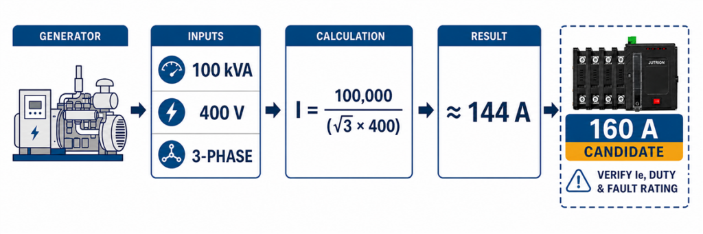
Three-phase ATS sizing calculation for a 100 kVA 400 V generator resulting in approximately 144 A.A commercial building uses a 100 kVA standby generator at 400 V, three-phase. The ATS transfers a dedicated emergency board that the generator is intended to supply.
I = 100 × 1,000 / (√3 × 400)
I ≈ 144 A
A 125 A ATS would be too small for the generator’s rated apparent-power output. The next suitable standard rating could be 160 A, provided the transferred-load calculation, operating duty, product data, and installation rules support it.
Now change one assumption. If the emergency board’s verified maximum demand is only 105 A and load management prevents additional circuits from connecting during generator operation, the engineer may size around that controlled load rather than the theoretical output of the generator. That decision must be documented in the system design. A supplier should not infer it from the generator nameplate.
This case also shows why an ATS can be rated higher than the generator. A 160 A switch connected to a source capable of 144 A is not inherently a mismatch. The switch rating is a carrying limit, not a command that forces 160 A from the generator.
Should the ATS Match the Generator or the Main Breaker?
There is no universal “match the larger nameplate” rule. Follow the current path.
If the ATS is installed at a full-service transfer point, it may carry the normal-source service load whenever the utility is available. The generator can still be smaller if the system has approved load management, but the transfer equipment and distribution architecture must suit the full normal path.
If the ATS feeds a separate essential-load board, its rating can follow that feeder’s calculated demand and design rules rather than the building’s main service rating. This is common when only critical circuits require backup power.
If the ATS is packaged with a generator for one dedicated machine, the generator current, machine demand, starting behavior, and feeder protection may all be close. Even then, verify the voltage, phase, fault current, and controller interface instead of selecting by kVA alone.
| ATS location | Primary sizing basis | Important secondary check |
|---|---|---|
| Full-service transfer | Maximum current through the service path | Service rules, generator load management, fault current |
| Essential-load subpanel | Calculated demand of selected circuits | Feeder protection and load-shedding logic |
| Dedicated machine or process | Machine operating current | Starting duty and acceptable interruption |
| Generator output switch | Generator rated current and connected transferred load | Overload protection and future parallel/source plans |
| Utility-to-utility transfer | Load current carried from either utility source | Source independence and transition permission |
A larger ATS can be used with a smaller generator when the electrical ratings and protection are coordinated. A smaller ATS cannot be justified merely because the generator is smaller if the switch carries a higher utility-side load during normal operation.
Example 3: A Motor-Heavy Industrial Emergency Bus
An industrial emergency bus has 180 A of running load, including pumps and ventilation motors. Selecting a 200 A ATS may appear sufficient. The harder question is what happens during transfer.
Motor loads can retain voltage after disconnection. If a second source is connected while the residual voltage is out of phase, the electrical and mechanical stress can exceed normal running conditions. Generator voltage and frequency may also dip when several motors restart together.
Do not solve this by applying a universal “motor load × 1.5” rule. That shortcut mixes three different decisions:
- the continuous current the ATS contacts must carry;
- the making and utilization duty of the switching equipment;
- the generator’s ability to accept starting kVA and voltage dip.
A better design may use staged restarting, load shedding, a delayed-transition neutral position, or in-phase transfer. A neutral delay can allow residual voltage from inductive loads to decay before the alternate source is connected. The chosen ATS and controller must support the required sequence.
For this project, the ampere frame cannot be finalized until the motor-starting study, transfer sequence, generator response, and upstream protection are reviewed. The honest preliminary answer is “at least the verified continuous-load requirement, then confirm the transfer duty.”
How Load Type Changes the Decision After the Amp Calculation
Two projects can have the same 250 A running current and need different transfer solutions. The difference lies in what the load does when voltage disappears and returns.
Resistive Heating and Lighting
Predominantly resistive loads usually have a straightforward relationship between power and current. The main questions are simultaneity, continuous duty, and source capacity. Some lighting systems, however, include electronic drivers with high inrush or harmonic current, so the label “lighting” is not enough.
Motors, Pumps, Compressors, and Fans
Motors create starting kVA, residual voltage, and possible phase-angle stress during transfer. The system may restart motors sequentially rather than all at once. A delayed transition can provide time for residual voltage to decay, while in-phase transfer controls can wait for a suitable phase relationship. The correct approach depends on the process and equipment.
Transformers
Transformer energization can produce a high magnetizing inrush that varies with residual flux and the point on the voltage waveform at closing. A transfer that is acceptable for steady-state transformer current may still cause a severe source voltage dip or nuisance operation of protection. Review the transformer and generator study rather than applying a generic current margin.
UPS, Data-Center, and Electronic Loads
Electronic loads can be sensitive to interruption time and source quality. They may also draw nonlinear current. A UPS can bridge an open-transition gap, but the generator and ATS controller must allow the alternate source to stabilize. Transfer thresholds that are too narrow can cause repeated switching when generator voltage or frequency hunts near the acceptance limit.
Fire Pumps and Life-Safety Loads
These systems are governed by application-specific rules and project requirements. They are not ordinary motor feeders. The current IEC 60947-6-1:2026 edition includes specific provisions for transfer switching equipment used with electric-driven fire-pump control equipment. Treat the complete approved system, controller, source, and installation rules together.
Select the Next Suitable ATS Rating, Not the Nearest Number
Once the design current is established, compare it with available product ratings. Never round down. Also avoid oversizing without a reason. A much larger ATS may increase enclosure size, cable-termination requirements, panel cost, and spare-parts burden without improving system performance.
| Calculated current | Possible next frame | What must still be checked |
|---|---|---|
| 28 A | 32 A or the next offered rating | Continuous duty, conductor and protective-device coordination |
| 50 A | 63 A where required by the verified design basis | Load growth, terminals, enclosure, pole configuration |
| 144 A | 160 A | Actual transferred load, source capacity, fault rating |
| 365 A | 400 A | Temperature, bus/cable arrangement, transfer duty |
| 1,420 A | 1,600 A | High-current switch architecture, protection, maintenance strategy |
These are illustrative mappings, not a substitute for a model-specific catalogue. JUTRION offers ATS solutions across a broad current range, but availability, class, poles, controller, and test ratings vary by series.
Check Rated Operational Current and Utilization Category
The number printed as a frame or thermal-current rating is not always the current the device can switch under every load condition. For an IEC project, verify the model’s rated operational current, Ie, at the project voltage and for the applicable utilization category.
IEC transfer switching equipment may be marked with categories such as AC-31, AC-32, or AC-33. The category reflects the type of load and switching duty used to establish the rating. Motor and mixed inductive loads can impose a more demanding making and breaking duty than predominantly resistive loads. A product that carries its full frame current in one category may have a lower Ie in another.
This changes the selection sequence. If the calculation gives 365 A, a nominal 400 A frame is only a candidate. The relevant data table must also show an Ie of at least 365 A at the system voltage and required utilization category. If it does not, move to a larger frame or a product designed for that duty.
| Result from the calculation | Preliminary frame | Next decisive check |
|---|---|---|
| 50 A at 230 V single-phase | 63 A candidate | Ie at 230 V, load duty, poles, and continuous operating condition |
| 144 A at 400 V three-phase | 160 A candidate | Ie at 400/415 V for the required utilization category |
| 365 A motor-heavy load | 400 A candidate | AC-33 duty, restart sequence, generator response, and product data |
This is the missing bridge between a power-system calculation and a real catalogue selection. The formula produces a required current. The manufacturer’s tested Ie confirms whether a particular model can perform that duty.
Check Temperature, Enclosure, Terminals, and Installation Duty
Catalogue current is tied to stated conditions. A switch installed in a cool, ventilated electrical room does not experience the same thermal environment as a sealed outdoor cabinet exposed to sun, dust, salt, or high ambient temperature.
Confirm the permitted ambient range and any manufacturer derating. Do not assume that choosing the next frame automatically guarantees full current at an elevated temperature. Enclosure construction, ventilation, busbar arrangement, cable size, number of conductors per terminal, and internal heat from adjacent equipment all affect the final assembly.
Kapasitas terminal perlu mendapat perhatian sejak awal pada proyek arus tinggi. ATS 1.600 A mungkin memerlukan beberapa kabel paralel atau sambungan bus per fasa. Panel builder memerlukan rentang konduktor yang disetujui, susunan lug, ruang pembengkokan, arah masuk kabel, nilai torsi, dan kapasitas netral. Sakelar yang memadai secara elektrik tetapi tidak dapat menerima kabel yang ditentukan bukanlah pilihan yang dapat digunakan.
Frekuensi pengoperasian juga penting. ATS yang hanya digunakan selama pemadaman utilitas sesekali memiliki profil pengoperasian yang berbeda dari lokasi terpencil generator-ke-generator yang mengganti sumber sesuai jadwal. Data ketahanan mekanis dan elektrik, akses pemeliharaan, suku cadang, dan persyaratan bypass menjadi lebih penting seiring meningkatnya frekuensi transfer dan biaya waktu henti.
Peringkat Ampere Hanyalah Gerbang Pertama
Arus yang dihitung dengan benar tetap dapat mengarah pada pemilihan ATS yang salah. Selesaikan pemeriksaan berikut sebelum menerbitkan spesifikasi pembelian.
Cocokkan Kedua Sumber untuk Tegangan, Fasa, dan Frekuensi
ATS dan kontrolernya harus sesuai untuk sumber normal, sumber alternatif, dan beban. Konfirmasikan tegangan nominal, rentang penginderaan yang diizinkan, susunan fasa tunggal atau tiga fasa, urutan fasa, dan frekuensi. Untuk sumber generator, konfirmasikan bahwa kontroler tidak melakukan transfer hingga tegangan dan frekuensi stabil.
Tentukan Apakah Netral Harus Disakelar
ATS tiga fasa tiga kutub menyakelar konduktor fasa dan biasanya membiarkan netral tetap terhubung. ATS empat kutub menyakelar netral sebagai kutub dengan peringkat penuh. Susunan netral yang disakelar umumnya dipertimbangkan dengan sumber yang diturunkan secara terpisah, tetapi “gunakan 4P untuk setiap generator” bukanlah aturan universal yang aman.
Keputusan ini bergantung pada desain pentanahan dan pengikatan, susunan sumber, proteksi arus sisa, peraturan setempat, dan bagaimana jalur arus netral berperilaku dalam operasi normal dan darurat. Minta perancang sistem untuk mengonfirmasi poin ini. Hal ini tidak dapat diselesaikan dengan rumus ampere.
Pilih Kelas Peralatan Transfer dan Arsitektur Proteksi
Sakelar transfer kelas PC pada dasarnya adalah perangkat transfer. Umumnya mengandalkan proteksi arus lebih hulu yang terkoordinasi. Susunan kelas CB menggunakan perangkat sakelar berbasis pemutus sirkuit dan dapat mengintegrasikan fungsi pemutusan beban lebih dan hubung singkat, tergantung pada rakitan yang diuji.
Jangan memilih kelas hanya dari kecepatan atau harga. Tanyakan siapa yang bertanggung jawab untuk memutus gangguan hilir, perangkat proteksi mana yang berada di hulu, dan apakah kombinasi lengkap memiliki peringkat yang diperlukan. Rentang MCCB dan panduan sistem ACB arus tinggi JUTRION memberikan konteks yang berguna untuk sisi protektif dari keputusan tersebut.
Periksa Peringkat Hubung Singkat IEC atau WCR UL
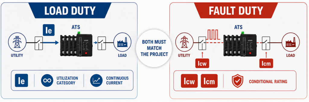
Comparison of ATS rated operational current Ie with short-circuit ratings Icw, Icm, and conditional rating.Peringkat arus 400 A memberi tahu Anda berapa banyak arus beban yang dapat dibawa ATS dalam kondisi terukurnya. Ini tidak memberi tahu Anda bahwa sakelar dapat bertahan dari gangguan 50 kA di titik pemasangannya.
Untuk proyek IEC, tinjau nilai hubung singkat yang ditandai untuk peralatan sakelar transfer. Tergantung pada produk dan susunan proteksi, ini dapat mencakup arus tahan hubung singkat terukur Icw, kapasitas pembuatan hubung singkat terukur Icm, atau peringkat hubung singkat bersyarat yang terkait dengan perangkat proteksi hulu yang ditentukan. Nilai waktu dan kondisi proteksi sama pentingnya dengan nilai arus.
Untuk aplikasi Amerika Utara, peringkat ketahanan dan penutupan WCR harus memadai untuk arus gangguan yang tersedia di lokasi ATS sesuai kondisi yang ditandai. WCR dapat bergantung pada sekering atau pemutus sirkuit tertentu dan waktu pemutusannya.
Pada sistem mana pun, gunakan informasi koordinasi spesifik model. Kapasitas pemutusan yang tercetak pada MCCB hulu tidak dapat sekadar disalin ke dalam spesifikasi ATS; kedua perangkat menjalankan tugas yang berbeda selama gangguan.
Pilih Metode Transisi di Sekitar Beban
Transisi terbuka adalah break-before-make: sumber pertama terputus sebelum sumber kedua terhubung. Transisi tertunda menambahkan interval mati yang disengaja. Transisi tertutup secara singkat memparalelkan sumber yang dapat diterima dan memperkenalkan kontrol tambahan serta persyaratan utilitas.
Sebagian besar aplikasi tidak memilih metode transisi berdasarkan peringkat arus. Mereka memilihnya berdasarkan perilaku beban, toleransi interupsi, tegangan sisa, respons generator, dan aturan paralel sumber.
Tentukan Kontroler dan Antarmuka Proyek
Sistem utilitas-ke-generator biasanya membutuhkan lebih dari sekadar penginderaan tegangan. Periksa kontak start dan stop generator, tunda start, pengaturan sumber tersedia, tunda transfer, tunda transfer balik, waktu pendinginan, operasi manual, fungsi uji, kontak alarm, dan indikasi jarak jauh.
Proyek industri dan daya kritis mungkin juga memerlukan komunikasi RS485/Modbus, pencatatan kejadian, pelepasan beban, antarmuka sistem kebakaran, atau pengaturan bypass-isolasi. Fitur-fitur ini dapat mengubah seri dan selungkup bahkan ketika peringkat ampere tetap sama.
Gunakan Proses Penentuan Ukuran Sakelar Transfer Otomatis Sembilan Langkah Ini
- Tandai batas ATS pada diagram satu garis. Identifikasi setiap sirkuit yang tetap berada di hilir dalam operasi normal dan darurat.
- Tetapkan permintaan transfer maksimum yang kredibel. Gunakan data terukur atau jadwal beban yang terdokumentasi, bukan penjumlahan yang tidak dijelaskan atau potret beban ringan.
- Konversikan daya ke arus dengan benar. Bedakan ampere, kW, dan kVA; gunakan rumus satu fasa atau tiga fasa yang benar.
- Periksa sumber alternatif. Konfirmasikan bahwa generator, inverter, atau sumber utilitas kedua dapat memasok beban yang dimaksud dan urutan penyalaan.
- Pilih peringkat arus yang sesuai berikutnya. Gunakan dasar desain yang terverifikasi dan rangka produk yang tersedia. Jangan pernah membulatkan ke bawah.
- Tinjau perilaku beban selama transfer. Tangani tegangan sisa motor, arus masuk transformator, ride-through UPS, pelepasan beban, dan urutan mulai ulang.
- Lengkapi konfigurasi listrik. Tentukan tegangan, frekuensi, kutub, perlakuan netral, arsitektur PC/CB, dan metode transisi.
- Verifikasi koordinasi gangguan dan proteksi. Bandingkan kinerja tahan/tutup yang ditandai dengan arus gangguan yang tersedia dan perangkat proteksi hulu.
- Selesaikan spesifikasi proyek. Tambahkan fungsi pengontrol, komunikasi, selungkup, terminal, kondisi sekitar, standar yang berlaku, kuantitas, dan pasar tujuan.
Urutan ini sengaja memisahkan perhitungan dari verifikasi. Ini memungkinkan pembeli memperoleh ukuran awal yang cepat tanpa berpura-pura bahwa hasil itu sendiri mengizinkan pemasangan.
Simpan catatan perhitungan bersama dengan penawaran. Minimal, catat sumber data beban, tanggal atau kondisi operasi yang diwakili oleh pengukuran apa pun, asumsi keberagaman, rumus yang digunakan, dan alasan memilih rangka akhir. Jika revisi proyek kemudian menambah pompa, mengubah tegangan generator, atau memindahkan ATS ke titik berbeda pada diagram satu garis, tim dapat segera melihat apakah hasil awal masih valid. Tanpa catatan itu, ukuran rangka sering bertahan melalui beberapa revisi gambar bahkan setelah asumsi di baliknya telah berubah.
IEC 60947-6-1:2026 dan UL 1008 Bukan Label yang Dapat Dipertukarkan
Edisi IEC saat ini adalah IEC 60947-6-1:2026. Ini berlaku untuk peralatan sakelar transfer yang digunakan untuk memindahkan beban antara sumber daya hingga 1.000 V AC atau 1.500 V DC. Edisi 2026 mencakup peralatan yang dioperasikan secara manual, jarak jauh, dan otomatis serta menambahkan perlakuan khusus untuk area termasuk peralatan bypass/isolasi, ATSE transisi tertutup, pengontrol ATS mandiri, dan peralatan sakelar transfer pompa kebakaran.
Untuk proyek Amerika Utara, UL Solutions mengidentifikasi UL 1008 sebagai standar yang digunakan untuk sakelar transfer otomatis dalam sistem darurat dan siaga opsional, serta sakelar transfer non-otomatis. Persyaratan pemasangan juga bergantung pada kode listrik yang berlaku, klasifikasi proyek, dan otoritas yang memiliki yurisdiksi.
Perhitungan ampere berguna di pasar mana pun. Ini tidak membuktikan bahwa ATS tertentu tersertifikasi, terdaftar, atau disetujui untuk proyek itu. Konfirmasikan model, standar, tegangan, peringkat hubung singkat, dan kondisi pemasangan yang tepat sebelum memesan.
Mengapa Dua Unit ATS dengan Peringkat Amp yang Sama Mungkin Tidak Setara
Peringkat ampere hanyalah satu baris pada papan nama. Dua sakelar transfer 400 A dapat membawa arus beban normal yang sama sambil menggunakan mekanisme sakelar, pengaturan netral, arsitektur proteksi, pengontrol, dan peringkat hubung singkat yang berbeda.
Lima pemeriksaan mengungkap sebagian besar perbedaan yang berarti:
- Arsitektur transfer: Perangkat kelas PC biasanya bergantung pada proteksi hulu yang terkoordinasi, sementara desain kelas CB menggunakan sakelar berbasis pemutus sirkuit dan dapat mencakup fungsi arus lebih.
- Jumlah kutub: Unit tiga kutub biasanya mempertahankan netral padat. Unit empat kutub menyakelar netral dan harus sesuai dengan desain pentanahan.
- Kinerja gangguan: Kemampuan tahan hubung singkat dan penutupan yang ditandai harus sesuai dengan arus gangguan yang tersedia dan perangkat proteksi hulu yang ditentukan.
- Fungsi pengontrol: Penginderaan sumber, kontak generator, penundaan yang dapat disesuaikan, catatan peristiwa, komunikasi, dan fungsi kontrol beban sangat bervariasi.
- Bukti yang berlaku: Tegangan, tugas pemanfaatan, kondisi sekitar, persyaratan IEC atau UL, dan dokumentasi pengujian khusus model harus sesuai dengan proyek.
Ini adalah perbedaan sistem, bukan tambahan opsional penjualan. ATS kelas PC dasar mungkin merupakan jawaban yang tepat untuk panel distribusi terkoordinasi. Fasilitas kritis mungkin memerlukan transisi tertunda, pemantauan lanjutan, atau isolasi bypass. Tidak ada produk yang secara otomatis lebih baik karena memiliki lebih banyak fungsi. Perangkat yang benar adalah yang konfigurasi terujinya cocok dengan diagram satu garis dan urutan operasi.
Catat Hasilnya sebagai Spesifikasi Awal Lengkap
Setelah perhitungan, tuliskan asumsi dan pemeriksaan yang tersisa. Spesifikasi awal harus mengidentifikasi beban yang dipindahkan, arus terhitung, kerangka yang diusulkan, tegangan, fase, frekuensi, susunan sumber, kutub, metode transisi, arsitektur proteksi, antarmuka pengontrol, lingkungan pemasangan, dan standar yang berlaku.
Catatan ini membuat tinjauan rekayasa lebih mudah dan mencegah ukuran kerangka terpisah dari asumsi di baliknya. Ini juga menciptakan serah terima yang bersih antara perancang sistem, pembuat panel, pemasok generator, dan produsen ATS.
Setelah masukan tersebut dikonfirmasi, bandingkan dengan konfigurasi yang tersedia di rangkaian sakelar transfer otomatis JUTRION. Pemilihan model akhir harus didasarkan pada peringkat spesifik model dan kondisi proyek, bukan hanya pada arus.
Urutan praktisnya sederhana: tentukan apa yang akan dibawa ATS, hitung arusnya, verifikasi Ie untuk kategori pemanfaatan aktual, lalu selesaikan pemeriksaan kutub, transisi, pengontrol, dan hubung singkat.
