

Quick Answer: What Size Automatic Transfer Switch Do You Need?
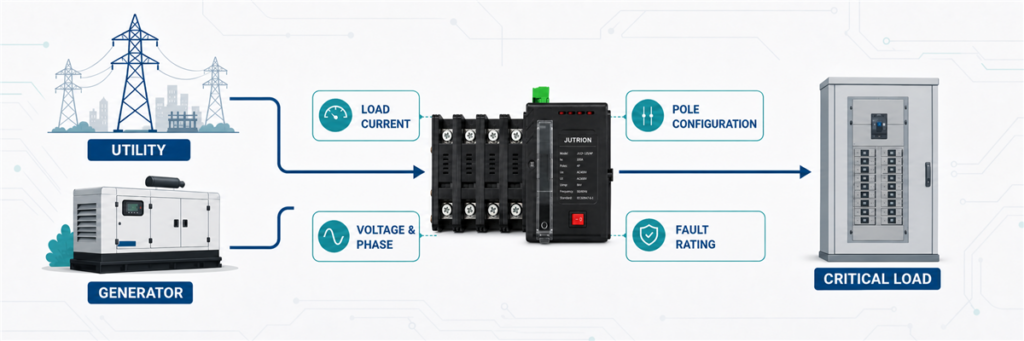
An automatic transfer switch must carry the highest current that can pass through it from either source. Calculate that current from the transferred load, not from the generator label alone, then select the next suitable ATS rating. Before ordering, also confirm voltage, phase, poles, neutral switching, short-circuit withstand, transition method, controller functions, and the applicable standard.
A 100 kVA generator does not automatically require a 100 A transfer switch. At 400 V three-phase, 100 kVA corresponds to about 144 A. At 230 V single-phase, the same apparent power would correspond to about 435 A. The power figure stayed the same. The current did not.
That is why automatic transfer switch sizing begins with the one-line diagram and the load being transferred. The generator rating is one input. It is not the whole answer.
First Decide What the ATS Will Actually Carry
Before using a formula, draw a boundary around the load side of the ATS. This avoids the most common sizing error: calculating one part of the system while specifying the switch for another.
An ATS may transfer:
- an entire low-voltage service or main distribution board;
- a dedicated emergency or life-safety bus;
- a selected-load subpanel serving pumps, lighting, controls, refrigeration, or IT equipment;
- one machine or industrial process;
- the output of a generator, inverter, or second utility source.
Suppose a building has an 800 A main service but only a 250 A essential-load board is backed up. An ATS installed on that essential board is not automatically an 800 A device. Its continuous-current requirement follows the transferred circuit, subject to the governing design rules and protective-device arrangement.
The opposite problem also occurs. A generator may be smaller than the utility service, but the ATS remains in the normal-source path and continuously carries the selected load while utility power is available. Load shedding or an essential-load panel may be needed if the generator cannot supply everything connected downstream. The switch cannot make an undersized generator carry more load.
Build the Sizing Input Sheet Before You Calculate
Good ATS sizing starts with a short list of verified inputs. If several items are unknown, mark them as open points instead of hiding them behind a large safety factor. Oversizing the ampere frame cannot correct an unsuitable neutral arrangement, a low fault-withstand rating, or a controller that cannot communicate with the generator.
| Input | 重要な理由 | Where to verify it |
|---|---|---|
| Transferred load | Defines what current the ATS must carry | Load schedule, one-line diagram, measured demand |
| Normal and alternate sources | Determines source arrangement and controller sequence | One-line diagram and generator/inverter data |
| Voltage and frequency | Sets insulation, sensing, and controller requirements | Project specification and source nameplates |
| Single- or three-phase system | Changes the current formula and pole configuration | Distribution drawings |
| Power in A, kW, or kVA | Determines which calculation method is valid | Load list, generator data, equipment nameplates |
| Power factor and efficiency | Required when converting certain kW values to current | Equipment or generator data |
| Motor and transformer loads | Affects transfer sequence, inrush, and source response | Motor list and starting study |
| Available fault current | Sets the required withstand and closing performance | Short-circuit study |
| Grounding and neutral design | Determines whether a solid or switched neutral is appropriate | Grounding study and local installation rules |
| Ambient and enclosure | May affect temperature rise, derating, and product series | Site data and manufacturer instructions |
For an existing facility, measured demand can be more useful than adding every connected nameplate. A plant may have 600 kW of connected equipment but never operate all of it simultaneously. Conversely, a short measurement taken during a light production shift may understate the real maximum. Use a representative demand record, the operating schedule, and planned expansion together.
For a new facility, the load schedule should identify which loads are continuous, intermittent, mutually exclusive, or shed during generator operation. This is the point where electrical design and operational priorities meet. The ATS should serve the intended emergency system, not an imaginary condition in which every connected device runs at full load forever.
Convert the Available Project Data into Amps
Use current directly when a verified maximum design current is already available. If the project gives power in kW or kVA, convert it using the correct system voltage and phase arrangement.
When the Input Is kVA
Apparent power in kVA already includes the effect of power factor, so do not divide by power factor a second time.
Single-phase:
I = S × 1,000 / V
Three-phase:
I = S × 1,000 / (√3 × VLL)
Here, I is line current in amperes, S is apparent power in kVA, V is single-phase voltage, and VLL is three-phase line-to-line voltage.
When the Input Is kW
Real power requires a power-factor assumption. If the kW figure is mechanical output from a motor rather than electrical input, efficiency also matters.
Single-phase electrical load:
I = P × 1,000 / (V × PF)
Three-phase electrical load:
I = P × 1,000 / (√3 × VLL × PF)
For a motor specified by shaft-output kW, divide by efficiency as well. Use nameplate current where possible because it reflects the actual motor design better than a generic efficiency estimate.
| Available input | What to use | Common mistake |
|---|---|---|
| Verified load current in A | Use the design current directly | Converting it back to power and adding new assumptions |
| Generator or load rating in kVA | Use the kVA formula for the correct phase and voltage | Dividing by power factor twice |
| Electrical load in kW | Use voltage, phase, and a justified power factor | Assuming PF = 1 for a mixed commercial or industrial load |
| Motor output in kW | Prefer nameplate current; otherwise include PF and efficiency | Treating mechanical output as electrical input |
| Main breaker rating only | Check whether the ATS carries the full service or a selected-load feeder | Automatically copying the main-breaker frame onto every ATS |
Connected Load, Maximum Demand, and Source Capacity
These three values can be different, and each answers a different question.
Connected load is the sum of equipment that could be connected. It is useful for understanding the system but can overstate simultaneous current when loads operate at different times.
Maximum demand is the highest credible simultaneous load under the defined operating condition. This is often the most relevant starting point for the ATS continuous-current requirement.
Source capacity is what the utility, generator, transformer, inverter, or battery system can deliver. The alternate source may be deliberately smaller than the connected load when priority controls shed nonessential circuits.
Consider a hotel with 420 A of connected emergency-side equipment. The operating study shows that fire pumps, evacuation lighting, security, and selected elevators create a maximum transferred demand of 285 A. The generator is rated for 350 A, and the controls prevent comfort HVAC from connecting during an outage. A 400 A ATS may be a defensible starting point. Adding all 420 A without recognizing the control sequence could push the project into a larger, more expensive frame. Using only the 350 A generator rating would miss the reason the system works.
The load-management sequence must be reliable and documented. If the controls fail and all 420 A can connect, the smaller source may be overloaded even though the ATS itself can carry the current. ATS sizing and generator sizing are connected, but they are not the same calculation.
Three Worked ATS Sizing Examples
Example 1: A Single-Phase Essential-Load Panel
Consider an illustrative small commercial site with a 230 V single-phase essential-load panel. The calculated simultaneous load is 11.5 kVA.
I = 11.5 × 1,000 / 230 = 50 A
The calculated current is 50 A. The correct purchasing decision is not simply “buy a 50 A ATS.” Check the continuous loading expected by the installation rules, the available product ratings, cable and protective-device ratings, and any planned load growth. If the verified requirement exceeds 50 A after those checks, a 63 A frame may be the practical selection.
A compact JUTRION automatic transfer switch may suit this type of selected-load application, but the exact model still has to match the source voltage, pole arrangement, controller logic, and short-circuit conditions.
Example 2: A 100 kVA, 400 V Three-Phase Generator
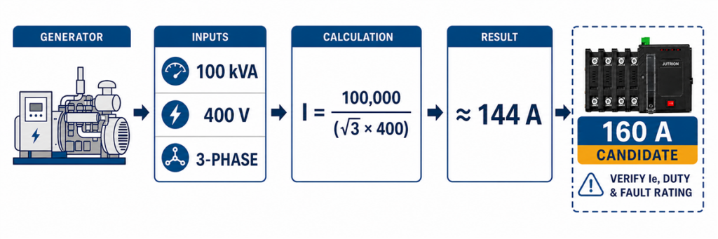
Three-phase ATS sizing calculation for a 100 kVA 400 V generator resulting in approximately 144 A.A commercial building uses a 100 kVA standby generator at 400 V, three-phase. The ATS transfers a dedicated emergency board that the generator is intended to supply.
I = 100 × 1,000 / (√3 × 400)
I ≈ 144 A
A 125 A ATS would be too small for the generator’s rated apparent-power output. The next suitable standard rating could be 160 A, provided the transferred-load calculation, operating duty, product data, and installation rules support it.
Now change one assumption. If the emergency board’s verified maximum demand is only 105 A and load management prevents additional circuits from connecting during generator operation, the engineer may size around that controlled load rather than the theoretical output of the generator. That decision must be documented in the system design. A supplier should not infer it from the generator nameplate.
This case also shows why an ATS can be rated higher than the generator. A 160 A switch connected to a source capable of 144 A is not inherently a mismatch. The switch rating is a carrying limit, not a command that forces 160 A from the generator.
Should the ATS Match the Generator or the Main Breaker?
There is no universal “match the larger nameplate” rule. Follow the current path.
If the ATS is installed at a full-service transfer point, it may carry the normal-source service load whenever the utility is available. The generator can still be smaller if the system has approved load management, but the transfer equipment and distribution architecture must suit the full normal path.
If the ATS feeds a separate essential-load board, its rating can follow that feeder’s calculated demand and design rules rather than the building’s main service rating. This is common when only critical circuits require backup power.
If the ATS is packaged with a generator for one dedicated machine, the generator current, machine demand, starting behavior, and feeder protection may all be close. Even then, verify the voltage, phase, fault current, and controller interface instead of selecting by kVA alone.
| ATS location | Primary sizing basis | Important secondary check |
|---|---|---|
| Full-service transfer | Maximum current through the service path | Service rules, generator load management, fault current |
| Essential-load subpanel | Calculated demand of selected circuits | Feeder protection and load-shedding logic |
| Dedicated machine or process | Machine operating current | Starting duty and acceptable interruption |
| Generator output switch | Generator rated current and connected transferred load | Overload protection and future parallel/source plans |
| Utility-to-utility transfer | Load current carried from either utility source | Source independence and transition permission |
A larger ATS can be used with a smaller generator when the electrical ratings and protection are coordinated. A smaller ATS cannot be justified merely because the generator is smaller if the switch carries a higher utility-side load during normal operation.
Example 3: A Motor-Heavy Industrial Emergency Bus
An industrial emergency bus has 180 A of running load, including pumps and ventilation motors. Selecting a 200 A ATS may appear sufficient. The harder question is what happens during transfer.
Motor loads can retain voltage after disconnection. If a second source is connected while the residual voltage is out of phase, the electrical and mechanical stress can exceed normal running conditions. Generator voltage and frequency may also dip when several motors restart together.
Do not solve this by applying a universal “motor load × 1.5” rule. That shortcut mixes three different decisions:
- the continuous current the ATS contacts must carry;
- the making and utilization duty of the switching equipment;
- the generator’s ability to accept starting kVA and voltage dip.
A better design may use staged restarting, load shedding, a delayed-transition neutral position, or in-phase transfer. A neutral delay can allow residual voltage from inductive loads to decay before the alternate source is connected. The chosen ATS and controller must support the required sequence.
For this project, the ampere frame cannot be finalized until the motor-starting study, transfer sequence, generator response, and upstream protection are reviewed. The honest preliminary answer is “at least the verified continuous-load requirement, then confirm the transfer duty.”
How Load Type Changes the Decision After the Amp Calculation
Two projects can have the same 250 A running current and need different transfer solutions. The difference lies in what the load does when voltage disappears and returns.
Resistive Heating and Lighting
Predominantly resistive loads usually have a straightforward relationship between power and current. The main questions are simultaneity, continuous duty, and source capacity. Some lighting systems, however, include electronic drivers with high inrush or harmonic current, so the label “lighting” is not enough.
Motors, Pumps, Compressors, and Fans
Motors create starting kVA, residual voltage, and possible phase-angle stress during transfer. The system may restart motors sequentially rather than all at once. A delayed transition can provide time for residual voltage to decay, while in-phase transfer controls can wait for a suitable phase relationship. The correct approach depends on the process and equipment.
Transformers
Transformer energization can produce a high magnetizing inrush that varies with residual flux and the point on the voltage waveform at closing. A transfer that is acceptable for steady-state transformer current may still cause a severe source voltage dip or nuisance operation of protection. Review the transformer and generator study rather than applying a generic current margin.
UPS, Data-Center, and Electronic Loads
Electronic loads can be sensitive to interruption time and source quality. They may also draw nonlinear current. A UPS can bridge an open-transition gap, but the generator and ATS controller must allow the alternate source to stabilize. Transfer thresholds that are too narrow can cause repeated switching when generator voltage or frequency hunts near the acceptance limit.
Fire Pumps and Life-Safety Loads
These systems are governed by application-specific rules and project requirements. They are not ordinary motor feeders. The current IEC 60947-6-1:2026 edition includes specific provisions for transfer switching equipment used with electric-driven fire-pump control equipment. Treat the complete approved system, controller, source, and installation rules together.
Select the Next Suitable ATS Rating, Not the Nearest Number
Once the design current is established, compare it with available product ratings. Never round down. Also avoid oversizing without a reason. A much larger ATS may increase enclosure size, cable-termination requirements, panel cost, and spare-parts burden without improving system performance.
| Calculated current | Possible next frame | What must still be checked |
|---|---|---|
| 28 A | 32 A or the next offered rating | Continuous duty, conductor and protective-device coordination |
| 50 A | 63 A where required by the verified design basis | Load growth, terminals, enclosure, pole configuration |
| 144 A | 160 A | Actual transferred load, source capacity, fault rating |
| 365 A | 400 A | Temperature, bus/cable arrangement, transfer duty |
| 1,420 A | 1,600 A | High-current switch architecture, protection, maintenance strategy |
These are illustrative mappings, not a substitute for a model-specific catalogue. JUTRION offers ATS solutions across a broad current range, but availability, class, poles, controller, and test ratings vary by series.
Check Rated Operational Current and Utilization Category
The number printed as a frame or thermal-current rating is not always the current the device can switch under every load condition. For an IEC project, verify the model’s rated operational current, Ie, at the project voltage and for the applicable utilization category.
IEC transfer switching equipment may be marked with categories such as AC-31, AC-32, or AC-33. The category reflects the type of load and switching duty used to establish the rating. Motor and mixed inductive loads can impose a more demanding making and breaking duty than predominantly resistive loads. A product that carries its full frame current in one category may have a lower Ie in another.
This changes the selection sequence. If the calculation gives 365 A, a nominal 400 A frame is only a candidate. The relevant data table must also show an Ie of at least 365 A at the system voltage and required utilization category. If it does not, move to a larger frame or a product designed for that duty.
| Result from the calculation | Preliminary frame | Next decisive check |
|---|---|---|
| 50 A at 230 V single-phase | 63 A candidate | Ie at 230 V, load duty, poles, and continuous operating condition |
| 144 A at 400 V three-phase | 160 A candidate | Ie at 400/415 V for the required utilization category |
| 365 A motor-heavy load | 400 A candidate | AC-33 使用区分、再始動シーケンス、発電機応答、および製品データ |
これは電力系統計算と実際のカタログ選定との間の欠けている橋渡しです。計算式は必要な電流を算出します。メーカーの試験済み Ie が、特定のモデルがその使用区分を実行できるかどうかを確認します。.
温度、筐体、端子、および設置使用区分を確認する
カタログ電流は明記された条件に紐付いています。涼しく換気された電気室に設置された開閉器は、日光、塵埃、塩分、または高い周囲温度にさらされる密閉型屋外キャビネットと同じ熱環境には置かれません。.
許容周囲温度範囲とメーカーの定格低減を確認してください。単に次のフレームを選ぶことで高温時に全電流が自動的に保証されるとは考えないでください。筐体構造、換気、ブスバー配置、ケーブルサイズ、端子あたりの導体数、隣接機器からの内部発熱はすべて最終的なアセンブリに影響します。.
大電流プロジェクトでは端子容量に早い段階で注意を払う必要があります。1,600 A の ATS では、相ごとに複数の並列ケーブルまたはブス接続が必要になる場合があります。盤製作者は承認された導体範囲、ラグ配置、曲げスペース、引込方向、トルク値、および中性線容量を必要とします。指定されたケーブルを受け入れられない電気的に適切な開閉器は、使用可能な選定とは言えません。.
動作頻度も重要です。まれな商用電源停電時にのみ使用される ATS は、スケジュールに従って電源を交互に切り替える発電機対発電機の遠隔サイトとは異なる動作プロファイルを持ちます。切替頻度と停止コストが増加するにつれて、機械的および電気的耐久性データ、保守アクセス、予備部品、バイパス要件がより重要になります。.
アンペア定格は最初の関門に過ぎない
正しく計算された電流でも、誤った ATS 選定につながる可能性があります。購入仕様書を発行する前に、以下の確認を完了してください。.
両方の電源の電圧、相、および周波数を一致させる
ATS とそのコントローラは、常用電源、予備電源、および負荷に適合している必要があります。公称電圧、許容検出範囲、単相または三相構成、相順、および周波数を確認してください。発電機電源の場合、電圧と周波数が安定するまでコントローラが切替を行わないことを確認してください。.
中性線を開閉するかどうかを決定する
三相3極 ATS は相導体を開閉し、通常は中性線を非開閉のまま残します。4極 ATS は中性線を全定格極として開閉します。中性線開閉構成は一般的に別電源方式で検討されますが、「すべての発電機に4Pを使用する」ことは安全な普遍的ルールではありません。.
この決定は、接地およびボンディング設計、電源構成、残留電流保護、地域規則、および通常運転時と非常運転時の中性線電流経路の挙動によって決まります。この点はシステム設計者に確認してもらってください。アンペア計算式だけでは解決できません。.
切替機器クラスと保護アーキテクチャを選択する
PCクラス切替開閉器は主に切替装置です。一般的に、協調の取れた上流の過電流保護に依存します。CBクラス構成は回路遮断器ベースの開閉装置を使用し、試験済みアセンブリに応じて過負荷および短絡遮断機能を統合する場合があります。.
速度や価格だけでクラスを選択しないでください。下流故障を遮断する責任者が誰か、上流の保護装置が何か、そして完全な組み合わせが必要な定格を満たしているかどうかを確認してください。JUTRION の MCCB 製品群 および大電流 ACBシステムガイド は、その判断の保護側面に有用な背景情報を提供します。.
IEC短絡定格またはUL WCRを確認する
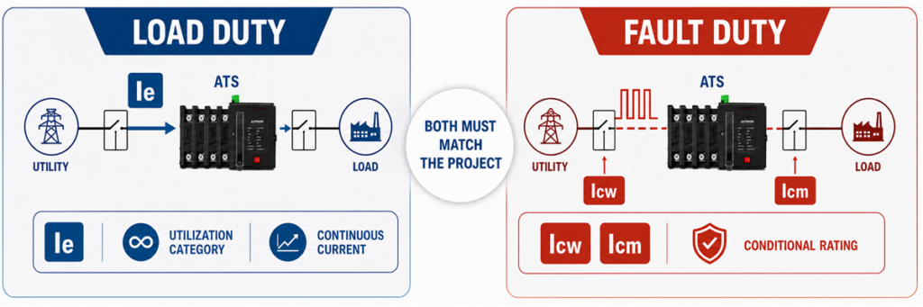
Comparison of ATS rated operational current Ie with short-circuit ratings Icw, Icm, and conditional rating.400 Aの電流定格は、ATSが定格条件下でどれだけの負荷電流を流せるかを示します。設置箇所で50 kAの故障に耐えられることを示すものではありません。.
IECプロジェクトでは、切替開閉装置に表示された短絡値を確認してください。製品と保護構成によっては、定格短時間耐電流 Icw, 、定格短絡投入容量 Icm, 、または指定された上流側保護装置に関連付けられた条件付き短絡定格が含まれます。時間値と保護条件は、電流値と同じくらい重要です。.
北米向け用途では、耐量および投入定格 WCR が、表示条件下でATS設置箇所の利用可能故障電流に対して十分でなければなりません。WCRは特定のヒューズまたは遮断器とその遮断時間に依存する場合があります。.
どちらのシステムでも、モデル固有の協調情報を使用してください。上流側MCCBに表示された遮断容量をそのままATS仕様に転記することはできません。故障時に2つの装置は異なる役割を果たします。.
負荷に応じて切替方式を選択する
開放切替はブレーク・ビフォア・メイクです。第1電源が遮断されてから第2電源が投入されます。遅延切替は意図的な無電圧時間を追加します。閉路切替は許容される電源を短時間並列し、追加の制御と電力会社の要件が発生します。.
ほとんどの用途では、電流定格で切替方式を選択しません。負荷挙動、停電許容時間、残留電圧、発電機応答、電源並列規則に基づいて選択します。.
コントローラとプロジェクトインターフェースを指定する
商用-発電機システムでは通常、電圧検出だけでは不十分です。発電機の起動・停止接点、起動遅延、電源確立設定、切替遅延、再切替遅延、クールダウン時間、手動操作、試験機能、警報接点、遠隔表示を確認してください。.
産業用および重要電力プロジェクトでは、RS485/Modbus通信、イベントログ、負荷遮断、火災システムインターフェース、またはバイパス・アイソレーション構成も必要になる場合があります。これらの機能は、アンペア定格が同じでもシリーズや筐体を変更することがあります。.
この9ステップの自動切替スイッチ選定プロセスを使用する
- 単線結線図上でATSの境界を明示します。. 通常運転時および非常運転時に下流側に残るすべての回路を特定します。.
- 最大の信頼できる切替需要を確定します。. 説明のない合計や軽負荷時のスナップショットではなく、実測データまたは文書化された負荷表を使用します。.
- 電力を電流に正しく変換します。. アンペア、kW、kVAを区別し、正しい単相または三相の式を使用します。.
- 予備電源を確認します。. 発電機、インバータ、または第2商用電源が意図した負荷と起動シーケンスを供給できることを確認します。.
- 次に適切な電流定格を選択します。. 検証された設計基準と利用可能な製品フレームを使用します。決して切り下げないでください。.
- 切替時の負荷挙動を確認します。. モータ残留電圧、変圧器励磁突入電流、UPS ライドスルー、負荷遮断、再起動順序に対処します。.
- 電気的構成を完了します。. 電圧、周波数、極数、中性点処理、PC/CB アーキテクチャ、切替方式を指定します。.
- 故障・保護協調を検証します。. 表示された耐量/投入性能を、利用可能な故障電流および上流側保護装置と比較します。.
- プロジェクト仕様を仕上げます。. コントローラ機能、通信、筐体、端子、周囲条件、適用規格、数量、出荷先市場を追加します。.
この手順は、計算と検証を意図的に分離しています。これにより、購入者は結果だけで設置が承認されるかのように装うことなく、迅速な概算サイズを取得できます。.
計算記録を見積書とともに保管してください。最低限、負荷データの出所、測定値が表す日付または運転条件、多様性の仮定、使用した計算式、最終フレームを選定した理由を記録します。後でプロジェクト改訂によりポンプが追加されたり、発電機電圧が変更されたり、ATS が単線結線図上の別の位置に移動されたりした場合、チームは元の結果が依然として有効かどうかを即座に確認できます。その記録がなければ、フレームサイズは、その背後にある仮定が変更された後も、何度かの図面改訂を経て存続することがよくあります。.
IEC 60947-6-1:2026 と UL 1008 は互換性のあるラベルではありません
現在の IEC 版は IEC 60947-6-1:2026. です。これは、1,000 V AC または 1,500 V DC までの電源間で負荷を切り替えるために使用される切替開閉装置に適用されます。2026 年版は、手動、遠隔、自動操作の機器を対象とし、バイパス/絶縁機器、閉路切替 ATSE、スタンドアロン ATS コントローラ、消火ポンプ切替開閉装置などの分野に対する特定の扱いを追加しています。.
北米プロジェクトの場合、, UL Solutions は UL 1008 を、非常用および予備電源システムにおける自動切替スイッチ、ならびに非自動切替スイッチに使用される規格として特定しています。設置要件は、適用される電気工事規程、プロジェクト分類、および管轄当局によっても異なります。.
アンペア計算はどちらの市場でも有用です。それは特定の ATS がそのプロジェクトに対して認証、リスト、または承認されていることを証明するものではありません。発注前に、正確なモデル、規格、電圧、短絡定格、および設置条件を確認してください。.
同じアンペア定格の 2 台の ATS が同等とは限らない理由
アンペア定格は銘板上の 1 行にすぎません。2 台の 400 A 切替スイッチは、同じ通常負荷電流を流しながらも、異なる切替機構、中性点配置、保護アーキテクチャ、コントローラ、短絡定格を使用している場合があります。.
5 つのチェックで、意味のある違いのほとんどが明らかになります。
- 切替アーキテクチャ: PC クラスの機器は通常、協調された上流側保護に依存しますが、CB クラスの設計は回路遮断器ベースの切替を使用し、過電流機能を含む場合があります。.
- 極数: 3 極ユニットは通常、非接地中性点を維持します。4 極ユニットは中性点を切り替えるため、接地設計に適合している必要があります。.
- 故障性能: 表示された短絡耐量および投入能力は、利用可能な故障電流および指定された上流側保護装置と一致している必要があります。.
- コントローラ機能: 電源検出、発電機接点、調整可能な遅延、イベント記録、通信、負荷制御機能は大きく異なります。.
- 適用可能な証拠: 電圧、使用負荷、周囲条件、IECまたはUL要件、およびモデル固有の試験文書がプロジェクトに適合している必要があります。.
これらはシステム上の相違であり、任意の販売オプションではありません。基本的なPCクラスATSは、協調配電盤にとって正しい答えとなる場合があります。重要施設では、遅延切替、高度な監視、またはバイパス絶縁が必要になる場合があります。機能が多いからといって、どちらの製品も自動的に優れているわけではありません。正しい装置とは、試験済みの構成が単線結線図および動作シーケンスと一致するものです。.
結果を完全な予備仕様として記録する
計算後、前提条件と残りの確認事項を書き留めます。予備仕様では、切替負荷、計算電流、提案フレーム、電圧、相、周波数、電源構成、極数、切替方式、保護アーキテクチャ、コントローラインターフェース、設置環境、および適用規格を特定する必要があります。.
この記録により、エンジニアリングレビューが容易になり、フレームサイズがその背後にある前提条件から切り離されるのを防ぎます。また、システム設計者、盤製作者、発電機供給者、およびATS製造者の間の明確な引き継ぎも実現します。.
これらの入力が確認されたら、それらを JUTRION automatic transfer switch range. の利用可能な構成と比較します。最終的なモデル選定は、電流だけでなく、モデル固有の定格とプロジェクト条件に基づいて行う必要があります。.
実用的な順序はシンプルです。ATSが負担するものを定義し、電流を計算し、実際の使用カテゴリに対するIeを確認し、その後、極数、切替、コントローラ、および短絡の確認を完了します。.
