

Mabilis na Sagot: Anong Laki ng Automatic Transfer Switch ang Kailangan Mo?
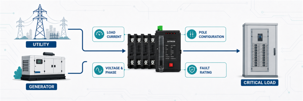
Ang isang automatic transfer switch ay dapat magdala ng pinakamataas na current na maaaring dumaan dito mula sa alinmang source. Kalkulahin ang current na iyon mula sa transferred load, hindi mula sa generator label lamang, pagkatapos ay piliin ang susunod na angkop na ATS rating. Bago mag-order, kumpirmahin din ang voltage, phase, poles, neutral switching, short-circuit withstand, transition method, controller functions, at ang applicable standard.
Ang isang 100 kVA generator ay hindi awtomatikong nangangailangan ng 100 A transfer switch. Sa 400 V three-phase, ang 100 kVA ay katumbas ng humigit-kumulang 144 A. Sa 230 V single-phase, ang parehong apparent power ay katumbas ng humigit-kumulang 435 A. Ang power figure ay nanatiling pareho. Ang current ay hindi.
Iyon ang dahilan kung bakit ang automatic transfer switch sizing ay nagsisimula sa one-line diagram at sa load na inililipat. Ang generator rating ay isang input. Hindi ito ang buong sagot.
Magpasya Muna Kung Ano ang Talagang Dadalhin ng ATS
Bago gumamit ng formula, gumuhit ng boundary sa paligid ng load side ng ATS. Iniiwasan nito ang pinakakaraniwang sizing error: ang pagkalkula ng isang bahagi ng system habang tinutukoy ang switch para sa iba.
Ang isang ATS ay maaaring maglipat ng:
- isang buong low-voltage service o main distribution board;
- isang dedicated emergency o life-safety bus;
- isang selected-load subpanel na nagsisilbi sa mga pumps, lighting, controls, refrigeration, o IT equipment;
- isang machine o industrial process;
- ang output ng isang generator, inverter, o pangalawang utility source.
Ipagpalagay na ang isang gusali ay may 800 A main service ngunit isang 250 A essential-load board lamang ang naka-back up. Ang isang ATS na naka-install sa essential board na iyon ay hindi awtomatikong isang 800 A device. Ang continuous-current requirement nito ay sumusunod sa transferred circuit, alinsunod sa mga governing design rules at protective-device arrangement.
Ang kabaligtaran na problema ay nangyayari rin. Ang isang generator ay maaaring mas maliit kaysa sa utility service, ngunit ang ATS ay nananatili sa normal-source path at patuloy na nagdadala ng selected load habang available ang utility power. Maaaring kailanganin ang load shedding o isang essential-load panel kung hindi kayang i-supply ng generator ang lahat ng nakakonekta sa downstream. Hindi kayang gawin ng switch na magdala ng mas maraming load ang isang undersized generator.
Buuin ang Sizing Input Sheet Bago Ka Magkalkula
Ang mahusay na ATS sizing ay nagsisimula sa isang maikling listahan ng mga na-verify na input. Kung ang ilang mga item ay hindi alam, markahan ang mga ito bilang open points sa halip na itago ang mga ito sa likod ng isang malaking safety factor. Hindi kayang itama ng oversizing sa ampere frame ang isang hindi angkop na neutral arrangement, isang mababang fault-withstand rating, o isang controller na hindi makakapag-communicate sa generator.
| Input | Bakit ito mahalaga | Kung saan ito i-verify |
|---|---|---|
| Nailipat na karga | Tinutukoy kung anong current ang dapat dalhin ng ATS | Iskedyul ng karga, isang-linyang dayagram, nasukat na demand |
| Normal at alternate sources | Tinutukoy ang source arrangement at controller sequence | One-line diagram at generator/inverter data |
| Voltage at frequency | Nagtatakda ng insulation, sensing, at controller requirements | Project specification at source nameplates |
| Single- o three-phase system | Binabago ang current formula at pole configuration | Mga guhit ng distribusyon |
| Power sa A, kW, o kVA | Tinutukoy kung aling paraan ng pagkalkula ang valid | Listahan ng karga, datos ng generator, mga nameplate ng kagamitan |
| Power factor at efficiency | Kinakailangan kapag nagko-convert ng ilang kW values sa current | Equipment o generator data |
| Motor at transformer loads | Nakakaapekto sa pagkakasunod-sunod ng paglipat, inrush, at tugon ng pinagmumulan | Listahan ng motor at pag-aaral ng pagsisimula |
| Magagamit na fault current | Itinatakda ang kinakailangang withstand at closing performance | Pag-aaral ng short-circuit |
| Disenyo ng grounding at neutral | Tinutukoy kung ang solid o switched neutral ay angkop | Pag-aaral ng grounding at mga lokal na tuntunin sa pag-install |
| Ambient at enclosure | Maaaring makaapekto sa pagtaas ng temperatura, derating, at serye ng produkto | Data ng site at mga tagubilin ng manufacturer |
Para sa isang umiiral na pasilidad, ang nasusukat na demand ay maaaring mas kapaki-pakinabang kaysa sa pagdaragdag ng bawat nakakonektang nameplate. Maaaring may 600 kW ng nakakonektang kagamitan ang isang planta ngunit hindi kailanman pinapatakbo ang lahat ng ito nang sabay-sabay. Sa kabaligtaran, ang isang maikling pagsukat na kinuha sa panahon ng magaang production shift ay maaaring maliitin ang tunay na maximum. Gumamit ng representative na talaan ng demand, ang iskedyul ng operasyon, at ang nakaplanong pagpapalawak nang magkakasama.
Para sa isang bagong pasilidad, dapat tukuyin ng load schedule kung aling mga load ang tuloy-tuloy, paulit-ulit, mutually exclusive, o isinasara sa panahon ng operasyon ng generator. Ito ang punto kung saan nagtatagpo ang disenyo ng elektrikal at mga priyoridad sa operasyon. Dapat pagsilbihan ng ATS ang nilalayong emergency system, hindi isang imaginary na kondisyon kung saan ang bawat nakakonektang aparato ay tumatakbo sa buong load magpakailanman.
I-convert ang Available Project Data sa Amps
Direktang gamitin ang current kapag mayroon nang verified na maximum design current. Kung ang proyekto ay nagbibigay ng power sa kW o kVA, i-convert ito gamit ang tamang system voltage at phase arrangement.
Kapag ang Input ay kVA
Ang apparent power sa kVA ay kasama na ang epekto ng power factor, kaya huwag itong hatiin sa power factor sa pangalawang pagkakataon.
Single-phase:
I = S × 1,000 / V
Three-phase:
I = S × 1,000 / (√3 × VLL)
Here, I is line current in amperes, S ay apparent power sa kVA, V ay single-phase voltage, at VLL ay three-phase line-to-line voltage.
Kapag ang Input ay kW
Ang real power ay nangangailangan ng power-factor assumption. Kung ang kW figure ay mechanical output mula sa isang motor sa halip na electrical input, mahalaga rin ang efficiency.
Single-phase electrical load:
I = P × 1,000 / (V × PF)
Three-phase electrical load:
I = P × 1,000 / (√3 × VLL × PF)
Para sa isang motor na tinukoy ng shaft-output kW, hatiin din sa efficiency. Gumamit ng nameplate current kung posible dahil mas tumpak nitong ipinapakita ang aktwal na disenyo ng motor kaysa sa isang generic na pagtatantya ng efficiency.
| Available na input | Ano ang gagamitin | Karaniwang pagkakamali |
|---|---|---|
| Na-verify na load current sa A | Direktang gamitin ang design current | Ang pag-convert nito pabalik sa power at pagdaragdag ng mga bagong assumption |
| Generator o load rating sa kVA | Gamitin ang kVA formula para sa tamang phase at voltage | Ang paghahati sa power factor nang dalawang beses |
| Electrical load sa kW | Gumamit ng voltage, phase, at isang makatwirang power factor | Ang pag-aakalang PF = 1 para sa isang mixed commercial o industrial load |
| Motor output sa kW | Mas mainam ang nameplate current; kung hindi, isama ang PF at efficiency | Ang pagtrato sa mechanical output bilang electrical input |
| Main breaker rating lamang | Suriin kung ang ATS ay nagdadala ng buong serbisyo o isang selected-load feeder | Ang awtomatikong pagkopya ng main-breaker frame sa bawat ATS |
Connected Load, Maximum Demand, at Source Capacity
Ang tatlong halagang ito ay maaaring magkaiba, at bawat isa ay sumasagot sa iba't ibang tanong.
Ang connected load ay ang kabuuan ng kagamitan na maaaring ikonekta. Kapaki-pakinabang ito para sa pag-unawa sa system ngunit maaaring mag-overstate ng simultaneous current kapag ang mga load ay gumagana sa magkakaibang oras.
Ang maximum demand ay ang pinakamataas na kapani-paniwalang simultaneous load sa ilalim ng tinukoy na kondisyon ng operasyon. Ito ang kadalasang pinaka-kaugnay na panimulang punto para sa ATS continuous-current requirement.
Ang source capacity ay kung ano ang kayang ibigay ng utility, generator, transformer, inverter, o battery system. Ang alternate source ay maaaring sadyang mas maliit kaysa sa connected load kapag isinasara ng mga priority control ang mga hindi mahalagang circuit.
Isaalang-alang ang isang hotel na may 420 A ng nakakonektang kagamitan sa emergency-side. Ipinapakita ng operating study na ang mga fire pump, evacuation lighting, security, at mga piling elevator ay lumilikha ng maximum transferred demand na 285 A. Ang generator ay may rating na 350 A, at pinipigilan ng mga kontrol ang comfort HVAC na kumonekta sa panahon ng outage. Ang isang 400 A ATS ay maaaring maging isang maipagtatanggol na panimulang punto. Ang pagdaragdag ng lahat ng 420 A nang hindi kinikilala ang control sequence ay maaaring magtulak sa proyekto sa isang mas malaki at mas mahal na frame. Ang paggamit lamang ng 350 A generator rating ay makalilimot sa dahilan kung bakit gumagana ang sistema.
Ang load-management sequence ay dapat na maaasahan at nakadokumento. Kung mabigo ang mga kontrol at lahat ng 420 A ay maaaring kumonekta, ang mas maliit na source ay maaaring ma-overload kahit na kaya ng ATS mismo na dalhin ang current. Ang ATS sizing at generator sizing ay magkaugnay, ngunit hindi sila parehong kalkulasyon.
Tatlong Worked ATS Sizing Examples
Halimbawa 1: Isang Single-Phase na Panel ng Essential-Load
Isaalang-alang ang isang halimbawang maliit na komersyal na site na may 230 V single-phase na panel ng essential-load. Ang kalkuladong sabay-sabay na load ay 11.5 kVA.
I = 11.5 × 1,000 / 230 = 50 A
Ang kalkuladong current ay 50 A. Ang tamang desisyon sa pagbili ay hindi simpleng “bumili ng 50 A ATS.” Suriin ang tuloy-tuloy na loading na inaasahan ng mga panuntunan sa pag-install, ang mga available na rating ng produkto, mga rating ng cable at protective-device, at anumang nakaplanong paglaki ng load. Kung ang napatunayang kinakailangan ay lumampas sa 50 A pagkatapos ng mga pagsusuring iyon, maaaring ang 63 A frame ang praktikal na pagpili.
Isang compact na Awtomatikong switch ng paglilipat ng JUTRION ay maaaring angkop sa ganitong uri ng selected-load na aplikasyon, ngunit ang eksaktong modelo ay kailangan pa ring tumugma sa source voltage, pole arrangement, controller logic, at short-circuit conditions.
Halimbawa 2: Isang 100 kVA, 400 V Three-Phase na Generator
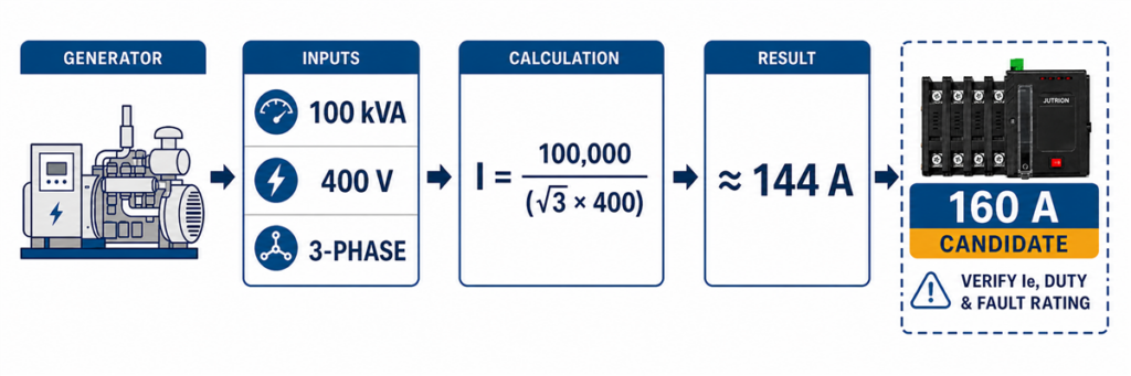
Pagkalkula ng laki ng three-phase ATS para sa isang 100 kVA 400 V generator na nagreresulta sa humigit-kumulang 144 A.Ang isang komersyal na gusali ay gumagamit ng 100 kVA standby generator sa 400 V, three-phase. Inililipat ng ATS ang isang dedikadong emergency board na nilalayong suplayan ng generator.
I = 100 × 1,000 / (√3 × 400)
I ≈ 144 A
Ang 125 A ATS ay magiging napakaliit para sa rated apparent-power output ng generator. Ang susunod na angkop na standard rating ay maaaring 160 A, kung sinusuportahan ito ng transferred-load calculation, operating duty, product data, at installation rules.
Ngayon baguhin ang isang assumption. Kung ang verified maximum demand ng emergency board ay 105 A lamang at pinipigilan ng load management ang mga karagdagang circuit na kumonekta habang tumatakbo ang generator, maaaring sukatin ng engineer ang paligid ng controlled load na iyon sa halip na ang theoretical output ng generator. Ang desisyong iyon ay dapat idokumento sa system design. Hindi dapat ipagpalagay ito ng supplier mula sa generator nameplate.
Ipinapakita rin ng kasong ito kung bakit maaaring mas mataas ang rating ng isang ATS kaysa sa generator. Ang isang 160 A switch na konektado sa isang source na may kakayahang 144 A ay hindi likas na mismatch. Ang rating ng switch ay isang limitasyon sa pagdadala, hindi isang utos na pilitin ang 160 A mula sa generator.
Dapat bang Tumugma ang ATS sa Generator o sa Main Breaker?
Walang pangkalahatang panuntunang “itugma ang mas malaking nameplate.” Sundin ang daanan ng current.
Kung ang ATS ay naka-install sa isang full-service transfer point, maaari nitong dalhin ang normal-source service load tuwing available ang utility. Maaari pa ring mas maliit ang generator kung may aprubadong load management ang system, ngunit ang transfer equipment at distribution architecture ay dapat na angkop sa buong normal na daanan.
Kung ang ATS ay nagpapakain ng hiwalay na essential-load board, maaaring sundin ng rating nito ang calculated demand at design rules ng feeder na iyon sa halip na ang main service rating ng gusali. Karaniwan ito kapag ang mga kritikal na circuit lamang ang nangangailangan ng backup power.
Kung ang ATS ay naka-package kasama ng isang generator para sa isang dedikadong makina, maaaring magkalapit lahat ang generator current, demand ng makina, starting behavior, at feeder protection. Kahit gayon, i-verify ang voltage, phase, fault current, at controller interface sa halip na pumili batay sa kVA lamang.
| Lokasyon ng ATS | Pangunahing batayan ng pagsusukat | Mahalagang pangalawang pagsusuri |
|---|---|---|
| Buong-serbisyong paglilipat | Pinakamataas na current sa daanan ng service | Mga panuntunan sa service, load management ng generator, fault current |
| Subpanel ng mahahalagang karga | Kalkuladong demand ng mga napiling circuit | Proteksyon ng feeder at load-shedding logic |
| Dedikadong makina o proseso | Operating current ng makina | Starting duty at katanggap-tanggap na interruption |
| Switch ng output ng generator | Rated current ng generator at konektadong transferred load | Proteksyon sa overload at mga plano sa hinaharap na parallel/source |
| Paglilipat mula utility patungong utility | Load current na dinadala mula sa alinmang utility source | Kalayaan ng source at pahintulot sa transition |
Maaaring gumamit ng mas malaking ATS kasama ang mas maliit na generator kapag pinag-ugnay ang mga electrical rating at proteksyon. Hindi maaaring bigyang-katwiran ang mas maliit na ATS dahil lamang mas maliit ang generator kung ang switch ay nagdadala ng mas mataas na load sa panig ng utility sa normal na operasyon.
Halimbawa 3: Isang Motor-Heavy Industrial Emergency Bus
Ang isang industrial emergency bus ay may 180 A na running load, kabilang ang mga pump at ventilation motor. Ang pagpili ng 200 A ATS ay maaaring mukhang sapat. Ang mas mahirap na tanong ay kung ano ang mangyayari sa panahon ng paglipat.
Maaaring mapanatili ng mga motor load ang boltahe pagkatapos madiskonekta. Kung ang pangalawang source ay ikinonekta habang ang residual voltage ay wala sa phase, ang electrical at mechanical stress ay maaaring lumampas sa normal na kondisyon ng pagtakbo. Ang boltahe at frequency ng generator ay maaari ring bumaba kapag sabay-sabay na nag-restart ang ilang motor.
Huwag lutasin ito sa pamamagitan ng paglalapat ng pangkalahatang tuntuning “motor load × 1.5”. Pinaghahalo ng shortcut na iyon ang tatlong magkakaibang desisyon:
- ang tuluy-tuloy na current na dapat dalhin ng mga contact ng ATS;
- ang making at utilization duty ng switching equipment;
- ang kakayahan ng generator na tanggapin ang starting kVA at voltage dip.
Ang mas mahusay na disenyo ay maaaring gumamit ng staged restarting, load shedding, delayed-transition neutral position, o in-phase transfer. Ang neutral delay ay maaaring magpahintulot sa residual voltage mula sa mga inductive load na bumaba bago ikonekta ang alternate source. Dapat suportahan ng napiling ATS at controller ang kinakailangang sequence.
Para sa proyektong ito, hindi pa maaaring tapusin ang ampere frame hanggang sa masuri ang motor-starting study, transfer sequence, generator response, at upstream protection. Ang tapat na paunang sagot ay “hindi bababa sa na-verify na continuous-load requirement, pagkatapos ay kumpirmahin ang transfer duty.”
Paano Binabago ng Uri ng Load ang Desisyon Pagkatapos ng Amp Calculation
Maaaring magkapareho ang dalawang proyekto ng 250 A running current at nangangailangan ng magkaibang solusyon sa paglipat. Ang pagkakaiba ay nasa kung ano ang ginagawa ng load kapag nawala at bumabalik ang boltahe.
Resistive Heating at Lighting
Ang mga predominantly resistive load ay karaniwang may direktang ugnayan sa pagitan ng power at current. Ang mga pangunahing tanong ay simultaneity, continuous duty, at source capacity. Gayunpaman, ang ilang lighting system ay may kasamang electronic driver na may mataas na inrush o harmonic current, kaya hindi sapat ang label na “lighting”.
Motors, Pumps, Compressors, at Fans
Ang mga motor ay lumilikha ng starting kVA, residual voltage, at posibleng phase-angle stress habang naglilipat. Maaaring i-restart ng system ang mga motor nang sunud-sunod sa halip na sabay-sabay. Ang delayed transition ay maaaring magbigay ng oras para mawala ang residual voltage, habang ang in-phase transfer controls ay maaaring maghintay para sa angkop na phase relationship. Ang tamang approach ay nakasalalay sa proseso at kagamitan.
Mga transpormer
Ang transformer energization ay maaaring magdulot ng mataas na magnetizing inrush na nag-iiba ayon sa residual flux at sa punto sa voltage waveform sa pagsasara. Ang transfer na katanggap-tanggap para sa steady-state transformer current ay maaari pa ring magdulot ng matinding source voltage dip o nuisance operation ng protection. Suriin ang transformer at generator study sa halip na maglapat ng generic current margin.
UPS, Data-Center, at Electronic Loads
Ang mga electronic load ay maaaring sensitibo sa interruption time at source quality. Maaari rin silang kumonsumo ng nonlinear current. Maaaring tulayin ng UPS ang open-transition gap, ngunit dapat pahintulutan ng generator at ATS controller na maging stable ang alternate source. Ang mga transfer threshold na masyadong makitid ay maaaring magdulot ng paulit-ulit na switching kapag ang generator voltage o frequency ay naghahanap malapit sa acceptance limit.
Fire Pumps at Life-Safety Loads
Ang mga sistemang ito ay pinamamahalaan ng mga application-specific na panuntunan at mga kinakailangan ng proyekto. Hindi sila ordinaryong motor feeder. Ang kasalukuyang IEC 60947-6-1:2026 na edisyon ay may kasamang mga tiyak na probisyon para sa transfer switching equipment na ginagamit sa electric-driven fire-pump control equipment. Ituring nang magkakasama ang kumpletong approved system, controller, source, at installation rules.
Piliin ang Susunod na Angkop na ATS Rating, Hindi ang Pinakamalapit na Numero
Kapag naitatag na ang design current, ihambing ito sa mga available na product rating. Huwag kailanman mag-round down. Iwasan din ang oversizing nang walang dahilan. Ang mas malaking ATS ay maaaring magpataas ng enclosure size, cable-termination requirements, panel cost, at spare-parts burden nang hindi nagpapabuti sa system performance.
| Kinakalkulang kuryente | Posibleng susunod na frame | Ano pa ang dapat suriin |
|---|---|---|
| 28 A | 32 A o ang susunod na inaalok na rating | Continuous duty, conductor at protective-device coordination |
| 50 A | 63 A kung kinakailangan ng verified design basis | Paglaki ng karga, mga terminal, enclosure, konpigurasyon ng poste |
| 144 A | 160 A | Aktwal na inilipat na load, kapasidad ng source, fault rating |
| 365 A | 400 A | Temperatura, bus/cable arrangement, transfer duty |
| 1,420 A | 1,600 A | High-current switch architecture, proteksyon, diskarte sa maintenance |
Ito ay mga ilustratibong mapping, hindi kapalit ng katalogong partikular sa modelo. Nag-aalok ang JUTRION ng mga ATS solution sa malawak na hanay ng current, ngunit ang availability, class, poles, controller, at test ratings ay nag-iiba ayon sa serye.
Suriin ang Rated Operational Current at Utilization Category
Ang numerong nakalimbag bilang frame o thermal-current rating ay hindi palaging ang current na kayang i-switch ng device sa bawat kondisyon ng load. Para sa isang IEC project, beripikahin ang rated operational current ng modelo, Ibig sabihin, sa project voltage at para sa naaangkop na utilization category.
Ang IEC transfer switching equipment ay maaaring markahan ng mga kategorya tulad ng AC-31, AC-32, o AC-33. Ang kategorya ay sumasalamin sa uri ng load at switching duty na ginamit upang itatag ang rating. Ang motor at mixed inductive loads ay maaaring magpataw ng mas demanding na making at breaking duty kaysa sa predominantly resistive loads. Ang isang produkto na nagtataglay ng buong frame current nito sa isang kategorya ay maaaring may mas mababang Ie sa iba.
Binabago nito ang sequence ng pagpili. Kung ang kalkulasyon ay nagbibigay ng 365 A, ang nominal na 400 A frame ay kandidato lamang. Ang nauugnay na data table ay dapat ding magpakita ng Ie na hindi bababa sa 365 A sa system voltage at kinakailangang utilization category. Kung hindi, lumipat sa mas malaking frame o sa produktong dinisenyo para sa duty na iyon.
| Resulta mula sa kalkulasyon | Paunang frame | Susunod na mapagpasyang pagsusuri |
|---|---|---|
| 50 A sa 230 V single-phase | 63 A na kandidato | Ie sa 230 V, load duty, poles, at tuloy-tuloy na kondisyon ng operasyon |
| 144 A sa 400 V three-phase | 160 A na kandidato | Ie sa 400/415 V para sa kinakailangang utilization category |
| 365 A motor-mabigat na karga | 400 A na kandidato | AC-33 duty, restart sequence, generator response, and product data |
This is the missing bridge between a power-system calculation and a real catalogue selection. The formula produces a required current. The manufacturer’s tested Ie confirms whether a particular model can perform that duty.
Check Temperature, Enclosure, Terminals, and Installation Duty
Catalogue current is tied to stated conditions. A switch installed in a cool, ventilated electrical room does not experience the same thermal environment as a sealed outdoor cabinet exposed to sun, dust, salt, or high ambient temperature.
Confirm the permitted ambient range and any manufacturer derating. Do not assume that choosing the next frame automatically guarantees full current at an elevated temperature. Enclosure construction, ventilation, busbar arrangement, cable size, number of conductors per terminal, and internal heat from adjacent equipment all affect the final assembly.
Terminal capacity deserves early attention on high-current projects. A 1,600 A ATS may require multiple parallel cables or bus connections per phase. The panel builder needs the approved conductor range, lug arrangement, bending space, entry direction, torque values, and neutral capacity. An electrically adequate switch that cannot accept the specified cables is not a usable selection.
Frequency of operation also matters. An ATS used only during occasional utility outages has a different operating profile from a generator-to-generator remote site that alternates sources on a schedule. Mechanical and electrical endurance data, maintenance access, spare parts, and bypass requirements become more important as transfer frequency and the cost of downtime increase.
Ampere Rating Is Only the First Gate
A correctly calculated current can still lead to the wrong ATS. Complete the following checks before issuing a purchase specification.
1. Match Both Sources for Voltage, Phase, and Frequency
The ATS and its controller must be suitable for the normal source, alternate source, and load. Confirm nominal voltage, allowable sensing range, single-phase or three-phase arrangement, phase sequence, and frequency. For a generator source, confirm the controller does not transfer until voltage and frequency are stable.
2. Decide Whether the Neutral Must Be Switched
A three-phase, three-pole ATS switches the phase conductors and normally leaves a solid neutral. A four-pole ATS switches the neutral as a fully rated pole. Switched-neutral arrangements are commonly considered with separately derived sources, but “use 4P for every generator” is not a safe universal rule.
The decision depends on the grounding and bonding design, source arrangement, residual-current protection, local rules, and how neutral current paths behave in normal and emergency operation. Have the system designer confirm this point. It cannot be settled by the ampere formula.
3. Choose the Transfer Equipment Class and Protection Architecture
A PC-class transfer switch is primarily a transfer device. It generally relies on coordinated upstream overcurrent protection. A CB-class arrangement uses circuit-breaker-based switching devices and may integrate overload and short-circuit interruption functions, depending on the tested assembly.
Do not select the class from speed or price alone. Ask who is responsible for clearing a downstream fault, which protective device is upstream, and whether the complete combination has the required ratings. JUTRION’s MCCB range and high-current ACB system guide provide useful context for the protective side of that decision.
4. Check IEC Short-Circuit Ratings or UL WCR
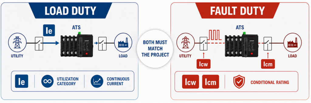
Paghahambing ng ATS rated operational current Ie sa mga short-circuit rating na Icw, Icm, at conditional rating.A 400 A current rating tells you how much load current the ATS can carry under its rated conditions. It does not tell you that the switch can survive a 50 kA fault at its installation point.
For an IEC project, review the short-circuit values marked for the transfer switching equipment. Depending on the product and protection arrangement, these can include rated short-time withstand current Icw, rated short-circuit making capacity Icm, or a conditional short-circuit rating tied to a specified upstream protective device. The time value and protection conditions matter as much as the current value.
For a North American application, the withstand and closing rating WCR must be adequate for the available fault current at the ATS location under its marked conditions. A WCR can depend on a particular fuse or circuit breaker and its clearing time.
In either system, use the model-specific coordination information. The breaking capacity printed on an upstream MCCB cannot simply be copied into the ATS specification; the two devices perform different jobs during a fault.
5. Select the Transition Method Around the Load
Open transition is break-before-make: the first source disconnects before the second connects. Delayed transition adds an intentional off interval. Closed transition briefly parallels acceptable sources and introduces additional controls and utility requirements.
Most applications do not choose a transition method by current rating. They choose it by load behavior, interruption tolerance, residual voltage, generator response, and source-paralleling rules.
6. Specify the Controller and Project Interfaces
A utility-to-generator system normally needs more than voltage sensing. Check generator start and stop contacts, start delay, source-available settings, transfer delay, retransfer delay, cool-down time, manual operation, test functions, alarm contacts, and remote indication.
Industrial and critical-power projects may also need RS485/Modbus communication, event logging, load shedding, fire-system interfaces, or a bypass-isolation arrangement. These features can change the series and enclosure even when the ampere rating stays the same.
Use This Nine-Step Automatic Transfer Switch Sizing Process
- Mark the ATS boundary on the one-line diagram. Identify every circuit that remains downstream in normal and emergency operation.
- Establish the maximum credible transferred demand. Use measured data or a documented load schedule, not an unexplained sum or a light-load snapshot.
- Convert power to current correctly. Distinguish amperes, kW, and kVA; use the correct single- or three-phase formula.
- Check the alternate source. Confirm that the generator, inverter, or second utility source can supply the intended load and starting sequence.
- Select the next suitable current rating. Use the verified design basis and available product frames. Never round down.
- Review load behavior during transfer. Address motor residual voltage, transformer inrush, UPS ride-through, load shedding, and restart order.
- Complete the electrical configuration. Specify voltage, frequency, poles, neutral treatment, PC/CB architecture, and transition method.
- Verify fault and protection coordination. Compare the marked withstand/closing performance with available fault current and the upstream protective device.
- Finish the project specification. Add controller functions, communications, enclosure, terminals, ambient conditions, applicable standard, quantity, and destination market.
This sequence intentionally separates calculation from verification. It lets a buyer obtain a fast preliminary size without pretending that the result alone authorizes installation.
Keep the calculation record with the quotation. At minimum, record the source of the load data, the date or operating condition represented by any measurements, the diversity assumptions, the formula used, and the reason for choosing the final frame. If a later project revision adds a pump, changes the generator voltage, or moves the ATS to a different point on the one-line diagram, the team can see immediately whether the original result is still valid. Without that record, a frame size often survives through several drawing revisions even after the assumptions behind it have changed.
IEC 60947-6-1:2026 and UL 1008 Are Not Interchangeable Labels
The current IEC edition is IEC 60947-6-1:2026. It applies to transfer switching equipment used to transfer loads between power sources up to 1,000 V AC or 1,500 V DC. The 2026 edition covers manually, remotely, and automatically operated equipment and adds specific treatment for areas including bypass/isolation equipment, closed-transition ATSE, standalone ATS controllers, and fire-pump transfer switching equipment.
For North American projects, UL Solutions identifies UL 1008 as the standard used for automatic transfer switches in emergency and optional standby systems, as well as nonautomatic transfer switches. Installation requirements also depend on the applicable electrical code, project classification, and authority having jurisdiction.
An ampere calculation is useful in either market. It does not prove that a specific ATS is certified, listed, or approved for that project. Confirm the exact model, standard, voltage, short-circuit rating, and installation conditions before ordering.
Why Two ATS Units with the Same Amp Rating May Not Be Equivalent
The ampere rating is only one line on the nameplate. Two 400 A transfer switches may carry the same normal load current while using different switching mechanisms, neutral arrangements, protection architectures, controllers, and short-circuit ratings.
Five checks reveal most of the meaningful differences:
- Transfer architecture: A PC-class device normally depends on coordinated upstream protection, while a CB-class design uses circuit-breaker-based switching and may include overcurrent functions.
- Number of poles: A three-pole unit normally retains a solid neutral. A four-pole unit switches the neutral and must suit the grounding design.
- Fault performance: The marked short-circuit withstand and closing capability must match the available fault current and the specified upstream protective device.
- Controller functions: Source sensing, generator contacts, adjustable delays, event records, communication, and load-control functions vary widely.
- Applicable evidence: Voltage, utilization duty, ambient conditions, IEC or UL requirements, and model-specific test documentation must match the project.
These are system differences, not optional sales extras. A basic PC-class ATS may be the correct answer for a coordinated distribution panel. A critical facility may need delayed transition, advanced monitoring, or bypass isolation. Neither product is automatically better because it has more functions. The correct device is the one whose tested configuration matches the one-line diagram and operating sequence.
Record the Result as a Complete Preliminary Specification
After the calculation, write down the assumptions and the remaining checks. A preliminary specification should identify the transferred load, calculated current, proposed frame, voltage, phase, frequency, source arrangement, poles, transition method, protection architecture, controller interfaces, installation environment, and applicable standard.
This record makes the engineering review easier and prevents a frame size from being separated from the assumptions behind it. It also creates a clean handoff between the system designer, panel builder, generator supplier, and ATS manufacturer.
Once those inputs are confirmed, compare them with the available configurations in the JUTRION automatic transfer switch range. Final model selection should be based on the model-specific ratings and project conditions, not on current alone.
The practical order is simple: define what the ATS will carry, calculate the current, verify Ie for the actual utilization category, and then complete the pole, transition, controller, and short-circuit checks.
