

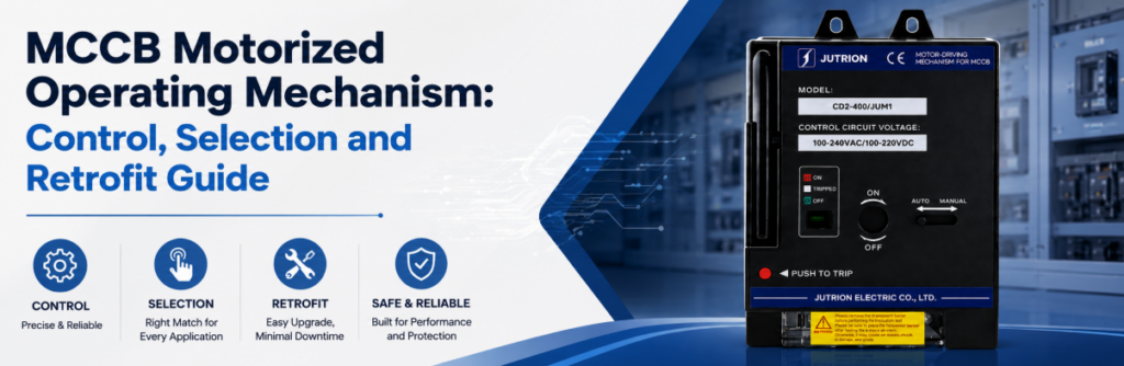
MCCB電動操作機構の制御、選定および後付けガイドクイックアンサー:MCCBモータオペレータの役割とは?
RCCBは MCCB電動操作機構, (MCCBモータオペレータとも呼ばれる)は、指令に応じて互換性のある配線用遮断器を機械的状態間で動かす電気アクチュエータです。遮断器と適合する機構によって、遮断器の開放、投入、およびトリップ後のリセットが可能です。遠隔で遮断器を 投入 できる唯一の遮断器付属装置です。一方、シャントトリップと不足電圧引き外し装置は開放しかできません。.
制御室からフィーダ遮断器にCLOSE指令を送っても何も起きない場合、まずモータ故障が疑われがちです。しかしモータは正常であることが多く、遮断器がまだTRIPPED状態にある、セレクタがMANUALになっている、投入許可条件が欠けている、または操作中に制御電源が低下している可能性があります。.
これが本ガイドの核心です。モータオペレータはハンドルを回す電動の手ではありません。自動化システムが指令を出し、許可ロジックが実行可否を判断し、機構が遮断器を動かし、補助接点が結果を確認するという連鎖の一環です。どのリンクでも仕様が未確定であれば、「MCCBの遠隔操作」は完全な機能とは言えません。.
モータオペレータは保護装置でもありません。電流を検知せず、故障でトリップせず、遮断器のIcu を上げることも、トリップユニットを変更することもありません。また、コンタクタの代わりにもなりません。モータオペレータ付き遮断器は頻繁な操作向けではなく、モータ回路が要求する1日数千回のサイクル向けではありません。.
本ガイドは3段階で活用してください:
- プロジェクトで遠隔開放のみが必要か、遠隔リセットと投入も必要なのかを確認する。.
- 機械的互換性、制御電圧、始動時需要、ケーブル電圧降下を確認する。.
- 許可条件、フィードバック、インターロック、保護トリップ後の動作を定義する。.
仕様概要
| 決定事項 | 決定要因 | 購入者が誤りやすい点 |
|---|---|---|
| 付属装置タイプ | 遠隔 投入 が必要かどうか(トリップのみではない) | 「遠隔制御」のためにシャントトリップを注文してしまう“ |
| 必要な動作 | 開放のみ、またはトリップ後の開放–リセット–投入 | 「遠隔投入」にTRIPPEDからのリセットが含まれると思い込む |
| 機械的適合 | 遮断器シリーズ、フレーム、極数、取付 — 銘板から確認 | アンペア定格だけで適合させてしまう |
| 制御電圧 | 実際のケーブル配線長での電圧降下 | 長距離配線で習慣的に24 V DCを選んでしまう |
| 制御電源容量 | 合計始動(突入)VAとプロジェクトの電源マージン | 保持負荷だけで容量を決めてしまう |
| フィードバック | 位置接点と別個のトリップ/警報接点 | すべてを1つの補助接点で済ませてしまう |
| 使用頻度 | 定格耐久性に対する年間操作回数 | コンタクタを使うべき場所に遮断器を使ってしまう |
遠隔操作は3つの遮断器状態から始まる(2つではない)
手動スイッチはONかOFFです。MCCBにはすべての遠隔制御設計を左右する第3の状態があります:TRIPPEDです。投入指令は、トリップした遮断器を単に開いているものとして扱うことはできません。.
オン は主接点が閉じていることを意味します。遮断器がすでに閉じている場合、モータオペレータは繰り返し投入指令を受けるべきではありません。そのため、最後の指令が成功したと仮定するよりも位置フィードバックの方が信頼性が高いのです。.
オフ は接点が開いており、許可条件が満たされていれば機構が通常の投入操作の準備ができていることを意味します。OFF表示は回路が作業に安全であることを証明するものではありません。隔離、ロック、無電圧確認は別個の要件です。.
トリップ 保護リリースまたはトリップ指令に機構が応答したことを意味します。遮断器が再び閉じる前に、機構は通常リセット動作を経る必要があります。故障トリップは単なるハンドル位置の違いではなく、情報です。.
| 観測された状態 | Meaning for the control system | Permitted next action | Feedback required |
|---|---|---|---|
| オン | Main contacts closed | Hold, or issue OPEN when required | Position contact |
| オフ | Contacts open, mechanism ready to close | CLOSE only when permissives are true | Open-position indication and close-permissive status |
| トリップ | A protective or remote trip has operated | Investigate, reset if authorised, then re-evaluate closing | Trip/alarm indication distinct from normal OFF |
| Moving or unconfirmed | Mechanism operating, stalled, or feedback inconsistent | Block further commands until timeout and diagnosis | Command timer plus position comparison |
Reset Travel Is a Separate Mechanical Requirement
After a protective trip, many breakers require the handle to move beyond the normal OFF position before the mechanism resets. A motor operator intended only for ON/OFF switching may not provide that travel. Specify “remote reset after trip” explicitly rather than assuming it is included in “remote close”.
Reset also changes the feedback logic. An alarm contact may clear when the mechanism resets, while an OFF auxiliary contact may already show an open main-contact state. If the controller uses OFF alone as proof, it can issue CLOSE while the breaker is still mechanically tripped.
Motor Operator, Shunt Trip or Undervoltage Release: Match the Accessory to the Job
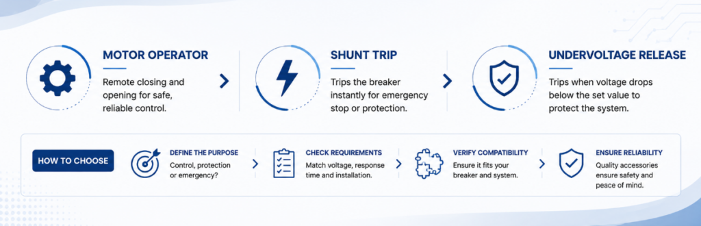
Motor operator vs shunt trip vs undervoltage release for MCCB accessory selectionRemote control is often over-specified because these accessories are treated as interchangeable. They are complementary, and the most expensive misunderstanding in the category is buying a shunt trip and discovering it cannot close the breaker again.
| Capability | Motor operator | Shunt trip (MX) | Undervoltage release (MN) | Auxiliary contact (OF) |
|---|---|---|---|---|
| Closes the breaker remotely | Yes, when the matched design permits | なし | なし | なし |
| Opens the breaker remotely | あり | あり | Yes, on supply loss | なし |
| Resets after a trip | Model-specific — confirm | なし | なし | なし |
| Reports breaker position | Not by itself | なし | なし | あり |
| Needs a continuous supply | No — draws only while operating | No — energised only to trip | Yes — held energised | No — volt-free |
| On loss of control supply | Breaker holds state; no remote control | Cannot trip | Trips — inherently fail-safe | Contact state unchanged |
| Typical role | Remote open, reset and close actuator | Fire-alarm or emergency trip path | Fail-safe trip and close permission | Command confirmation and interlocking |
Read the last two rows together. A shunt trip needs a healthy control supply to do its job; an undervoltage release does its job precisely when the supply is lost. Choose between them by asking what should happen if the control supply itself fails. A motor operator answers a different question: who closes the breaker when nobody is standing in front of it.
A motor operator may open the breaker mechanically and the project may still require a shunt trip, because protection or emergency circuits often need an independent, defined trip path. They are fitted together, not chosen between.
How a Motor Operator Actually Moves the Breaker
The command reaches the mechanism, a geared motor runs, and the breaker changes state. What happens between those points varies by design, and the difference affects command duration, timing and what the controller should expect after a power loss.
Direct drive. The motor moves the operating interface through the complete stroke while it is energised. The command must last long enough for the full travel, and the actuator movement broadly follows the breaker handle, which makes the operation easy to observe during commissioning.
Stored energy. The motor charges a spring, and the spring is then released to move the contacts in one fast action. This decouples contact speed from motor speed, which is what allows the contacts to close quickly enough to limit pre-arcing. The charging sequence and the contact operation are two separate events, and the controller should allow for both.
Neither approach is universally better. The decisive question is whether the complete breaker-and-mechanism assembly performs the required open, reset and close sequence on the available control supply and within the project timing. In both cases the motor stops once the operation completes, which is why a motor operator presents a large momentary demand and effectively no standing load.
Manual operation must remain defined either way. The current JUTRION portfolio page lists a built-in Auto/Manual switch for its motorised operating mechanism range. Confirm the ordered model’s mechanical engagement, whether MANUAL blocks remote commands, whether it disconnects motor power, and whether the controller receives selector-position feedback. A manual selector is not an isolation device and must be coordinated with the panel’s locking procedure.
Build the Command, Permission, Motion and Feedback Chain
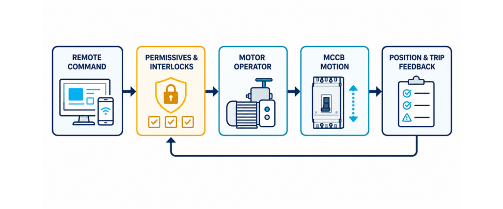
A dependable motor-control circuit has four linked functions. Each needs a defined input, output, failure response and commissioning test.
MCCB motorized operating mechanism control chain showing remote command, permissives and interlocks, breaker motion, and position and trip feedback.Command
- The command may come from local pushbuttons, a PLC output, a BMS relay, a transfer controller or a protection relay. Define whether the mechanism expects a pulse, a maintained signal, or separate OPEN and CLOSE inputs. Do not infer the arrangement from the control voltage. Commands must be mutually exclusive: if OPEN and CLOSE can be energised together through relay overlap or a software error, the circuit must resolve the conflict predictably.
Permission
- A command is a request, not authority to energise a circuit. Close permissives typically include healthy source voltage, no lockout active, breaker not in maintenance, alternate source open, trip cause cleared, and the selector in REMOTE. Opening usually has fewer permissives, but the required logic still belongs in the project cause-and-effect document rather than in an installer’s judgement.
Motion
- Once permitted, the mechanism draws control power and moves the breaker. The supply must hold its voltage through that transient demand. A supply that measures correctly at rest can dip when the motor starts, leaving the operation incomplete. Allow the manufacturer-declared operating time plus a supervision margin, and never issue rapid repeated commands to force completion.
フィードバック
- Confirm the physical state after the command. A position contact indicates ON or OFF; a separate alarm contact distinguishes a protective trip from a commanded opening. If the command expires without the expected state, raise a failure-to-open or failure-to-close alarm and block retries. That turns a silent failure into actionable diagnostic information.
Size the Control Supply on the Pickup Surge, Not the Holding Load
This is the calculation most often skipped, and it separates a panel that works from one that fails intermittently. Accessory coils draw two very different currents.
- Pickup (inrush) VA — the brief surge as the coil energises and the motor starts. It sets the momentary capability the supply needs and the voltage dip every other device on that supply will see.
- Holding VA — the continuous draw once energised. It sets the steady thermal load.
A supply that comfortably carries the holding load but sags during pickup will let the coil drop out, or prevent it pulling in at all. The device is not faulty; the supply is undersized for a demand lasting a fraction of a second.
Peak (pickup) demand:
Peak VA = Σ (pickup VA × quantity)
Peak current at the coil voltage:
Ipeak = Peak VA / V
Steady (holding) demand:
Steady VA = Σ (holding VA × quantity)
Recommended supply rating:
Illustrative first-pass supply = Peak VA × 1.25
The 1.25 multiplier is the illustrative allowance used by the JUTRION calculator, not a universal requirement stated by IEC 60947-2. Replace it where the power-supply manufacturer, control-transformer data, project standard, duty, temperature, or simultaneous-operation study requires a different margin.
Where several accessories can energise together — a motor operator running its cycle while an undervoltage release is held in — add their pickup figures. That combination, not any single device, is the worst case. The JUTRION breaker accessory power calculator runs these equations directly.
| Accessory | Pickup (VA) | Holding (VA) | 使用頻度 |
|---|---|---|---|
| Motor operator | Approx. 300–600 | 0 | Draws only during the operating cycle |
| Shunt trip (MX) | Approx. 100–300 | 0 | Momentary; energised only to trip |
| Undervoltage release (MN) | Approx. 200–350 | Approx. 5–10 | Continuously energised |
| Auxiliary / alarm contact | Negligible | Negligible | Volt-free contact |
These are the illustrative default ranges published by the JUTRION calculator, not IEC values or ordered-product ratings. Coil demand varies by series, frame and AC or DC type, so replace every default with the datasheet figure for the device actually ordered. The table is useful for understanding pickup versus holding duty, not for issuing a final transformer or power-supply specification.
Check the Volt Drop Before Choosing a 24 V DC Coil
Low-voltage DC is often specified for compatibility with a PLC rail or a UPS-backed control supply. For a motor operator it deserves a second look: the same power at a lower voltage means proportionally more current, and volt drop rises with it.
For a two-wire DC control circuit:
ΔU = 2 × L × I × ρ / A
Where ΔU is volt drop in V, L is the one-way run in m, I is the operating current in A, ρ is copper resistivity (about 0.0175 Ω·mm²/m at 20 °C, rising with temperature) and A is conductor area in mm². Rearranged for the permissible run:
Lmax = ΔU × A / (2 × I × ρ)
For an illustrative comparison, assume a mechanism with a 450 VA pickup demand and allow a 10% drop. The 450 VA value is a constructed input within the calculator’s typical range, not a JUTRION model rating:
| Coil voltage | Pickup current | Permitted drop | Max. run on 2.5 mm² | Max. run on 6 mm² |
|---|---|---|---|---|
| DC 24 V | 18.8 A | 2.4 V | Approx. 9 m | Approx. 22 m |
| DC 110 V | 4.1 A | 11 V | Approx. 192 m | Approx. 460 m |
| AC 220 V | 2.0 A | 22 V | Approx. 768 m | Approx. 1844 m |
Under these specific assumptions, the 24 V DC option on 2.5 mm² conductor reaches the 10% drop allowance at roughly nine metres. This is not a universal cable-length limit: the result changes directly with the ordered mechanism’s pickup demand, conductor size, temperature, terminal losses, and permitted operating-voltage range. For long control-room runs, compare a larger conductor, a local supply at the breaker, and a higher control voltage.
This is why accessory coils are offered across such a wide voltage range. JUTRION motorised operating mechanisms are available in AC 110 V, AC 220 V and AC 400 V, and in DC 24 V, DC 36 V, DC 110 V and DC 220 V, so the control voltage can be chosen to suit the cable run rather than the cable being sized around a voltage chosen by habit.
A Worked Example: 400 A Feeder with a Remote Motor Operator
The application. A 400 A MCCB feeds a pumping station from a control room about 60 m away. The breaker must be opened, reset and closed remotely. An undervoltage release is fitted so the breaker trips on loss of the control supply.
Step 1 — list what can energise together. The motor operator runs its cycle while the undervoltage release is held in. Both sit on the same control supply, so both count.
Step 2 — define illustrative inputs. Assume a motor operator at 450 VA pickup / 0 holding and an undervoltage release at 275 VA pickup / 7 VA holding. These constructed values sit within the JUTRION calculator’s illustrative ranges; replace them with the ordered accessory datasheets.
Step 3 — peak demand.
Peak VA = (450 × 1) + (275 × 1) = 725 VA
Step 4 — steady demand.
Steady VA = (0 × 1) + (7 × 1) = 7 VA
The ratio is the lesson: the momentary demand is more than a hundred times the continuous one.
Step 5 — size the supply.
Illustrative supply = 725 × 1.25 = 906 VA
Step 6 — check the voltage against the run. At DC 24 V the peak current is 725 / 24 = 30.2 A, and holding a 10 % drop over 60 m would need roughly 26 mm² — impractical for a control circuit. At AC 220 V the peak is 725 / 220 = 3.3 A and 2.5 mm² is comfortable with margin.
Illustrative result: AC 220 V is the more practical option for the assumed 60 m run. A control transformer around 1 kVA and 2.5 mm² conductors are the first-pass result under the stated inputs; final selection requires the transformer’s short-time regulation, protection, installation method, temperature, actual accessory data, and permitted voltage range. At DC 24 V, this example points toward a local supply or a substantially larger conductor.
Automatic Closing Needs Permissives, Interlocks and a Reset Policy
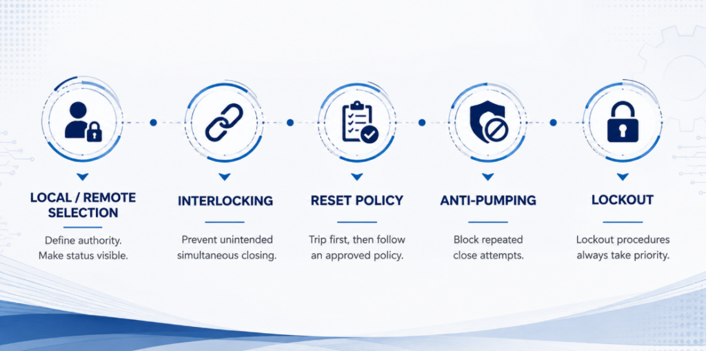
Automatic closing permissives, source interlocking, reset policy, anti-pumping and maintenance lockoutRemote opening is straightforward. Remote closing can energise damaged equipment, restart machinery, parallel sources, or expose people who believed a circuit would stay open. The close path deserves more engineering attention than the motor.
Local/remote selection. A selector defines who has authority. Its state should be visible to the controller, so a blocked command produces a clear “local mode” indication rather than a generic failure alarm.
Source interlocking. Where two breakers select between utility, generator or bus sources, logic must prevent unintended simultaneous closing unless the system is designed to parallel. Mechanical interlocking adds a physical layer, but its compatibility must be verified with the chosen breakers and mechanisms.
Reset and reclose policy. A protective trip should normally block automatic closing until the cause is classified. Some systems permit one supervised reclose for a defined transient; others require investigation after every trip. The motor operator executes the approved policy — it should not create one by default.
Anti-pumping. If a CLOSE command remains present while the breaker trips, the system must not cycle between closing and tripping. The control architecture should block repeated attempts until the command is removed and a new authorised sequence begins.
Maintenance lockout. Software inhibition is not a substitute for an approved lockout procedure. A remote system can issue commands unexpectedly during testing, communication recovery or a software restart.
Apply the Logic to Three Common Architectures
Generator and Source Transfer
Two breakers, each with a motor operator, are switched by a transfer controller so that only one is ever closed. A motor operator is essential because the controller must 投入 a breaker, not merely trip one.
The controller opens the active source, confirms it is open through position feedback, and only then permits the alternate source to close. Interlocking is mandatory. The control supply must also be available from whichever source is live — a detail easily missed when the control transformer is fed from the utility side alone.
Key distinction: a motor operator supplies motion; it does not by itself make two breakers a transfer switch.
Unattended Site or Remote Substation
A breaker in a rooftop plant room, a pumping station or an unmanned substation is motorised so a trip can be investigated and supply restored without a site visit. The cable run is usually long, which makes the control-voltage decision the governing constraint rather than the mechanism. Fit an alarm contact alongside the position contact so the control system can distinguish a fault trip from a commanded opening before anyone attempts a remote reset.
Load Shedding and Scheduled Switching
An energy-management system opens non-critical feeders when generator capacity or site demand reaches a limit, then restores them in stages to avoid a second demand peak. Each feeder needs a priority, a minimum off time, a close permissive and a failure alarm.
One opening and one closing movement per day totals about 10,950 movements over fifteen years. Confirm how the ordered mechanism defines an operation or cycle before comparing this figure with endurance. Frequent routine switching may belong to a contactor, with the breaker left to provide protection and isolation.
Retrofitting a Motor Operator to a Breaker Already Installed
Most writing on this subject assumes breaker and accessory are specified together. A large share of real enquiries are the opposite: the breaker has been in service for years, the requirement for remote operation appeared later, and the question is whether a mechanism can be added without replacing it.
Some installed MCCBs can accept a retrofit operator without replacing the breaker. Where the approved mechanism mounts on the front, the current path and trip settings may remain unchanged, but the panel must be isolated and the breaker condition checked before installation. Three things decide whether the retrofit is practical:
- Series and frame. The mechanism is matched to the specific breaker, not to its ampere rating. Two 250 A breakers from different series will usually need different mechanisms.
- Front clearance. A motor operator adds depth. Check the distance to the enclosure door and to any escutcheon before ordering.
- Control supply. An existing panel may have no control transformer or DC supply, or one without the capacity calculated above. On retrofits this is more often the real constraint than the mechanism.
Brand is not an automatic barrier. Model-specific adaptation can cover approximately 99% of mainstream breaker designs, with the mounting interface, terminal layout and coil voltage matched to the target breaker. This percentage describes the breadth of an adaptation programme; it does not mean that one universal mechanism fits every MCCB.
Compatibility check: record the breaker manufacturer, series, frame and number of poles, then provide clear nameplate and front-view photographs. These inputs allow the mounting interface and operating travel to be checked before a mechanism is selected.
A serviceable breaker may then gain remote operation without replacement, subject to its condition, available space, required documentation and an approved mechanism match.
Check the Supporting Accessory Options
A complete MCB・MCCB付属装置シリーズ 電動操作機構、引外しコイル、不足電圧引外し装置、補助接点、警報接点などがあります。以下の表はこれらの制御側機能を比較したもので、機械的な取り付け可否は遮断器の銘板で確認する必要があります。.
| Accessory | 制御電圧オプション | 構成 | 定格耐久性 |
|---|---|---|---|
| 電動操作機構 | AC 110 V、AC 220 V、AC 400 V;DC 24 V、DC 36 V、DC 110 V、DC 220 V | 自動/手動切替器内蔵 | 遠隔操作10,000回 |
| 引外しコイル(MX / ST) | AC 230 V、AC 400 V;DC 24 V | 瞬時引外し | 引外し動作4,000回 |
| 不足電圧引外し装置(MN / UVR) | AC 230 V、AC 400 V;DC 24 V、DC 48 V | 定格電圧の35%~70%で開放n | 引外し動作4,000回 |
| Auxiliary contact (OF) | 無電圧 | 1NO+1NC、または2NO+2NC | 電気的サイクル10,000回 |
| 警報接点(SD) | 無電圧 | 1NO+1NC、または2NO+2NC | 電気的サイクル10,000回 |
広い電圧範囲により、制御電源を設備に合わせて選択できます。同一配電盤内ではDC 24 VがPLCロジックと容易に統合でき、長距離配線ではより高い制御電圧により導体所要量を低減できる場合があります。.
公開されている製品諸元では、機構カテゴリで遠隔操作10,000回、引外し付属装置で引外し動作4,000回と記載されています。プロジェクトの使用頻度と比較する前に、発注モデルが動作をどのように定義・試験しているかを確認してください。頻繁な通常開閉が必要な場合は 接触器 を使用してください。.
電動操作機構の故障を招く8つのミスを回避
| ミス | 結果 | 防止策 |
|---|---|---|
| 「遠隔制御」用に引外しコイルを指定する“ | 遠隔では引外しできるが、投入は盤面で手動操作が必要 | まず遠隔投入が必要かどうかを確認する |
| 遠隔投入にトリップ状態からのリセットが含まれると想定する | 故障引外し後、遮断器が投入できない | 仕様に「トリップ後の遠隔リセット」を明記する |
| 保持VAで制御電源容量を選定する | 機構が間欠的に引き込めない | 合成された起動時要求容量で選定し、文書化されたプロジェクト余裕を適用する |
| 長距離配線にDC 24 Vを選択する | 電圧降下により確実な動作ができず、機構不良と誤診断される | 電圧を確定する前に実際の配線長で電圧降下を確認する |
| 付属装置の同時動作を無視する | 1台には十分な電源が、2台同時励磁時に低下する | 同時に励磁され得るすべての起動VAを合算する |
| アンペア定格だけで適合させてしまう | 付属装置が取り付けられない、または扉と干渉する | 銘板でシリーズ、フレーム、クリアランスを確認する |
| 個別のトリップ/警報接点を省略する | システムが故障トリップと指令による開放を区別できず、故障のまま再投入する恐れがある | 位置接点と警報接点を取り付け、両方を配線する |
| 試運転後に切替器をMANUALのままにする | 遠隔指令が黙って無視される | 引き渡し時に切替器の位置を確認し記録する |
制御チェーンをたどって故障を診断する
| 症状 | 考えられる箇所 | 収集すべき証拠 | 安全な次の対応 |
|---|---|---|---|
| モーターが動作しない | 電源欠落、セレクターがMANUAL、指令なし、許可条件が開、制御ヒューズ | 電源端子と指令端子の電圧、セレクターとPLCの状態 | 何かを交換する前に指令と許可条件をたどる |
| モーターは動作するが、ブレーカーが状態変化しない | 機械的不整合、芯ずれ、ブレーカーがTRIPPEDのまま、リセット不完全 | ブレーカー表示、手動動作、芯合わせ | 制御電源を切り離し、機械的インターフェースを点検する |
| ブレーカーは位置に達するがPLCが故障表示 | 補助接点の誤り、NO/NCの解釈違い、フィードバック配線の断線、タイマーが短すぎる | ブレーカーとコントローラーでの接点状態、実測動作時間 | やみくもにタイマーを延ばすのではなく、フィードバックロジックを修正する |
| 動作中に制御電圧が低下する | 電源容量不足、長距離配線、細い導体、同時負荷 | 最低電圧 機構部で 動作中に | モデル固有のデータを用いて電源回路を修正する |
| 現場では動作するが、制御室からは動作しない | 長距離配線での電圧降下、中継点での端子の緩み | 実際のサイズと長さで電圧降下を再計算し、端子を点検する | 導体を太くするか、制御電圧を変更する |
| ブレーカーが投入とトリップを繰り返す | 故障が未解消、投入指令が保持されている、アンチポンピングロジックの欠落 | トリップ表示、指令履歴、保護イベント | 再投入をブロックし、保護対象回路を調査する |
許可条件のバイパスやハンドルの強制操作から診断を始めないこと。まず指令、許可、動作、フィードバックの4つの機能のうちどれが失敗したかを特定する。これにより、制御ロジックの故障を機械的故障と誤認することを防ぎ、ブロックまたはトリップしたブレーカーに対して繰り返し操作を行うことを防ぐ。.
機構を選定する前にこれらのパラメーターを記録する
- ブレーカー銘板の写真 — これでブランド、シリーズ、フレーム、定格が一度に確定する
- 銘板にアクセスできない場合のブレーカーのブランド、シリーズ、モデル
- 極数と取り付け向き
- 必要な機能:遠隔開放、トリップ後の遠隔リセット、遠隔投入、または3つすべて
- 利用可能な制御電圧、ACまたはDC、およびその供給源
- 制御電源からブレーカーまでのケーブル配線長
- 指令方式:パルス、保持、またはOPENとCLOSEの個別入力
- 同時に取り付ける他の付属品
- 位置およびトリップ原因に必要なフィードバック接点
- 1日または1年あたりの想定動作回数
- 制御電源が失われた場合に何が起きるべきか
- 筐体の奥行きと扉のクリアランス
- 対象市場とプロジェクトに必要な文書
技術提出書類で確認すべきこと
有用な技術提出書類は、単にブレーカー電流を繰り返すのではなく、指定されたブレーカーに適合する正確な機構を特定すべきである。制御電圧の指定、開放・投入入力の構成、リセット能力、ピックアップ電力または電流、動作時間、機械的耐久性、端子図、全体寸法、適合する補助接点構成を確認すること。また、機構が前面取り付けの完全なアセンブリなのか、別個のブラケット、カプラー、配線付属品が必要なのかも明記すべきである。.
改造の場合、取付インターフェースと追加奥行きを示す図面を要求してください。自動電源切替またはインターロック付きフィーダ用途の場合、指令真理値表も要求してください。ON、OFF、TRIPPED状態でどの入力が受け付けられるか、指令がどれだけの時間保持される必要があるか、動作途中で電源が消失した場合に何が起こるか。これらの詳細により、互換性の主張が、盤製作者が確認できるインターフェースへと変わります。.
If two mechanisms use different pickup values, operating times or reset sequences, they are not directly equivalent even when both carry the same product description. Compare the complete control function and installation requirements, not the actuator rating alone.
よくある質問
モーターオペレーターとシャントトリップの違いは何ですか?
モータオペレータは、互換性のあるMCCBを機械的に開路、リセット、閉路します。シャントトリップは、コイルが励磁されるとブレーカを電気的にトリップさせ、リセットや閉路はできません。自動化システムでは、異なる機能のために両方が使用されることがよくあります。.
モーター操作器はトリップ後にブレーカーをリセットできますか?
適合した機構はリセット動作を実行できますが、それはモデル固有です。お使いの遮断器にリモートリセットが対応していることを確認し、制御システムが投入指令を受け付ける前にトリップ状態を解除することを必須としてください。.
他社製のブレーカーにモータ操作器を取り付けることはできますか?
対象となる遮断器に対して機構が適合・検証されている場合、異なるブランド間での取り付けが可能です。定格電流だけで互換性を判断することはできません。銘板、寸法データ、正面写真から、製造元、シリーズ、フレーム、極数、取り付けインターフェース、操作ストロークを確認してください。.
既に設置済みのブレーカーにモーター操作器を追加できますか?
一部の設置済みMCCBは、遮断器を交換することなく前面取付形操作器を取り付けることができます。改造を承認する前に、遮断器の状態、シリーズ、フレーム、ハンドルインターフェース、前面クリアランス、取付ポイント、制御電源、フィードバック配線、および必要なプロジェクト文書を確認してください。.
Which control voltage should I choose?
Choose it from the cable run, not from habit. Calculate the pickup current at each candidate voltage and check volt drop over the actual distance. Within a switchboard DC 24 V is convenient; over a long run an AC 220 V coil usually gives a far simpler cable.
Does a motorised MCCB close automatically after a fault?
Not safely by default. Automatic closing requires an approved reset policy, a cleared trip condition, healthy permissives, correct interlocking and confirmed feedback. Many installations require manual authorisation after any protective trip.
Final Engineering Check
- Remote closing is genuinely required, not just remote tripping
- Reset from TRIPPED is specified explicitly if the breaker must recover from a fault trip
- Breaker series, frame and mounting confirmed from the nameplate
- Pickup and holding VA taken from the datasheet, not assumed
- Combined pickup demand calculated for everything that can energise together
- Control supply sized for combined pickup demand, with the margin required by the selected supply, project and installation conditions
- Control voltage chosen after checking volt drop at the actual run
- Behaviour on loss of control supply decided, with an undervoltage release if required
- Position and trip/alarm contacts specified and wired
- Close permissives, interlocking and anti-pumping defined in the control logic
- Expected operations per year checked against rated endurance
- Front clearance verified and the selector position recorded at commissioning
Specify the Control Chain Before the Mechanism
The mechanism is the straightforward part. What determines whether the installation works is everything around it: whether the control supply holds its voltage through a surge many times the steady load, whether the chosen coil voltage survives the distance, and whether the logic can tell a tripped breaker from an open one.
The practical order is: confirm remote closing is required, identify the breaker from its nameplate, decide which motions are needed including reset, choose the control voltage from the cable run, size the supply on combined pickup demand, then settle feedback, interlocking and endurance.
For further selection context, see the guide to circuit breaker accessories. To check an exact mechanism match, provide the breaker nameplate, front-view photograph and project requirements so the complete assembly can be reviewed before installation.
Technical References and Data Boundaries
The sources serve different purposes. IEC 60947-2:2024 provides the product-standard framework for low-voltage circuit-breakers; it is not cited as the source of the 1.25 illustrative supply allowance, typical accessory VA ranges, JUTRION control-voltage options, endurance figures, or 99% adaptation coverage. Those values come from the current JUTRION accessories page and breaker accessory power calculator. Exact electrical demand, timing, operating-voltage limits, and compatibility must come from the ordered accessory documentation.
- IEC 60947-2:2024 — Low-voltage switchgear and controlgear — Part 2: Circuit-breakers (sixth edition, September 2024; supersedes the 2016 fifth edition and its Amendment 1:2019). UL 489 applies to moulded-case circuit breakers in North American markets.
