

빠른 사이징 답변
태양광 DC 회로 차단기를 단선 결선도상의 실제 위치에서 사이징하십시오. 전압에는 저온 보정된 스트링 Voc 를 사용하고, 전류에는 모듈 Isc 에 병렬 스트링 수와 프로젝트의 요구 계수를 곱한 값을 사용한 다음, 케이블 보호, DC 차단 용량, 극 배선 및 함체 감격을 확인하십시오. 이러한 역할이 확인된 후에만 MCB 또는 MCCB를 선택하십시오.
동일한 PV 어레이라도 한 스트링에서는 20 A 기기가, 컨바이너 출력에서는 100 A 기기가 필요할 수 있습니다. 두 기기는 거의 동일한 스트링 전압을 보지만, 동일한 전류를 흘리거나 동일한 도체를 보호하지는 않습니다. 이것이 “1000 V DC 태양광 차단기”와 같은 요청만으로는 모델 선택이 불가능한 이유입니다.
첫 번째 질문은 차단기 사이즈가 얼마인가? 가 아닙니다. 차단기가 어디에 있고, 그 지점의 고장에 무엇이 전류를 공급할 수 있는가?
입니다.
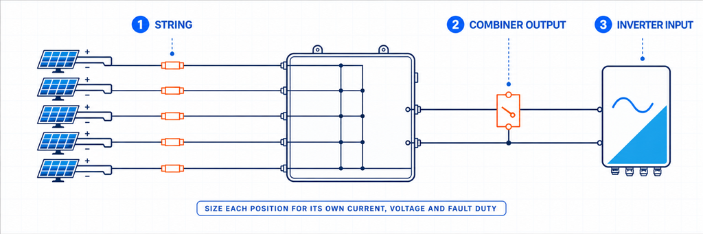
PV 보호 맵에 차단기 배치하기스트링, 컨바이너 출력 및 인버터 입력 차단기 위치를 보여주는 태양광 PV DC 보호 맵
태양광 어레이는 전기적으로 서로 다른 회로의 연쇄입니다. 카탈로그를 열기 전에 제안된 차단기를 표시하십시오:
PV 스트링 → 스트링 컨바이너 입력 → 결합된 DC 출력 → 인버터 DC 입력.
| 오른쪽으로 한 위치 이동하면 전류 경로가 달라집니다. 직렬 모듈은 전압을 높입니다. 호환 가능한 병렬 스트링은 전류를 높입니다. 개별 입력의 차단기는 일반적으로 하나의 스트링을 담당하고, 공통 출력의 차단기는 해당 출력에 연결된 모든 스트링을 담당합니다. | 위치 | 기기를 통과하는 전류 | 확립해야 할 주요 역할 |
|---|---|---|---|
| 일반적인 후보 목록 | 개별 스트링 | 하나의 스트링 | 역전류 보호 및 스트링 분리 |
| 설계상 허용되는 경우 gPV 퓨즈 또는 PV 정격 DC MCB | 컨바이너 출력 | 병렬 스트링의 합 | 결합된 피더 및 출력 케이블 보호 |
| PV 정격 DC MCB, DC MCCB 또는 별도 보호가 있는 스위치 단로기 | 인버터 DC 입력 | 해당 인버터 입력 또는 MPPT 경로에 할당된 전류 | 기기 분리 및 조정된 보호 |
시스템 설계에 의해 지정된 차단기 또는 스위치 단로기.
표는 의도적으로 “후보 목록”이라고 말합니다. 모든 위치에 회로 차단기가 자동으로 필요한 것은 아닙니다. 스트링은 gPV 퓨즈를 사용할 수 있고, 인버터는 이미 적절한 DC 절연기를 포함할 수 있으며, 출력은 과전류 보호가 다른 곳에서 제공되는 동안 분리만 필요할 수 있습니다. 기기를 선택하기 전에 누락된 기능을 정의하십시오. 에 관한 기사는 태양광 컨바이너 박스 사이징.
MPPT 그룹화가 어떤 스트링이 출력을 공유할 수 있는지 결정하는 방법을 설명합니다. 먼저 그 아키텍처 결정을 완료하십시오. 차단기는 애초에 병렬로 연결되어서는 안 되는 스트링을 바로잡을 수 없습니다.
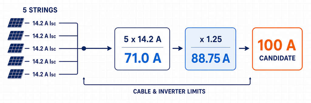
최소 암페어 정격이 아닌 전류 범위 설정하기5개의 병렬 스트링에서 100암페어 후보까지의 태양광 DC 회로 차단기 전류 사이징.
전류 계산에는 두 가지 측면이 있습니다. 차단기는 설치 조건에서 설계 전류를 견뎌야 하지만, 보호되는 케이블이나 연결된 기기가 한계를 벗어날 정도로 커서도 안 됩니다.
I정합된 PV 스트링의 경우: sc,pathp = N× I
sc,module
- I정합된 PV 스트링의 경우: 여기서:;
- Np 는 선택된 경로의 단락 전류 기준값(암페어)입니다.;
- I× I 는 해당 경로에서 병렬로 연결된 스트링 수입니다.
는 명시된 시험 조건에서의 모듈 단락 전류입니다.
I프로젝트의 설치 방식에 따라 설계 전류 처리가 결정됩니다: 를 제공합니다. 실제 설치는 더 뜨겁거나, 그룹화되거나, 단열재로 감싸여 있어 도체가 과열되기 전에 흐를 수 있는 전류가 모두 감소합니다. 설치 용량은 적용 가능한 모든 계수로 스케일된 기본 값입니다:정합된 PV 스트링의 경우: design프로젝트
K프로젝트 추측할 숫자가 아닙니다. 이는 채택된 설치 규칙과 설계 기준에 따라 요구되는 현재 계수를 나타냅니다. 북미 사례는 장비 정격과 계산 경로에 따라 일반적으로 1.25 또는 1.56을 보여줍니다. IEC 중심 프로젝트는 해당 수치 중 하나를 보편적인 “IEC 배율”로 재명명하는 대신 적용 가능한 설치 요구 사항, 모듈 데이터 및 제조업체 지침을 사용해야 합니다.”
유용한 선택 창은 다음과 같습니다:
요구 통전 전류 ≤ 사용 가능한 차단기 정격 또는 설정 ≤ 허용 보호 회로 한계
상한 경계는 절감된 케이블 허용 전류, 단자 정격, 인버터 입력 한계 또는 다른 보호 구성 요소에 의해 설정될 수 있습니다. I 위의 다음 표준 차단기를 선택하는 것은프로젝트의 설치 방식에 따라 설계 전류 처리가 결정됩니다: 상한 경계가 여전히 통과할 때만 유효합니다.
직렬 모듈은 차단기 전류를 곱하지 않습니다
직렬로 연결된 20개의 모듈은 모듈 전류의 20배를 생성하지 않습니다. 이들은 스트링 전압을 증가시키는 반면 스트링 전류는 하나의 모듈을 기준으로 유지됩니다. 병렬로 연결된 5개의 동일한 스트링은 약 5배의 전류를 생성합니다. 이것이 어레이 와트를 가정된 DC 전압으로 나누는 것이 모듈 데이터시트 및 스트링 일정의 빈약한 대체물인 이유입니다.
I 사용sc 및 IMP 다른 점검을 위해
Isc 는 PV 과전류 설계에 사용되는 단락 전류 시작점입니다. IMP 는 최대 전력 부근의 작동 전류를 설명하며 인버터 MPPT 부하 및 정상 작동을 확인하는 데 도움이 됩니다. 두 값을 모두 워크시트에 유지하십시오. 보호 기준을 더 낮은 I로 대체하지 마십시오MP, 그리고 I에서 계산한 후 인버터의 작동 전류 한계를 잊지 마십시오sc.
IEC 및 북미 사례를 각자의 영역에 유지하십시오
예를 들어 Eaton의 북미 PV 적용 가이드는 80% 정격 및 100% 정격 몰드 케이스 차단기를 구분합니다. 그 작업 방법은 80% 정격 차단기에 대해 1.56 × I를 사용하고sc 100% 정격 차단기에 대해 1.25 × I를 사용합니다sc , 도체 및 온도 점검과 함께. 해당 수치는 해당 NEC/UL 및 제품 맥락 내에서 유용합니다. 이를 분리하여 글로벌 PV 규칙으로 게시해서는 안 됩니다.
IEC 프로젝트의 경우 계약 또는 관할권에서 채택된 판부터 시작하십시오. IEC 60364-7-712의 공개 범위는 PV 전기 설치를 다루는 것을 확인하지만, 범위 페이지가 특정 프로젝트에 대한 완전한 계산을 설정하지는 않습니다. K 옆에 실제 설계 규칙을 기록하십시오프로젝트; 이렇게 하면 산술 검토가 가능하고 공급업체가 조용히 방법을 전환하는 것을 방지할 수 있습니다.
저온 V에서 전압 정격 설정oc 및 극 다이어그램
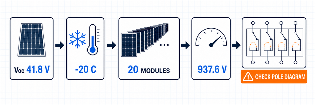
저온 PV 스트링 전압 계산 및 DC 회로 차단기 극 구성 점검스트링 전압은 모듈이 개방 회로이고 저온일 때 가장 높습니다. 모듈의 STC V에서 선택된 차단기는oc 추운 아침에 정격 미달일 수 있습니다.
모듈이 섭씨당 퍼센트 단위의 음의 V 온도 계수를 제공하는 경우 예비 계산은 다음과 같습니다:oc oc,cold,module
Voc,cold,string = Voc,STC × [1 + |βVoc| × (25 − Tmin)]
V× V sc,paths 여기서 Noc,cold,string
은 직렬 모듈 수이고 Ts 는 프로젝트의 최소 설계 온도입니다. −0.27%/°C를 0.0027로 입력하십시오. 모듈 제조업체 또는 채택된 설계 방법이 다른 온도 계산을 지정하는 경우 인버터 및 모든 DC 구성 요소에 걸쳐 일관되게 사용하십시오.min 차단기의 선언된 DC 전압은 승인된 최대 회로 전압 이상이어야 합니다. 또한 제조업체가 표시한 정확한 극 배열에서 해당 정격을 달성해야 합니다. 일부 고전압 DC 차단기는 아크 차단을 공유하기 위해 여러 접점을 직렬로 배치합니다. 4극 본체가 자동으로 1000V 또는 1500V 차단기와 같지는 않습니다.
주문 전에 다음을 확인하십시오:.
정확한 모델에 대한 정격 작동 DC 전압;
- 해당 전압에서 직렬로 사용되는 극 수;
- 허용된 양극 및 음극 도체 경로;
- 극성 민감도 및 라인/부하 방향;
- 절연 기능이 요구되는 경우 절연에 대한 선언된 적합성.;
- 기존.
JUTRION 저온 스트링 전압 계산기 는 1차 통과 V 결과를 제공할 수 있습니다 . 이는 PV SPD 전압 스크리닝을 위해 만들어졌지만 저온 스트링 전압은 차단기, 절연기, 케이블 및 인버터 점검에 대한 입력이기도 합니다.× V 고장 경로를 사용하여 차단기가 회로를 보호할 수 있는지 결정하십시오.
차단기의 정격 전류와 차단 용량은 다른 질문에 답합니다:
정격 전류 또는 트립 설정:
- 장치가 정상 전류를 전달하고 적용 가능한 과전류로부터 회로를 보호할 수 있습니까? DC 차단 용량:
- DC 차단 용량: can it safely interrupt the prospective fault current at the stated DC voltage and wiring condition?
Do not compare a 100 A breaker rating with a 50 A reverse-current contribution and conclude that the device can interrupt the fault. A normal-current label does not prove trip response, conductor protection or DC interruption performance.
At a string fault, healthy parallel strings may feed reverse current into the damaged string. An initial screen is:
I역방향, 화면 = (Np − 1) × I단락, 문자열
This shows why reverse-current exposure grows as more strings are paralleled. It does not by itself select a breaker or fuse. The final design must consider the module’s maximum series-fuse rating, conductor capacity, protective-device characteristic and the requirements of the adopted installation rules.
At a combined output, identify every source that can feed the fault. PV modules are current-limited compared with a utility or battery, but parallel sub-arrays, connected power-conversion equipment and any storage interface can change the available current. If batteries are connected at DC level, stop treating the circuit as a PV-only example; battery fault-current assessment deserves its own design.
Do Not Assume a Large Breaking Number Solves a Poor Trip Decision
A breaker may have ample ultimate interruption capacity and still fail to protect the intended conductor because its trip threshold or time-current response is unsuitable. Conversely, a low-current breaker can have a normal rating close to the load yet lack the required DC breaking capacity at the actual voltage. Verify both the interruption rating and the protective characteristic.
PV faults can also occur near the lower end of a breaker’s operating range. Selectivity between string devices and an output breaker is not guaranteed simply because the output device has the larger ampere label. Use manufacturer coordination data where selective operation matters, and treat the claimed trip curve as model-specific evidence rather than a generic “C-curve for solar” rule.
IEC 60947-2:2024 applies to circuit breakers for instructed or skilled persons with rated voltages up to 1000 V AC or 1500 V DC. That product-standard scope supports the key procurement rule: obtain verified DC ratings for the exact breaker, not an AC breaking figure or a family-level marketing label.
Choose DC MCB or DC MCCB After the Duty Is Visible
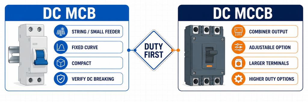
DC MCB versus DC MCCB comparison for solar string and combiner output protection“Use an MCB below 63 A and an MCCB above 63 A” is convenient, but it is not a universal engineering boundary. Product ranges overlap. Some DC MCB families extend above 63 A; some projects choose an MCCB at a lower current because they need a different breaking capacity, adjustable protection, larger terminals or accessories.
| Project need | DC MCB is the stronger shortlist when… | DC MCCB is the stronger shortlist when… |
|---|---|---|
| Installation format | A compact DIN-rail device fits the string or small feeder | A molded-case panel device, larger conductors or busbars are involved |
| Protection adjustment | The declared fixed characteristic suits the circuit | An available adjustable trip unit helps coordinate the feeder |
| Breaking duty | The model’s verified DC breaking capacity exceeds the fault level | The circuit requires a higher verified DC interruption duty |
| Control and indication | Basic handle position or modular auxiliary options are sufficient | Shunt trip, auxiliary contacts or remote operation are required and supported |
| Typical PV position | Individual string or lower-current branch | Combiner output or higher-current array feeder |
The decision is not about which family is “better.” It is about which verified product satisfies the location’s current window, voltage/pole arrangement, interruption duty, cable interface and control requirements. After those values are known, compare the available JUTRION DC MCB configurations 그리고 JUTRION DC MCCB configurations.
Decide Whether the Location Needs a Fuse, Breaker or Isolator
Three devices often appear in the same combiner box, but their jobs are not interchangeable.
- gPV fuse and holder: provides PV string or array overcurrent protection within its verified duty. It does not provide maintenance isolation unless the complete fuse-switch arrangement is designed for that function.
- DC 회로 차단기: provides automatic overcurrent operation plus switching within its declared ratings. It does not automatically satisfy a required isolating function unless it is declared suitable for isolation.
- DC switch-disconnector: provides manual load switching and isolation within its utilization rating. It does not provide automatic overload or short-circuit protection.
At string level, gPV fuses are common because parallel strings can feed reverse current into a faulted string and the module provides a maximum series-fuse rating. A resettable breaker may be useful where its PV duty and characteristic are verified, but “resettable” is not evidence that it coordinates better.
At a combiner output, a breaker may protect the combined cable and provide switching. Another design may use a switch-disconnector because overcurrent protection is located elsewhere. State which function the device performs; otherwise two suppliers can quote different architectures under the same “DC breaker” request.
Coordinate the Breaker with the Complete DC Path
A correct breaker can still be wrong in an incorrectly coordinated system. Complete five checks before freezing the model.
Cable
Verify conductor ampacity after ambient-temperature, grouping, installation and termination corrections. The breaker rating or setting must remain within the permitted protection relationship. Do not increase the breaker solely to stop nuisance trips without reviewing the enclosure temperature and cable.
Inverter
Compare cold string voltage with maximum DC input voltage. Compare the parallel-string operating current with the MPPT/input-current limit, and total Isc with the inverter’s permitted short-circuit current. The breaker does not authorize an array that exceeds the inverter data.
String fuses
Confirm whether each string needs reverse-current protection and whether the selected fuse/link remains below the module maximum series-fuse rating while carrying the required current under enclosure conditions. The common output breaker and string fuses normally protect different conductors.
태양광 DC 서지 보호 장치 (PV DC SPD)
An SPD limits transient overvoltage; it is not the normal overcurrent device. Follow the SPD manufacturer’s backup-protection instructions and check its short-circuit behavior. The guide to selecting a DC SPD for solar PV covers UCPV, Type 2/Type 1+2 and protection-level decisions.
Enclosure and assembly
Outdoor combiner boxes can run substantially hotter than the surrounding air. Use the breaker’s actual temperature/altitude data, terminal limits and mounting instructions. Closely spaced protective devices, solar heating, cable losses and restricted airflow all affect usable current. Review the complete PV combiner-box assembly, not only the breaker nameplate.
If a catalogue curve shows that the breaker carries less current at the expected internal temperature, apply that curve before choosing the frame. If no applicable curve or assembly data is available, increasing the breaker rating by an improvised percentage is not a defensible thermal design. The larger breaker may also require a larger conductor, terminal or enclosure and may no longer protect the original cable.
IEC 62548-1:2023 covers PV array design requirements including DC wiring, electrical protection devices, switching and earthing provisions. IEC 60364-7-712:2025 applies to electrical installations of PV systems. These installation contexts are distinct from the circuit-breaker product standard.
One Array, Three Different Breaker Decisions
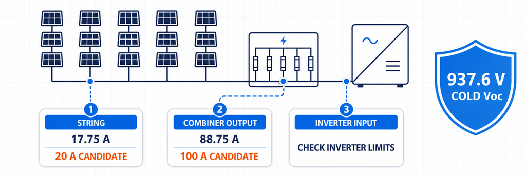
Solar DC breaker sizing example comparing string, combiner output and inverter input decisionsIllustrative design: each string has 20 identical modules. Module data states Voc,STC = 41.8 V, Isc = 14.2 A and βVoc = −0.27%/°C. The minimum design temperature is −20°C. Five compatible strings feed one inverter input through a combiner. For this example only, the project’s preliminary current method uses 1.25 × Isc.
First, establish the common voltage duty
Cold module Voc = 41.8 × [1 + 0.0027 × (25 − (−20))] = 46.88 V
Cold string Voc = 20 × 46.88 = 937.6 V
The strings are in parallel at the combiner, so their voltages do not add. The string device and the output device both require a verified voltage/pole arrangement above the approved maximum circuit voltage. A 1000 V DC class is the initial shortlist, subject to the project’s additional voltage treatment and the exact breaker diagram.
Position 1: one string
Preliminary string design current = 14.2 × 1.25 = 17.75 A
A 20 A PV-rated protective device is the first current candidate. Before choosing a DC MCB, compare this result with the module maximum series-fuse rating, conductor ampacity, required reverse-current protection and the exact trip characteristic. A gPV fuse may remain the better string-protection choice.
With five strings in parallel, the four healthy strings produce an initial reverse-current screen of:
(5 − 1) × 14.2 = 56.8 A
That figure explains why string protection deserves attention. It does not mean a 56.8 A string breaker should be fitted.
Position 2: combiner output
Total Isc = 5 × 14.2 = 71.0 A
Preliminary output design current = 71.0 × 1.25 = 88.75 A
A 100 A-class DC breaker is a current shortlist for the combined output. The handoff from MCB to MCCB now depends on the available product range, verified DC breaking capacity, required settings, terminal size and enclosure temperature—not on a universal 63 A rule.
Position 3: inverter input
The current arithmetic may be identical to the combiner output because it is the same feeder. The decision is not automatically identical. Confirm whether the inverter already provides a DC switch, whether an external breaker is required, the maximum input current and Isc, the permitted switching arrangement and the location needed for safe maintenance.
| 오른쪽으로 한 위치 이동하면 전류 경로가 달라집니다. 직렬 모듈은 전압을 높입니다. 호환 가능한 병렬 스트링은 전류를 높입니다. 개별 입력의 차단기는 일반적으로 하나의 스트링을 담당하고, 공통 출력의 차단기는 해당 출력에 연결된 모든 스트링을 담당합니다. | Calculated current starting point | Initial device direction | Decision that remains |
|---|---|---|---|
| 개별 스트링 | 17.75 A | 20 A PV protective device candidate | gPV fuse or DC MCB; module/cable coordination |
| 설계상 허용되는 경우 gPV 퓨즈 또는 PV 정격 DC MCB | 88.75 A | 100 A-class DC breaker candidate | MCB/MCCB, DC breaking capacity, settings and temperature |
| Inverter input | Same feeder current | Breaker or switch-disconnector as required | Inverter limits and whether protection already exists |
The calculation has produced three different functional decisions from one array. That is more useful than quoting one breaker size for “a 100 kW solar system.”
Read the Breaker Datasheet as a Connected Rating Set
Do not approve the device by circling one number. Read these ratings together:
- Ue: rated operational voltage for the stated DC pole arrangement;
- In or frame/setting: current rating and available adjustment under reference conditions;
- DC 차단 용량: declared interruption performance at the relevant DC voltage;
- trip characteristic: how and when the device operates, not simply a B/C/D letter borrowed from another family;
- isolation declaration: whether it can serve the required isolating function;
- pole and polarity diagram: the only valid connection for the declared high-voltage rating;
- temperature and altitude data: the basis for usable current in the real enclosure;
- terminals: conductor range, material, preparation and tightening torque;
- accessories: auxiliary contacts, shunt trip or remote operation where the system needs them.
A label such as “4P, 1000 V DC, 100 A” does not disclose the complete connected rating set. Ask for the exact technical sheet and wiring diagram for the ordered model.
Three Datasheet Warning Signs
- One breaking-capacity number with no DC voltage: interruption performance must refer to a stated voltage and test arrangement.
- A 1000 V claim with no pole diagram: the buyer cannot confirm how the arc chambers share voltage or where the conductors connect.
- One current rating with no reference temperature: the rooftop enclosure duty remains unknown.
These omissions do not automatically prove that a product is unsuitable, but they prevent an engineering selection. Resolve them before the device is installed in a live PV string.
자주 묻는 질문
태양광 패널에는 어떤 크기의 DC 차단기가 필요합니까?
Use module Isc and the number of parallel strings on the protected path, then apply the current method required by the project. Select the next suitable rating only if it also protects the derated cable and stays within inverter and terminal limits. Check cold Voc, DC breaking capacity and pole wiring separately.
태양광 DC 측에 AC 차단기를 사용할 수 있나요?
제조업체가 해당 DC 애플리케이션에 대해 정확한 기기, DC 전압, 차단 용량 및 극 배치를 명시적으로 선언한 경우에만 해당합니다. AC 정격만으로는 충분하지 않습니다. 지속적인 DC 아크는 차단하기가 더 어렵기 때문입니다.
PV 스트링에는 퓨즈를 사용해야 하나요, 아니면 회로 차단기를 사용해야 하나요?
gPV 퓨즈는 개별 스트링 역전류 보호에 일반적입니다. PV 정격 DC 차단기는 특성, 전압, 차단 의무 및 케이블/모듈 정합이 적합할 때 선택될 수 있습니다. 답은 재투입 가능한 장치에 대한 선호가 아니라 보호 설계에 달려 있습니다.
DC MCB 대신 DC MCCB를 선택해야 하는 경우는 언제인가요?
DC MCB?
용도에 따라 선택하세요. 출력에 더 큰 프레임, 더 높은 검증 차단 용량, 조정 가능한 보호, 더 큰 단자 또는 제어 액세서리가 필요할 때는 MCCB가 더 강력한 후보가 됩니다. 보편적인 63A 경계에 의존하지 마세요.
1000 V PV 스트링에 2극 또는 4극 차단기가 필요합니까?
차단기 제조업체는 해당 모델의 검증된 DC 극 배선도를 통해 이를 결정합니다. 일부 제품은 1000V에 도달하기 위해 여러 극을 직렬로 연결해야 하며, 다른 제품은 다른 구조를 사용합니다. 극 수만으로 선택하지 말고 정확한 배선도와 극성 표시를 따르십시오.
Complete the Selection at Each Position
For an individual string, resolve reverse-current protection and the module’s series-protection limit. At the combiner output, resolve combined current, cable protection and DC breaking duty. At the inverter input, resolve the equipment limits and the required isolation point.
Only then choose the product family. A compact DC 배선용 차단기 (DC MCB) may fit the string or smaller feeder; a DC 배선용 누전 차단기 (DC MCCB) may better fit the combined output. The final model is the one whose current, voltage, interruption, poles and installed-condition ratings all refer to the same circuit—not five individually impressive numbers collected from different conditions.
