

Руководство по выбору RCBO для реальных цепей: тип A/AC, 30 мА, кривые B/C и число полюсов
Запрос на «32 A, 30 mA RCBO» недостаточен для заказа. Он указывает класс нагрузки и порог остаточного тока, но не определяет форму тока короткого замыкания, пусковой ток, ограничение кабеля, питающие проводники или доступный ток короткого замыкания. Одни и те же два числа могут описывать общий розеточный контур, группу светодиодных драйверов или линию инвертора — и для этих цепей могут потребоваться разные RCBO.
Практический ответ — выбирать RCBO исходя из задачи защиты. Для типичной современной конечной цепи часто исходной точкой являются тип A и 30 mA. Окончательный выбор зависит от того, создаёт ли нагрузка электронные утечки, может ли кривая B выдержать пусковой ток, какие проводники должны быть отключены и достаточно ли 6 kA на щите.
Это руководство следует трём проектным файлам, а не последовательности каталога. Каждый проект начинается с разного риска, а заканчивается полным описанием RCBO, которое подрядчик, сборщик щитов или дистрибьютор действительно может использовать.
Три цепи, которые не должны получать одинаковый RCBO
| Проектный файл | Основная неопределённость | Вероятная отправная точка | Решение, определяющее результат |
|---|---|---|---|
| Офисная розеточная цепь | Будущие электронные нагрузки и непрерывность | Тип A, 30 mA, индивидуальный RCBO | Номинальный ток кабеля, уровень повреждения и интерфейс щита |
| Светодиодное освещение и панель малого насоса | Кратковременный пусковой ток | Тип A, 30 mA, кривая B или C | Измеренный/заявленный бросок тока versus условия отключения при повреждении |
| Трёхфазная цепь с питанием от инвертора | Форма волны дифференциального тока, обратная мощность и нейтраль | Определяемые оборудованием Type A/F/B и 3P/3P+N/4P | Инструкции преобразователя, топология питания и двунаправленное одобрение |
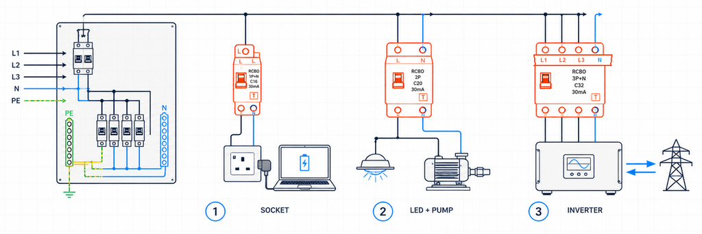
Три разные конечные цепи, требующие выбора RCBO на основе их фактической нагрузки и конфигурации проводниковЭти примеры иллюстративны, а не являются записями завершённых проектов JUTRION. Их цель — показать, как один параметр меняется из-за изменения цепи.
Проектный файл 1: Офисная розеточная цепь
Первая цепь питает общие розетки в офисе с напряжением 230 В. Сегодня подключённое оборудование включает ноутбуки, мониторы, зарядные устройства и принтер. Завтра пользователи могут подключить другие электронные приборы. Поэтому проектировщик не может гарантировать, что цепь останется простой синусоидальной нагрузкой переменного тока.
Type A — обоснованная отправная точка
Тип AC реагирует на синусоидальный переменный остаточный ток. Тип A также реагирует на пульсирующий постоянный остаточный ток. Современная однофазная электроника обычно содержит выпрямители и импульсные источники питания, поэтому тип A обычно является более практичной отправной точкой для неуточнённой розеточной цепи.
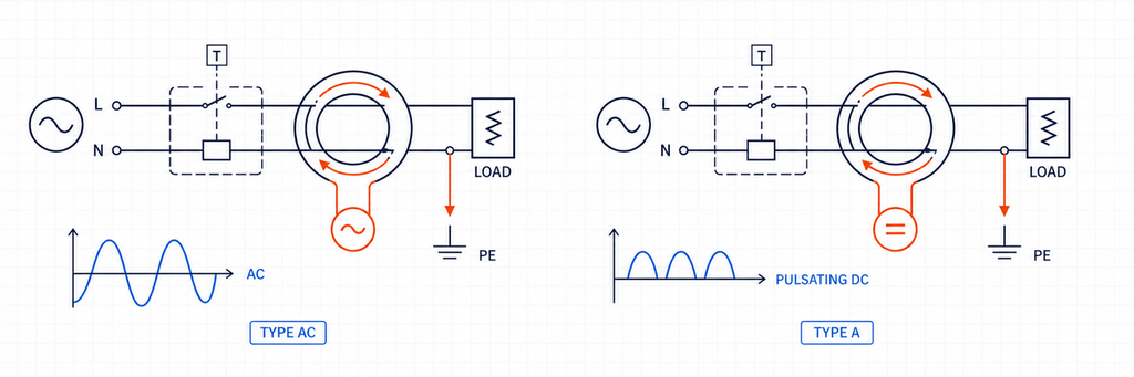
Сравнение формы волны дифференциального тока RCBO Type AC и Type AТип A не является универсальной заменой для всех типов УЗО. Оборудование, способное создавать гладкий постоянный ток или определённые смешанные частоты остаточного тока, может требовать тип F, тип B или другую заявленную схему. Однако для общей офисной розеточной цепи тип A более реалистично соответствует нагрузке, чем тип AC.
Почему 30 mA и 20 A отвечают на разные вопросы
Спецификация офиса предлагает номинал остаточного тока 30 mA для дополнительной защиты согласно применимым правилам монтажа. Это значение IΔn описывает функцию остаточного тока. Оно не описывает ток нагрузки, который может проходить по цепи.
Предположим, что рассчитанный проектный ток составляет 17,2 A, а установленный кабель имеет скорректированную пропускную способность 24 A. Устройство на 20 A удовлетворяет исходному соотношению защиты проводника:
Ib ≤ In ≤ Iz
17,2 A ≤ 20 A ≤ 24 A
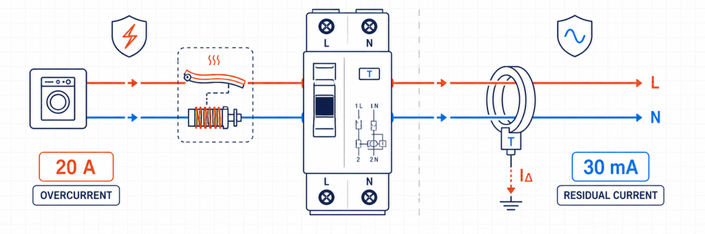
Сравнение защиты от сверхтока RCBO 20 ампер с защитой от дифференциального тока 30 миллиамперЗдесь Ib — проектный ток, In — номинальный ток RCBO, Iz — скорректированная пропускная способность кабеля. Температура окружающей среды, группировка, изоляция, способ монтажа, гармоники и национальные нормы уже учтены в Iz. Выбор 25 A, как следующего каталожного размера, превысил бы заявленную пропускную способность кабеля.
Индивидуальные RCBO защищают как цепь, так и людей
Если несколько офисных цепей объединены одним RCCB, утечки из их электронных фильтров накапливаются на общем устройстве. Одно событие замыкания на землю может также отключить все последующие MCB. Индивидуальные RCBO разделяют утечки по цепям и обычно содержат защиту по остаточному току для поражённой ветви. Это облегчает поиск неисправностей и снижает ненужные отключения.
Архитектура не устраняет планирование утечки. Нормальный ток защитного проводника всё ещё нуждается в запасе ниже порога устройства, особенно там, где подключено много ИТ-источников питания или длинных кабелей.
Результат для офиса
230 В AC, 1P+N RCBO, 20 A, тип A, 30 mA, кривая B или C с учётом пусковых токов и проверки неисправностей, отключающая способность выше измеренного/расчётного уровня короткого замыкания на щите, совместим с заявленной шиной распределительного щита.
Кривая и отключающая способность остаются открытыми, поскольку ни одну из них нельзя выбрать только по “офисным розеткам”.
Проектный файл 2: Светодиодное освещение рядом с малым насосом
Вторая панель содержит две отходящие цепи с похожим нормальным током. Одна питает группу светодиодных драйверов; другая питает малый насос прямого пуска. Обе могут создавать кратковременный пик тока при включении, но источник и длительность этого пика различаются.
Кривая B versus кривая C — решение по пусковому току и пути повреждения
Для распространённых характеристик миниатюрных автоматических выключателей IEC кривая B обычно имеет мгновенный диапазон срабатывания около 3–5 раз In, тогда как кривая C — около 5–10 раз In. Кривая D, часто около 10–20 раз In, предназначена для более высоких пусковых нагрузок, которые были специально спроектированы. Точное срабатывание необходимо проверять по применимым данным изделия.
RCBO с кривой C может выдерживать больший кратковременный пусковой ток до срабатывания его магнитного элемента. Это не делает его лучшим выбором общего назначения. Более высокий порог также означает, что цепь должна обеспечить больший ток повреждения для гарантии мгновенного отключения.
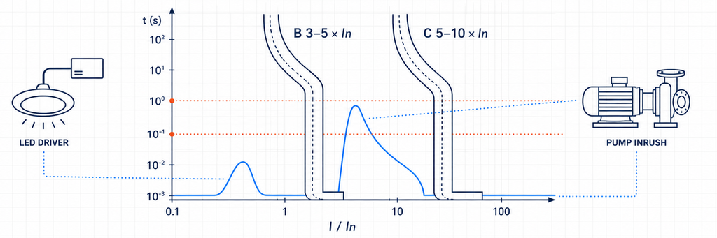
Сравнение мгновенных диапазонов срабатывания RCBO с кривой B и кривой C с пусковым током светодиодного драйвера и насоса| Доказательства из цепи | Что это предполагает | Что необходимо проверить далее |
|---|---|---|
| Низкий или контролируемый пусковой пик | Кривая B может оставаться подходящей | Кривая производителя и нормальные коммутационные события |
| Короткий, повторяемый пик выше области магнитного расцепления B | Рассмотреть кривую C | Условия контура повреждения/отключения и защита кабеля |
| Очень высокий бросок тока трансформатора или двигателя | Проектное решение C/D или другой метод пуска | Доступный ток повреждения, координация и защита оборудования |
| Срабатывание происходит после работы в течение нескольких минут | Вероятно, тепловая перегрузка, а не бросок тока | Ток нагрузки, температура корпуса, клеммы и кабель |
| Индикация срабатывания показывает работу по дифференциальному току | Замена B на C не решит проблему | Утечки, изоляция, влажность, прокладка нейтрали и тип УЗО |
Это различие предотвращает распространённую ошибку диагностики. RCBO с характеристикой B и C и одинаковой маркировкой 30 mA имеют одинаковую номинальную чувствительность по остаточному току. Буква кривой относится к секции защиты от перегрузки по току; она не делает RCBO более устойчивым к утечкам на землю.
Светодиодные драйверы и насосные двигатели также меняют требования к типу УЗО.
Драйверы светодиодов содержат электронику, поэтому тип A является разумной базовой линией. Обычная однофазная цепь двигателя также может включать электронный контроллер, устройство плавного пуска или регулируемый привод. Как только вводится силовая электроника, инструкции оборудования — а не слово “двигатель” — определяют, остаётся ли тип A подходящим или требуется поведение типа F/B.
Два результата для цепи
После проверки умеренного броска тока драйвера светодиодов и достаточного тока повреждения цепь освещения может быть выполнена как:
230 В AC, 1P+N, 16 A, Тип A, 30 mA, кривая B, 6 kA при условии, что проверенный расчетный ток короткого замыкания ниже этого значения.
Если запись пуска насоса превышает область кривой B, но цепь удовлетворяет требованиям отключения по кривой C, цепь насоса может быть выполнена как:
230 В AC, 1P+N или 2P по требованию, 16 A, Тип A (или тип, указанный в оборудовании), 30 mA при необходимости, кривая C, отключающая способность, соответствующая уровню короткого замыкания на щите.
Различие заключалось не в “освещение против двигателя” по обозначению. Оно заключалось в измеренном или заявленном поведении при пуске, форме кривой дифференциального тока и пути повреждения.
Проектный файл 3: трёхфазная цепь с инверторным питанием
Третий проект подключает трёхфазную силовую электронную систему. Она может импортировать мощность, экспортировать мощность или работать иначе, когда активен резервный источник. Каталожный ярлык, такой как “четырёхполюсный, тип B”, небезопасен, поскольку конструкция преобразователя и топология питания ещё не установлены.
Пусть документация преобразователя определяет тип дифференциального тока
Тип F расширяет поведение Типа A для определённых условий смешанной частоты, связанных с выбранными однофазными инверторными нагрузками. Тип B охватывает более широкий диапазон остаточного тока, включая плавный постоянный ток в рамках своих характеристик. Некоторые зарядные устройства для электромобилей и инверторы имеют мониторинг остаточного постоянного тока; другие требуют специального устройства на входе.
Выбор не может быть сделан только по категории продукта. Подтвердите:
- форму кривой дифференциального тока, которую может создавать оборудование;
- наличие внутреннего обнаружения остаточного постоянного тока;
- точные требования к УЗО/RCBO на входе согласно инструкциям к оборудованию;
- координацию с любым устройством дифференциального тока выше по цепи;
- национальные правила для данного применения.
Не путайте RCBO Типа B с RCBO с кривой B. Тип B описывает способность обнаружения дифференциального тока. Кривая B описывает мгновенную реакцию на сверхток. Продукт может быть типа B с кривой C.
Полюса соответствуют проводникам, а не названию нагрузки
Трёхфазная трёхпроводная нагрузка без нейтрали может использовать схему 3P. Трёхфазная четырёхпроводная система с нейтралью требует 3P+N или 4P в соответствии с продуктом, системой и правилами монтажа. В технических данных должно быть указано, коммутируется ли нейтраль, является ли она глухой или защищённой от сверхтоков.
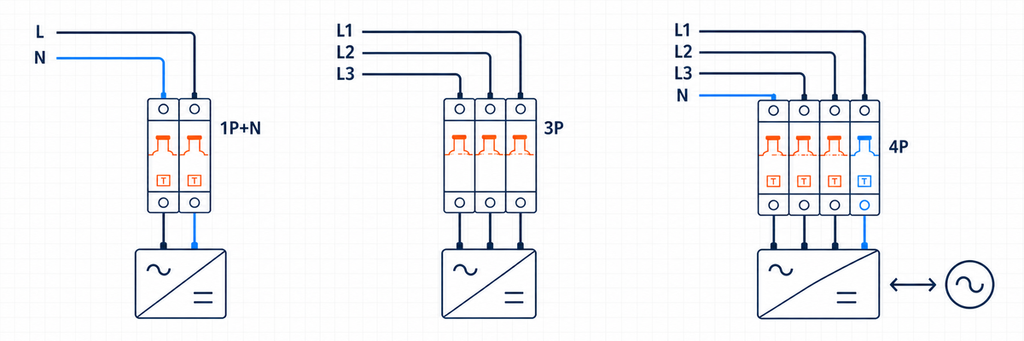
RCBO с конфигурациями полюсов 1P+N, 3P и 4P для цепей с инверторным питанием| Схема | Вероятная система | Требуемое подтверждение |
|---|---|---|
| 1P+N | Однофазная линия и нейтраль | Коммутация нейтрали, направление линия/нагрузка и положение шины |
| 2P | Однофазный с двухполюсным отключением | Какие полюса коммутируются и защищаются от сверхтока |
| 3P | Трёхфазный без нейтрали | Нет эксплуатационной или измерительной необходимости в нейтрали |
| 3P+N | Трёхфазный с нейтралью | Поведение коммутации/защиты нейтрали |
| 4P | Трёхфазный, четырёхпроводный с заявленным четырёхполюсным режимом работы | Одновременная работа и совместимость системы |
Каждый проводник, требуемый схемой измерения дифференциального тока, должен соответствовать схеме производителя. Заимствованная или шунтированная нейтраль создаёт дисбаланс и может вызвать срабатывание устройства даже при исправных нагрузках.
Обратная мощность требует заявленного двунаправленного устройства
Солнечные панели, аккумуляторы и оборудование vehicle-to-grid могут подавать питание в цепь в направлении, противоположном обычной нагрузке. Ручной переключатель не доказывает пригодность для двунаправленной работы. Проверьте допустимое направление подачи питания, ориентацию клемм, характеристики короткого замыкания в каждом направлении, поведение нейтрали и утверждённую систему распределительного щита.
RCBO — лишь одна часть этой цепи защиты. Он не заменяет обязательную изоляцию, функции антиостровного режима, защиту от перенапряжений или идентификацию безопасного источника.
Результат для цепи инвертора
400 В AC, 3P/3P+N/4P в зависимости от фактической системы проводников, тип остаточного тока согласно требованиям производителя преобразователя, чувствительность согласно правилам применения, кривая C/D только после запуска и проверки неисправности, заявленное двунаправленное использование при возможности обратной мощности, и отключающая способность выше проектного уровня короткого замыкания.
Это спецификация длиннее, потому что система содержит больше интерфейсов. Сокращение до «4P C32 30 mA» отбросит решения, наиболее влияющие на совместимость.
Дешифратор номиналов: что доказывает каждая маркировка
Три проектных файла теперь можно свести к одной таблице декодирования. Каждый номинал закрывает отдельный риск; ни одно отдельное значение не может заменить другое.
| Область применения RCBO | Инженерное значение | Проектное подтверждение | Отказ при игнорировании |
|---|---|---|---|
| Номинальное напряжение/частота | Условия питания для заявленного режима работы | Системные чертежи и данные оборудования | Неправильная работа или недействительный номинал |
| In (А) | Номинальный ток секции защиты от сверхтока | Ib, скорректированный Iz и режим нагрузки | Срабатывания от перегрузки или незащищённый кабель |
| Кривая B/C/D | Мгновенная магнитная характеристика | Данные по пусковому току и току КЗ | Ложные срабатывания при пуске или недостаточное отключение при КЗ |
| Тип AC/A/F/B | Возможности по форме волны дифференциального тока | Топология нагрузки и инструкции производителя | Неспособность правильно реагировать на возможную форму волны |
| IΔn (мА) | Чувствительность дифференциального тока | Цель защиты и правило монтажа | Неправильный уровень защиты или плохая непрерывность |
| Полюса/нейтраль | Проводники, измеряемые, коммутируемые и защищаемые | Однолинейная схема и система заземления | Неправильная изоляция, измерение или работа нейтрали |
| Отключающая способность (кА) | Максимальный заявленный режим прерывания короткого замыкания | Ожидаемый ток короткого замыкания | Устройство используется за пределами его испытанной отключающей способности |
| Интерфейс направления/платы | Ориентация питания и физическая совместимость | Текущий лист данных и декларация платы | Неправильная установка, несоответствие шинопровода или проблема обратного питания |
IEC 61009-1:2024 устанавливает требования к продукции и методы испытаний для RCBO бытового и аналогичного назначения в рамках заявленной области применения. Он не заменяет национальный код установки. Соответствие продукции отвечает на вопрос, соответствует ли RCBO заявленным требованиям к продукции; соответствие установки отвечает на вопрос, правильно ли это устройство применено в цепи.
Почему 10, 30, 100 и 300 mA не являются классами качества
Меньшее IΔn означает более высокую чувствительность, но «более чувствительный» не значит «лучший для каждой позиции». Устройства на 10 мА могут быть выбраны для специальных локальных или повышенных требований по чувствительности. 30 мА широко используется для дополнительной защиты на конечных цепях. Значения 100 и 300 мА применяются для выбранных устройств на входе, оборудования или в целях пожарной безопасности.
Устройство на 100 или 300 мА на входе не заменяет защиту 30 мА на выходе там, где она требуется. Напротив, установка мгновенной защиты 30 мА и на входе, и на выходе может нарушить селективность, так как оба устройства реагируют на одинаковое несимметричное остаточное напряжение.
Там, где используется вышестоящая защита от остаточного тока, координируйте как порог срабатывания, так и время срабатывания. Селективная/с выдержкой времени функция должна находиться на уровне, допускаемом проектом установки; она не должна задерживать защитную функцию конечной цепи, которая должна срабатывать быстро.
6 кА или 10 кА — это решение для конкретного места
Отключающая способность должна быть не меньше ожидаемого тока короткого замыкания в точке установки RCBO при его заявленных условиях. Плата рядом с трансформатором может иметь более высокий уровень тока повреждения, чем удалённая конечная цепь, даже если удалённое здание физически больше.
Используйте расчёт, измерение или надёжную проектную запись уровня тока повреждения. Если предлагается вышестоящая резервная защита, используйте испытанную или заявленную комбинацию производителя. Вышестоящий автоматический выключатель с большим номиналом отключения не передаёт этот номинал нижестоящему RCBO автоматически.
Резервная защита и селективность — это также разные вещи. Комбинация может безопасно прервать большой ток повреждения, при этом оба устройства сработают. Если для непрерывности требуется отключение только нижестоящей цепи, получите доказательство селективности для соответствующего диапазона токов.
Превратите проектные данные в описание для заказа
Перед выбором модели соберите одну краткую проектную запись:
- страна/рынок и применимые требования к установке;
- напряжение системы, частота и схема заземления;
- однофазные или трёхфазные проводники, включая нейтраль;
- описание нагрузки, топология электронного преобразователя и пусковой ток;
- расчётный ток и скорректированная пропускная способность кабеля;
- требуемая цель защиты от остаточного тока;
- ожидаемый ток короткого замыкания у платы;
- направление потока мощности во всех режимах работы;
- модель потребительского щита/распределительной платы, шинопровод и доступная ширина модуля;
- требования к клеммам, окружающей среде, индикации и принадлежностям.
Затем запишите спецификацию одной строкой:
[voltage/frequency], [poles and neutral arrangement], [In], [curve], [Type AC/A/F/B], [IΔn], [breaking capacity], [supply direction], [product standard/market approval], [board and busbar interface].
Эта строка полезнее, чем просить поставщика о “хорошем RCBO”. Она даёт инженерным и закупочным командам одну и ту же ссылку и выявляет недостающую информацию до утверждения образцов или производства.
Проверьте выбранный RCBO в фактической плате
Технически правильный набор номиналов всё равно может не подойти на уровне сборочного интерфейса. Прежде чем дистрибьютор примет заменяющий ряд или OEM выпустит потребительский щит, выбранный RCBO следует проверить в предполагаемом корпусе с предполагаемым шинопроводом, проводниками и принадлежностями.
Механическая совместимость и совместимость по электромонтажу
Подтвердите ширину модуля, зацепление с DIN-рейкой, положение зубьев шинопровода, расположение нейтрали и доступ к клеммам. Устройство, описанное как 1P+N, может использовать свободный нейтральный провод, нейтральную клемму с определённой стороны или другой шаг шинопровода по сравнению с другим устройством 1P+N. Похожие передние размеры не доказывают взаимозаменяемость.
Проверьте допустимый материал проводников, жёсткое/гибкое сечение и требования к наконечникам. Подготовьте проводники в соответствии с заявленными требованиями и примените указанный момент затяжки клемм. Слабое соединение может создавать нагрев, не превышая ток нагрузки цепи, тогда как чрезмерный момент затяжки может повредить клемму или проводник.
Функциональное подтверждение
При вводе в эксплуатацию следует различать две системы расцепления. Там, где устройство обеспечивает отдельную индикацию, зафиксируйте, сообщается ли результат тестовой операции как срабатывание от остаточного тока или от сверхтока. Проверьте функцию тестовой кнопки при условиях питания, указанных производителем, затем выполните испытания при установке, требуемые применимыми правилами. Тестовая кнопка проверяет внутренний функциональный путь; она не измеряет полную петлю замыкания на землю, состояние изоляции или каждое требование ко времени срабатывания.
Для цепей с множеством электронных нагрузок зафиксируйте нормальный ток нагрузки, пусковой пик и установившийся ток утечки после ввода в эксплуатацию. Эти три значения создают базовый уровень. Если срабатывания появятся через месяцы, техническое обслуживание сможет сравнить новые данные с исходным состоянием, а не заменять устройства методом проб и ошибок.
Температура и группировка
Несколько нагруженных модульных устройств, установленных рядом, могут работать в более тёплой локальной среде, чем предполагает температура помещения. Вентиляция корпуса, соседние тепловыделяющие компоненты, размер проводников и продолжительная нагрузка — всё это влияет на температуру. Применяйте инструкции производителя по снижению номинала или расстоянию там, где это relevant; не реагируйте на тепловое расцепление увеличением номинала по току без повторной проверки защиты кабеля.
Контроль партий и документации
Для производителя OEM или дистрибьютора зафиксируйте утверждённые атрибуты в спецификации: точная модель, кривая, тип дифференциального тока, IΔn, число полюсов, отключающая способность, расположение выводов, одобрение и совместимые аксессуары. Замена, совпадающая только по току и ширине, может незаметно изменить тип формы сигнала или поведение нейтрали.
Сохраняйте актуальный технический паспорт, декларационные/сертификационные документы, требуемые целевым рынком, схему подключения и идентификацию партии вместе с записью об утверждённом образце. Это превращает выбор в воспроизводимый производственный контроль, а не в разовый инженерный разговор.
Разделяйте соответствие продукции и соответствие при монтаже
Маркировка IEC важна, но она не определяет, где и как можно устанавливать RCBO. IEC 61009-1:2024 определяет общие требования и испытания для RCBO для бытового и аналогичного применения в рамках своей области действия. Национальные правила монтажа, местные нормативы, проектные спецификации и органы надзора определяют условия установки.
| Вопрос | Откуда берётся ответ | Пример |
|---|---|---|
| Был ли RCBO оценён как продукт? | Стандарт на продукцию, сертификация и документация производителя | Объявленное напряжение, ток, IΔn, тип и короткозамыкательная способность |
| Требуется ли защита от остаточного тока здесь? | Национальные правила установки и проектирования | Розетка, наружная, для влажных помещений или цепь специального оборудования |
| Какой тип остаточного тока разрешен? | Правила установки плюс инструкции по оборудованию | Ограничение на тип AC или требование, созданное преобразовательным оборудованием |
| Отключится ли цепь вовремя? | Расчет/тест установки и характеристики устройства | Условия замыкания для выбранной кривой B/C/D |
| Подойдет ли RCBO для этой панели? | Декларации системы панели и производителя устройства | Шина, клеммы, нейтральное положение и рейтинг корпуса |
Это различие имеет значение в экспортных проектах. Конфигурация продукта, принятая на одном рынке, может требовать другого типа остаточного тока, расположения полюсов, знака одобрения или системы распределительной панели на другом. Не преобразуйте национальное правило в универсальное утверждение IEC и не предполагайте, что сертификат компонента одобряет завершенную панель.
Категория Руководство по выбору RCD BEAMA является полезным авторитетным источником для волновых и прикладных обоснований, особенно в отношении современных электронных нагрузок. Его региональные ссылки по установке все еще необходимо применять в рамках своей юрисдикции. Для другого рынка используйте соответствующие национальные правила и инструкции по оборудованию.
Где подходит RCBO — и где не подходит
RCBO сочетает защиту от остаточного тока с защитой от перегрузки и короткого замыкания. RCCB обычно требует согласованной защиты от перегрузки, в то время как MCB не обеспечивает защиту от остаточного тока. Архитектура RCBO на каждую цепь часто улучшает непрерывность и изоляцию от неисправностей, но она все равно должна согласовываться с защитой на вышестоящем уровне и распределительной панелью.
RCBO обычно не распознает опасные сигнатуры дуги. Если смягчение дуговых замыканий является частью проекта, используйте руководство JUTRION AFDD для определения требуемых функций защиты. RCBO также не заменяют SPD, изоляторы или специфическую защиту оборудования только потому, что несколько функций размещены в одном корпусе.
Выберите задачу защиты перед номером каталога
Офисная цепь начиналась с непредсказуемых электронных нагрузок, поэтому выбор контролировался УЗО типа A и индивидуальной защитой с током срабатывания 30 мА. Цепи освещения и насосов начинались с учётом пусковых токов, поэтому выбор кривой B или C зависел как от пускового, так и от аварийного тока. Цепь инвертора учитывала форму сигнала, топологию проводников и обратную мощность, поэтому инструкции к оборудованию и разрешение на двунаправленное использование имели значение выше ампеража.
Это правило выбора, которое можно передать: определить неисправность, которую должен обнаружить RCBO, подтвердить кабель и путь неисправности, затем завершить физический интерфейс. Правильный номер каталога является результатом этого процесса, а не отправной точкой.
JUTRION предлагает RCBO для однофазного и трёхфазного распределения с несколькими комбинациями полюсов, тока, чувствительности, типа формы волны, кривой и короткозамыкательной способности. Поделитесь вышеуказанным проектом при запросе поддержки выбора, чтобы предложенная модель могла быть проверена на соответствие реальной цепи.
Часто задаваемые вопросы
Должен ли я выбрать RCBO типа A или типа AC?
Тип AC обнаруживает синусоидальный переменный остаточный ток, тогда как Тип A также обнаруживает пульсирующий постоянный остаточный ток. Поскольку многие современные приборы содержат выпрямители и импульсные источники питания, Тип A часто является более практичной отправной точкой для общих розеточных, осветительных и бытовых цепей. Окончательный выбор должен соответствовать инструкциям к подключённому оборудованию и применимым правилам монтажа.
Является ли RCBO на 30 mA всегда правильным выбором?
Нет. Значение остаточного тока 30 mA обычно используется там, где требуется дополнительная защита, но это не универсальное значение для каждой цепи. Необходимо проверить правила применения, ожидаемые постоянные утечки, селективность на входе и требования оборудования. Значение 30 mA также не определяет номинальный ток нагрузки RCBO.
В чем разница между RCBO типа B и RCBO с кривой B?
Они описывают разные функции. Тип B указывает на способность обнаружения остаточного тока, включая плавный постоянный ток в пределах заявленных характеристик устройства. Кривая B определяет мгновенный диапазон срабатывания секции защиты от перегрузки. Таким образом, RCBO может иметь поведение остаточного тока Типа B и характеристику перегрузки по кривой C.
Когда мне следует выбрать RCBO с кривой C вместо кривой B?
Рассмотрите кривую C, когда проверенный пусковой ток от оборудования, такого как двигатели, трансформаторы или группы драйверов LED, может войти в магнитный рабочий диапазон кривой B. Кривая C не является автоматическим решением для ложного срабатывания: цепь все равно должна обеспечивать достаточный ток короткого замыкания для требуемого времени отключения, и индикация срабатывания должна сначала подтвердить, что событие является перегрузкой, а не остаточным током.
Нужен ли мне RCBO 1P+N, 2P, 3P или 4P?
Выберите конфигурацию полюсов в зависимости от фактических проводников питания и требуемого метода отключения. Однофазная цепь с линией и нейтралью может использовать 1P+N или 2P в зависимости от продукта и проектирования установки. Трехфазные цепи могут требовать 3P, 3P+N или 4P в зависимости от наличия нейтрали и того, как она должна быть переключена и обнаружена. Всегда следуйте схеме подключения производителя.
Могу ли я использовать стандартный RCBO типа A с инвертором?
Только если производитель инвертора и применимые правила установки это допускают. Электронное оборудование может требовать тип A, тип F, тип B или конфигурацию, согласованную с встроенным мониторингом остаточного постоянного тока. Также проверьте конфигурацию полюсов, обработку нейтрали, допустимое направление питания и заявленную двунаправленную работу, когда энергия может возвращаться в сеть.
Технические ссылки
