

Как подобрать ATS для гибридных солнечных инверторов: переключение при подключении к сети vs. автономное резервное питание
Для выбора ATS для гибридного солнечного инвертора сначала определите, что именно будет переключать выключатель. Не выбирайте его только по киловаттам PV-массива. В точке установки сравните максимальный ток прохождения через сеть, максимальный резервный выходной ток инвертора и расчетный ток панели передаваемой нагрузки. Используйте наибольший ток, который законно может проходить через ATS, затем проверьте расположение полюсов, ток короткого замыкания, категорию использования, логику переключения и совместимость с утверждённой резервной архитектурой инвертора.
Это различие важно, потому что «сетевой», «гибридный» и «автономный» описывают разные электрические режимы. Обычный сетевой PV-инвертор обычно прекращает подачу питания при длительном отключении сети. Гибридный инвертор может содержать внутреннее реле переключения и выделенный резервный выход. Автономный инвертор может формировать собственную шину AC и использовать сеть или генератор только как альтернативный вход. Установка одного и того же универсального ATS во всех трёх системах может привести к ложным срабатываниям, неработающим резервным нагрузкам, конфликтующим командам переключения или небезопасному параллельному пути.
Это руководство объясняет, как определить правильные границы ATS, рассчитать ток и указать схему переключения для каждой архитектуры. Оно дополняет наше общее руководство по подбору автоматического переключателя резерва, при этом сосредоточиваясь конкретно на гибридных солнечных системах и системах резервного питания от батарей.
Краткий ответ: какой номинал должен определять размер ATS?
Контролирующий ток зависит от расположения ATS:
| Расположение ATS | Выбираемые источники | Основа для расчёта тока | Распространённая ошибка |
|---|---|---|---|
| Перед входом AC инвертора | Сеть и генератор | Максимально допустимый ток входа AC или прохождения, требование к передаваемой нагрузке и ограничение источника | Подбор только по выходной мощности инвертора в кВт |
| После резервного выхода | Резервный выход инвертора и байпас сети | Более высокий реальный ток, подаваемый на панель резервных нагрузок | Использование мощности PV-массива в кВт вместо тока резервной панели |
| Граница ввода на всё здание | Коммунальный источник и источник намеренной островной работы | Расчёт ввода/нагрузки плюс одобренный номинал резервного интерфейса | Добавление универсального ATS в систему, требующую сертифицированного интерфейса резервного питания |
| Вне сети AC-шина | Инвертор и генератор или байпас коммунальной сети | Максимальный ток переключаемой нагрузки и длительные пределы обоих источников | Допущение подключения источников двумя независимыми контроллерами без согласованной блокировки |
Выбранный размер корпуса не должен быть меньше максимального расчетного тока через выключатель. Однако одних ампер недостаточно для полной спецификации. Итоговый ATS также должен соответствовать напряжению системы, количеству фаз, схеме нейтрали и заземления, ожидаемому уровню короткого замыкания, способу переключения и применимым правилам монтажа.
Начинайте с архитектуры, а не с каталога ATS
Перед расчётом тока проведите одну линию от каждого возможного источника к нагрузкам. Отметьте точку подключения коммунальной сети, сетевой вход инвертора, резервный выход инвертора, батарею, генератор, панель ответственных нагрузок и каждое устройство, способное размыкать или замыкать путь источника. Если переключающий механизм, контроллер, контроль источников и блокировка всё ещё незнакомы, изучите как работает автоматический переключатель резерва и как его выбрать прежде чем окончательно оформлять однолинейную схему. Схема должна делать невозможным одновременное подключение коммунальной сети и несинхронизированного островного источника.
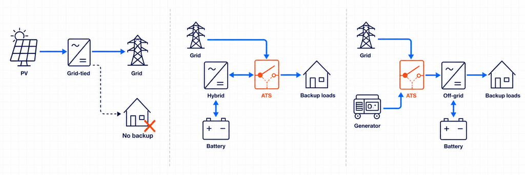
Министерство энергетики США различает инверторы, следующие за сетью (grid-following), которые требуют функционирующей сети, и инверторы, формирующие сеть (grid-forming), способные работать при отсутствии сети. Также отмечается, что обычные сетевые инверторы отключаются при крупных или длительных нарушениях сети. Поэтому ATS не может превратить стандартный сетевой инвертор в резервный источник. Для резервного питания требуется инвертор и схема изоляции, специально разработанные для работы в режиме острова.
Архитектура 1: Традиционный сетевой PV-инвертор без резервирования
Традиционный сетевой PV-инвертор работает параллельно с электросетью и экспортирует или компенсирует энергию при нормальной работе сети. При отключении питания защита от островного режима отключает инвертор. Стабильного альтернативного источника переменного тока для выбора ATS нет.
В этой архитектуре установка ATS между сетью и домом не обеспечивает продолжение работы PV-системы. Инвертору по-прежнему требуется действующая сетевая опорная точка, и ему не разрешено подавать питание в изолированную цепь, если он не предназначен и не сертифицирован для формирования острова. Если требуется резервное питание при отключении, архитектура системы должна измениться: обычно добавляются совместимый аккумулятор, функция формирования сети инвертором, интерфейс резервирования и граница критической нагрузки.
Архитектура 2: Гибридный инвертор с внутренним переключающим устройством
Многие гибридные инверторы имеют отдельные клеммы для сети и резервного питания. Внутри устройство переключения изолирует сеть и подает резервный выход от аккумулятора и инвертора при отключении. В этом случае документация инвертора, а не универсальная схема, определяет допустимую схему нейтрали, защитные устройства, размер резервной панели, последовательность повторного подключения и разрешение на использование внешнего ATS.
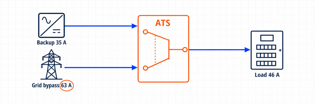
Дополнительный ATS может иметь законное назначение. Например, он может обходить неисправный инвертор и напрямую подключать панель критической нагрузки к сети. В такой схеме ATS не создает солнечный остров, а выбирает между резервным выходом инвертора и обходом сети. Поэтому номинал тока ATS должен покрывать максимальный ток на любом из этих путей.
Некоторые гибридные платформы используют отдельный системный контроллер или интерфейс резервирования, уже содержащий функцию переключения. Замена или дублирование этой функции универсальным ATS может нарушить мониторинг системы, управление нейтралью, логику защиты от островного режима или сертификацию производителя. Рассматривайте «внутренний переключатель», «интерфейс резервирования» и «внешний обходной ATS» как три разные компоненты, пока утвержденная однолинейная схема не докажет обратное.
Архитектура 3: Вне сети или формирующий сеть инвертор с альтернативным входом переменного тока
Вне сетевой инвертор обычно устанавливает напряжение и частоту для локальной AC-шины. К входу переменного тока может быть подключена сеть или генератор, чтобы инвертор/зарядное устройство мог переключать нагрузки, заряжать аккумулятор или поддерживать питание. Многие инвертор/зарядные устройства уже содержат внутреннее реле переключения. Если в конструкции используется внешний ATS, он может выбирать между сетью и генератором на входе инвертора или между выходом инвертора и обходным источником на панели нагрузки.
Эти две позиции не являются взаимозаменяемыми. ATS на стороне входа видит ток, принимаемый и пропускаемый инвертором/зарядным устройством. Обходной ATS на стороне выхода видит ток, потребляемый переключёнными нагрузками. Контроллер на стороне входа также может нуждаться в контактах запуска/остановки генератора, времени прогрева, окнах допустимого напряжения и частоты и последовательности охлаждения. Устройство на стороне выхода должно избегать обратной подачи на выход инвертора, когда обход активен, если только конструкция производителя явно это не допускает.
Четыре значения тока, которые необходимо зафиксировать
Надёжный лист подбора фиксирует четыре значения тока, а не одно число солнечной мощности.
Расчётный ток переключённых нагрузок
Это ток, требуемый нагрузками, подключёнными ниже ATS. Он не является автоматически номиналом главного ввода и не является автоматически номиналом инвертора. Переключатель для всего здания может нести расчётную нагрузку здания. ATS для ответственных нагрузок может нести только холодильное оборудование, освещение, системы управления, связи, выбранные розетки и другие приоритетные цепи.
Используйте проектный расчёт нагрузок и применимые электротехнические нормы. Учитывайте продолжительные нагрузки, двигатели, трансформаторы, компрессоры и одновременную работу. Если сброс нагрузки является частью проекта, задокументируйте, какие нагрузки отключаются, прежде чем использовать уменьшенное значение.
Максимальный выходной ток резервного питания инвертора
Читайте технический паспорт или руководство по установке инвертора. Предпочитайте заявленный максимальный непрерывный ток резервного выхода вместо расчета по маркетинговой мощности. Если доступна только кажущаяся мощность, базовые расчеты переменного тока следующие:
Однофазная сеть: I = S ÷ V
Трёхфазная сеть: I = S ÷ (√3 × V)
Для однофазного выхода 10 kVA, 230 V идеальный ток примерно 43,5 A. Для трехфазного выхода 30 kVA, 400 V — примерно 43,3 A на фазу. Эти значения — отправная точка, а не разрешение игнорировать пределы тока производителя, кривую перегрузки, пределы дисбаланса фаз или снижение номинала по температуре.
Ток сквозного прохождения или байпаса сети
Часто это контролирующее значение. Гибридный инвертор с резервной мощностью 8 kW может пропускать больший ток сети через внутреннее реле при наличии сети. Аналогично, внешний обход может питать всю панель критической нагрузки напрямую от сети.
Если через ATS в сетевом режиме может проходить 63 A, выбирать ATS на 40 A из-за того, что инвертор выдает только 8 kW, неправильно. Контакты и клеммы переключателя должны выдерживать ток 63 A. Запишите максимальный ток входа/пропуска инвертора, номинал обходного выключателя и расчет нагрузки вниз по цепи, затем используйте наиболее ограничивающий согласованный дизайн.
Максимальный ток, допустимый для каждого источника и защитного устройства
Фидер электросети, автоматический выключатель генератора, выходная защита инвертора, проводники и главное устройство распределительного щита устанавливают границы. ATS не создаёт дополнительную мощность источника, и его номинальный ток сам по себе не защищает кабели. Переключатель класса PC обычно полагается на согласованную вышестоящую защиту от сверхтока; конфигурация класса CB интегрирует функции автоматического выключателя. Выбирайте и проверяйте всю защитную цепочку.
Практический метод подбора ATS для гибридных инверторов
- Убедитесь, что инвертор может формировать островной режим. Если это только PV и сетевой инвертор, остановитесь: нет действительного резервного источника для ATS.
- Используйте одобренную производителем архитектуру. Определите требуемый интерфейс резервного питания, внутреннее реле переключения, совместимый внешний переключатель или разрешённую схему байпаса.
- Отметьте положение ATS. Укажите точно, какие два источника подключаются к Источнику I и Источнику II, и какая панель подключается к общему выходу.
- Определите переключаемые нагрузки. Используйте график критических нагрузок или расчёт потребности всего здания, а не суммируйте таблички приборов без разбора.
- Зафиксируйте выходной ток резервного питания. Используйте заявленный максимальный ток и отдельно отметьте возможность кратковременной перегрузки.
- Зафиксируйте ток сквозного прохождения или байпаса сети. Проверьте ограничение входного тока инвертора, номинал внутреннего реле, байпасный фидер и главное устройство панели.
- Выберите длительный ток. ATS должен пропускать максимальный возможный ток в месте его установки с учётом правил кодекса, снижения номинальных характеристик, температуры корпуса и инструкций производителя.
- Выполните проверки, не связанные с силой тока. Проверьте напряжение, частоту, фазы, полюса, обработку нейтрали, номинал короткого замыкания, категорию применения, время переключения, датчики, напряжение управления и блокировку.
- Проверьте каждое рабочее состояние. Рассмотрите нормальную работу от сети, отказ сети, отказ инвертора, разряженную батарею, работу генератора, байпас для обслуживания и возврат сети.
Пример расчета: 8 kW гибридный инвертор с обходом сети
Рассмотрим иллюстративную однофазную систему 230 V со следующими параметрами:
- Резервная мощность гибридного инвертора: 8 kVA непрерывно
- Заявленный максимальный ток резервного выхода: 35 A
- Допустимый ток пропуска сети: 63 A
- Расчетный ток панели критической нагрузки: 46 A при наличии сети
- Ограничение управления нагрузкой в резервном режиме: 32 A
- Положение внешнего ATS: выход резервного питания инвертора против прямого байпаса сети
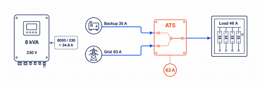
Приблизительный ток инвертора по кажущейся мощности: 8 000 ÷ 230 = 34,8 A, что соответствует заявленным 35 A выхода. Но ATS на 40 A не всегда подходит. В режиме обхода сети панель критической нагрузки может потреблять 46 A, а допустимый ток источника — до 63 A.
В этом месте выбор тока ATS контролируется путем обхода сети и перенесенной нагрузки, а не выходом инвертора 8 kVA. Класс 63 A может быть минимально практичным, если все проверки по непрерывной нагрузке, температуре, корпусу, клеммам и местным нормам разрешают. Корпус 80 A может быть выбран, если согласованный дизайн, снижение номинала по температуре, подключение проводников или стандарты проекта требуют большего запаса. Итог нельзя получить, исходя только из 8 kW.
Контроллер управления нагрузкой должен удерживать спрос в резервном режиме в пределах 35 A инвертора. Увеличение ATS до 63 A или 80 A не делает инвертор способным подавать 46 A при отключении. Это отдельное ограничение по управлению энергией и мощностью.
Переключение всего дома или переключение критических нагрузок?
Этот выбор изменяет как размер ATS, так и поведение системы. Схема переключения всего дома размещает границу резервного питания вокруг большей части или всей распределительной системы здания. Поэтому ATS и связанный интерфейс могут потребоваться для соответствия вводному устройству или расчётной потребности, даже если инвертор может подавать лишь часть этого тока. Успешное резервирование всего дома обычно зависит от автоматического управления нагрузкой, которое отключает нагрев воды, крупные системы кондиционирования, зарядку электромобилей, электрические плиты или другие нагрузки до перегрузки инвертора.
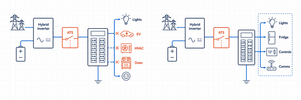
Схема критической нагрузки создает меньшую панель вниз по цепи. Только выбранные цепи переключаются на питание от инвертора. Это часто позволяет использовать ATS с меньшим номиналом тока, меньшие проводники и более предсказуемое время автономной работы аккумулятора. Также это делает видимым предел тока в резервном режиме: если панель содержит 32 A управляемой нагрузки, проектировщик может сверить это с заявленным выходом инвертора, а не надеяться, что пользователи не включат все нагрузки одновременно.
Используйте следующее решение:
- Выберите панель ответственных нагрузок когда выходная мощность инвертора существенно ниже мощности ввода, энергия батареи ограничена или надёжная приоритизация нагрузок важнее удобства.
- Рассмотрите передачу на весь дом когда одобренный контроллер системы поддерживает это, инвертор и батарея могут поддерживать требуемую нагрузку, и автоматическое отключение нагрузки задокументировано.
- Не уменьшайте ток ATS только потому, что программное обеспечение в режиме резервного копирования ограничивает инвертор. Если те же контакты несут полную нагрузку в режиме сети, подберите их для этого сетевого пути.
Для закупки укажите оба числа: “непрерывный ток ATS на установленной границе” и “максимально допустимая нагрузка в режиме резервного копирования”. Они отвечают на разные вопросы и предотвращают ситуацию, когда установщики рассматривают слишком большой выключатель как доказательство адекватной мощности инвертора.
Трехфазные гибридные инверторы требуют дополнительных проверок
Расчет тока для трехфазной системы предполагает сбалансированную кажущуюся мощность. Реальные резервные панели могут быть несбалансированными, а некоторые гибридные инверторы накладывают максимальный ток на фазу или максимальный допустимый дисбаланс фаз. Например, номинальный трехфазный инвертор 30 kVA, 400 V соответствует примерно 43,3 A на фазу:
I = 30 000 ÷ (1,732 × 400) = 43,3 A на фазу
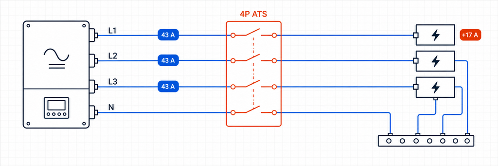
Этот результат не доказывает, что ATS на 50 A подходит. Проверьте, соответствует ли номинал пропускной способности сети 63 A, 80 A или другому значению; может ли резервный щит концентрировать однофазные нагрузки на одной фазе; и может ли инвертор запитывать все три фазы при островном режиме. Нагрузка 4 кВт, добавленная на одну фазу, примерно соответствует 17,4 A при 230 V, хотя суммарная трёхфазная мощность в кВА всё ещё кажется приемлемой.
Составьте фазовое расписание для основных нагрузок. По возможности распределяйте крупные однофазные нагрузки и проверяйте худшую фазу, а не только среднее значение. Если инвертор допускает 40 A на каждой фазе, а обход сети допускает 63 A, то ATS на границе резервного выхода/обхода сети всё равно может потребовать класс тока 63 A. Управление нагрузками в резервном режиме должно предотвращать превышение лимита инвертора на любой фазе.
Также подтвердите, что происходит, когда одна фаза выходит из строя. Некоторые контроллеры ATS переключаются при потере фазы; некоторые гибридные инверторы отключают весь выход; и некоторые приложения требуют определенной задержки, чтобы предотвратить работу на нестабильном сетевом питании. Мониторинг последовательности фаз может быть необходим для двигателей и вращающегося оборудования. Спецификация контроллера должна указывать поведение при пониженном напряжении, повышенном напряжении, потере фазы, последовательности фаз и частоте — не просто “автоматически”.”
Добавление генератора к гибридной солнечной системе
Генератор создает третий источник, даже если обычный ATS обычно выбирает только два. Поэтому проект требует четкой иерархии. Общие архитектуры включают:
- Сеть или генератор на входе переменного тока инвертора. Инвертор/зарядное устройство получает тот внешний источник переменного тока, который выбирает входной ATS, а его внутреннее реле управляет проходом и работой от аккумулятора.
- Сеть на входе инвертора, а генератор на выделенном входе генератора. Гибридный контроллер управляет обоими источниками без дополнительного ATS для выбора источника, при условии, что модель поддерживает эту конфигурацию.
- Резервный выход инвертора по сравнению с обходом генератора на панели критических нагрузок. Это может сохранить нагрузки, если инвертор или батарея становятся недоступными, но ветвь генератора и выход инвертора никогда не должны быть параллелены непреднамеренно.
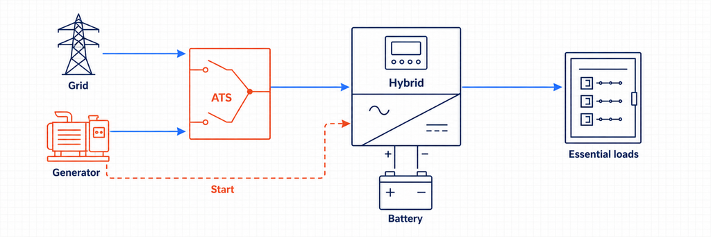
Для входного ATS между сетью и генератором рассчитайте ток генератора по его номиналу в кВА и сравните с максимальным допустимым током переменного тока на входе инвертора. Предположим, что однофазный генератор 15 кВА, 230 V питает инвертор-зарядное устройство. Его номинальный ток около 65,2 A. Если инвертор принимает только 50 A, его настройки или upstream-защита могут ограничивать ток зарядки и прохода, но цепь источника ATS всё равно должна быть согласована с автоматическим выключателем генератора, проводниками и фактическим путём нагрузки. Не следует считать программное ограничение входного тока заменой защиты цепи.
Работа генератора добавляет требования к управлению, которые схемы только с солнечными панелями не показывают: сигнал запуска, попытки запуска, задержка разогрева, проверка доступности источника, минимальное время работы, охлаждение, график работы, обратная связь о низком уровне топлива или неисправности и пороги состояния заряда батареи. Базовый ATS с определением напряжения может переключать нагрузки, но он может не согласовывать мощность зарядки или предотвращать перегрузку инверторного зарядного устройства на небольшом генераторе. Где гибридный инвертор управляет генератором, используйте указанные сухие контакты и последовательность управления. Если генератор запускается, но нагрузка не переключается, следуйте диагностической последовательности переключения генератора ATS чтобы найти первый отсутствующий контроллер или состояние пути питания.
Системы с тремя источниками могут требовать двух взаимозависимых этапов переключения или специально разработанного многорежимного распределительного устройства. IEC 60947-6-1:2026 отмечает границы вокруг многорежимного и гибридного TSE в своем описании области применения, поэтому полная сборка и конфигурация контроллера должны быть проверены, а не собраны из несвязанных переключателей и предполагаться как соответствующие.
Подключение к сети против автономного режима: что меняется в последовательности переключения?
Последовательность резервного питания гибридного подключения к сети
В нормальном режиме работы сеть устанавливает ссылку на сеть и может подавать нагрузки через проходной путь инвертора. Когда напряжение или частота сети выходят за пределы допустимого диапазона, одобренное изоляционное устройство размыкает соединение с сетью. Только после подтверждения изоляции инвертор, формирующий сеть, может подать питание на резервную шину. Когда сеть возвращается и остается стабильной в течение настроенной задержки, система повторно синхронизируется или выполняет открытый переход в соответствии с одобренной логикой управления.
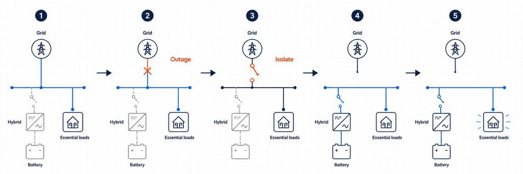
Генераторный автоматический переключатель (ATS), который просто обнаруживает “отсутствие напряжения”, может не знать, завершил ли инвертор изоляцию, стабилен ли его резервный шина или разрешено ли повторное подключение. Вот почему гибридные системы часто полагаются на интегрированный контроллер, специализированный резервный интерфейс или координацию с сухими контактами, указанную производителем инвертора.
Последовательность выбора источника в автономной системе
В автономной установке инвертор обычно является источником, формирующим сеть. Альтернативный ввод от сети или генератора становится приемлемым только после стабилизации его напряжения и частоты. ATS на входной стороне может выбирать между сетью и генератором перед подачей на инвертор/зарядное устройство. Внутреннее реле инвертора затем решает, пропустить ли принятый источник или продолжить поддерживать нагрузки от батарейного питания.
Если второй ATS на выходной стороне обеспечивает обход для обслуживания, его логика должна быть согласована с инвертором. Конструкция должна предотвращать подключение обходного источника к активному выходу инвертора, если оборудование не предназначено специально для синхронной параллельной работы. Механическая и электрическая блокировка не должна зависеть только от программных команд.
Полюса, переключение нейтрали и заземление
Не выбирайте 2P, 3P или 4P исключительно по простому правилу “одна фаза против трех фаз”. Определите, должен ли нейтраль оставаться надежно подключенным или быть переключаемым, как заземляется каждый источник, где существует связь нейтраль-земля и как работает защита от остаточного тока в каждом состоянии источника.
Система с однофазной линией и нейтралью может использовать двухполюсную схему переключения, где оба проводника должны быть переключены. Трехфазная четырехпроводная система может требовать четырехполюсного ATS, когда альтернативный источник создает отдельно выведенный или по-другому ссылающийся нейтраль. Другие системы намеренно сохраняют общий нейтраль. Правильная схема зависит от конструкции инвертора, местных норм, требований сети и утвержденной схемы производителя.
Неправильная обработка нейтрали может создать параллельные нейтральные пути, циркулирующий ток, неэффективную защиту от остаточного тока, ложные срабатывания или плавающую резервную систему. Создайте таблицу состояния нейтрали и земли для режима сети, режима острова, режима генератора и обхода для обслуживания. Если таблица не показывает одну целенаправленную стратегию соединения в каждом состоянии, проект не готов к установке.
Кратковременная нагрузка не равна постоянному току
Гибридные системы имеют два очень разных источника токов короткого замыкания. Сеть может обеспечить высокий потенциальный ток короткого замыкания. Инвертор обычно ограничивает выходной ток электронным образом и может подавать только скромное кратное значение номинального тока на короткое время. ATS все равно должен выдерживать и, где это необходимо, замыкать на худшую кратковременную нагрузку, доступную в его установленной точке.
Проверьте доступный ток короткого замыкания от каждого подключенного источника, устройства защиты на входе и условные данные по короткому замыканию или выдерживанию и отключению от производителя ATS. Не предполагайте, что ограниченный ток короткого замыкания инвертора делает малый автоматический переключатель приемлемым, если те же контакты подключены к мощному обходному устройству.
Для проектов, ориентированных на IEC, IEC 60947-6-1:2026 охватывает оборудование для переключения нагрузки между источниками. Для проектов в Северной Америке, обзор сертификации переключателей UL определяет категории UL 1008 для автоматических и неавтоматических переключателей. Всегда применяйте редакцию и правила установки, принятые уполномоченным органом проекта.
Время переключения: ATS не является автоматически ИБП
Переключение ATS включает в себя обнаружение, валидацию, механическую работу и время стабилизации. Даже быстрый переключатель может создать прерывание, достаточное для сброса контроллеров, контакторов, коммуникационного оборудования или компьютеров. Гибридный инвертор с внутренним реле переключения может поддерживать более короткий переход, чем отдельный электромеханический ATS, но фактическое значение должно быть указано в документации и тестировании системы.
Классифицируйте нагрузки по допустимости временного отключения. Освещение и холодильное оборудование могут терпеть кратковременное отключение. Серверы, ПЛК, медицинское оборудование и сетевые устройства могут требовать ИБП или пути безразрывного инвертора. Не обещайте “непрерывное питание” по номинальному току ATS.
Подробности управления и сенсоров, которые определяют, будет ли это работать
- Обнаружение источника: Измерьте напряжение и частоту непосредственно на клеммах источника. Производство PV или состояние заряда аккумулятора не эквивалентны здоровому резервному источнику переменного тока.
- Задержки переключения: Предотвращайте частые переключения при нестабильных условиях сети и давайте время стабилизации генератору или шине инвертора.
- Предпочтительный источник: Определите, является ли нормальным источником для каждого ATS резервный выход инвертора, обход сети или генератор.
- Сухие контакты: Подтвердите номиналы безнапряжных контактов, полярность логики и отказоустойчивость перед подключением управления инвертором или генератором.
- Логика возврата: Определите, возвращается ли система автоматически в сеть, ждёт восстановления аккумулятора или требует ручного подтверждения.
- Режим отказа: Решите, что происходит при отказе контроллера инвертора, мотора ATS, предохранителя датчика или канала связи.
Для проектов с необходимостью удалённого мониторинга выберите автоматический переключатель с требуемыми вспомогательными контактами или опциями связи. Обеспечьте независимость жёсткой блокировки источников от системы мониторинга.
Как читать технические паспорта инвертора и ATS вместе
Руководство по инвертору и технический паспорт ATS используют разные термины, поэтому создайте перекрёстную проверку вместо сравнения одной строки «номинального тока».
| Данные инвертора | Данные ATS для сравнения | Вопрос проектирования |
|---|---|---|
| Максимальный непрерывный резервный ток | Номинальный рабочий ток и категория использования | Могут ли контакты непрерывно пропускать выходной ток инвертора? |
| Максимальный ток входа переменного тока/прохода | Номинальный рабочий ток и ёмкость клемм | Может ли ATS пропускать больший ток сети или генератора? |
| Кривая перегрузки выхода | Режим включения/выключения и категория нагрузки | Вызовут ли события с двигателем или трансформатором стресс переключения или отключение инвертора? |
| Окна напряжения/частоты сети и резервного источника | Диапазон срабатывания контроллера и регулируемые пороги | Согласуются ли оба устройства с тем, что источник приемлем? |
| Внутреннее время переключения | Время работы ATS и преднамеренная задержка | Какое прерывание фактически испытает нагрузка? |
| Схема нейтрали/заземления | Схема коммутации 2P, 3P или 4P | Сохраняет ли каждое рабочее состояние утверждённую систему уравнивания потенциалов? |
| Максимальный вклад в ток повреждения | Выдерживаемый ток короткого замыкания/условный ток | Согласован ли переключатель для источников инвертора и электросети? |
| Сухой контакт или интерфейс связи | Входы, выходы и вспомогательные контакты контроллера | Могут ли устройства безопасно обмениваться разрешающими, аварийными и статусами положения? |
Если какое-либо значение отсутствует, запросите его перед выпуском спецификации переключателя. «Совместимость с солнечной энергией» не является электрическим параметром. Аналогично, «63 A ATS» не указывает, подходит ли устройство по напряжению, категории нагрузки, уровню короткого замыкания, последовательности переключения или сертификации на рынке.
Распространённые ошибки при подборе гибридных инверторных ATS
Подбор по мощности PV-массива, кВт
Массив мощностью 12 kWp не означает, что ATS пропускает 12 кВт. Ток в разных точках определяется номиналом переменного тока инвертора, пределом разряда аккумулятора, путём прохождения через сеть и требованиями к передаваемой нагрузке.
Использование только номинала выхода инвертора
Сеть или генератор могут пропускать через ATS ток, превышающий ток, который может выдать инвертор. Это главная причина фиксировать параметры прохождения и обхода отдельно.
Дублирование функции внутреннего переключения
Два автоматических контроллера могут выдавать противоречивые команды, создавать ненужные прерывания или обходить утверждённую последовательность изоляции инвертора. Используйте документированные отношения главного и подчинённого управления.
Предположение, что любой сетевой инвертор может обеспечить резервное питание
Министерство энергетики США объясняет, что сетевые инверторы отключаются при отсутствии сетевого питания, тогда как для автономной или резервной работы требуется возможность формирования сети. ATS сам по себе не обеспечивает такую возможность.
Игнорирование поведения нейтрали
Номинал тока может быть корректным, но система остаётся небезопасной из-за неправильного подключения нейтрали или заземления. Проверьте работу защитного проводника и УЗО в каждом состоянии переключения.
Рассмотрение ATS как устройства защиты от перегрузок
Переключатель меняет пути источников. Если выбранный продукт не является специально защитным устройством класса CB, всё равно требуются согласованные автоматические выключатели или предохранители.
Пусконаладочные испытания перед вводом системы в эксплуатацию
- Проверьте идентификацию проводников, момент затяжки клемм, последовательность фаз, полярность, непрерывность нейтрали и соединения защитного заземления.
- Подтвердите, что имена источников ATS соответствуют фактическим предпочтительным и резервным источникам.
- Измерьте напряжение и частоту сети, резервного инвертора и генератора в точках контроля.
- Смоделируйте отключение сети и подтвердите, что изоляция электросети происходит до подачи питания на островную шину.
- Подайте типичные критические нагрузки и убедитесь, что резервный ток остаётся в пределах лимита инвертора.
- Отключите или вызовите неисправность инвертора и проверьте ожидаемую реакцию обхода без обратной подачи на выход инвертора.
- Восстановите электросеть и подтвердите задержку повторного переключения, проверки стабильности источника и конечное рабочее состояние.
- Тестирование состояний низкого заряда аккумулятора, перегрузки, аварийной остановки, ручного управления и потери связи.
- Запись времени передачи, токов, сигналов тревоги, настроек контроллера и изменений фактической проводки.
Пусконаладочные работы должны выполняться квалифицированным персоналом с использованием утверждённой процедуры испытаний. Системы солнечной энергии и аккумуляторов, подключённые к электросети, могут подавать напряжение на проводники с нескольких сторон, даже если один разъединитель открыт.
Контрольный список технических требований ATS для гибридного солнечного проекта
| Пункт спецификации | Ввод проекта |
|---|---|
| Функция и расположение ATS | Выбор входного источника, обход резервного выхода или изоляция питания |
| Источник I / Источник II | Электросеть, генератор, резервный выход инвертора или утверждённая комбинация |
| Расчётный ток передаваемой нагрузки | По графику нагрузки и местным нормативам |
| Резервный ток инвертора | Максимальное непрерывное значение по данным производителя |
| Ток прохождения/обхода сети | Максимально допустимый на установленном месте |
| Номинальный рабочий ток | Выбирается после проверки нагрузки, снижения номинала и координации |
| Напряжение, частота, фазы | Соответствие обоих источников и нагрузки |
| Полюса и нейтраль | На основе утверждённой схемы заземления |
| Данные по токам короткого замыкания | Доступный ток короткого замыкания и согласованное защитное устройство |
| Метод переключения | Открытый переход, если не требуется утверждённый синхронизированный метод |
| Управление и обратная связь | Пороги срабатывания, задержки, сухие контакты, статус, связь |
| Доказательства совместимости | Утверждённая однолинейная схема инвертора и применимая сертификация |
Правило окончательного выбора
Правильный размер ATS для гибридного солнечного инвертора определяется по номиналу, требуемому на реальной электрической границе переключателя, а не по числу, указанному рядом с PV-массивом. Сначала подтвердите, что система имеет утверждённый метод формирования сети и изоляции. Затем сравните ток передаваемой нагрузки, резервный выходной ток инвертора и ток прохождения или обхода сети. Выберите наибольший достоверный ток через это место и завершите проект проверками по количеству полюсов, нейтрали, токам короткого замыкания, времени переключения питания, защите и контроллеру.
Для выбора, специфичного для проекта, отправьте JUTRION однолинейную схему, напряжение и количество фаз системы, модель инвертора, резервный выходной ток, номинал прохождения, график передаваемой нагрузки, доступный ток короткого замыкания и необходимые управляющие сигналы. Эти данные позволяют конфигурация ATS быть адаптирована к фактической гибридной или автономной архитектуре.
Часто задаваемые вопросы
Нужен ли мне ATS с гибридным солнечным инвертором?
Не всегда. Многие гибридные инверторы уже содержат внутреннее реле переключения или работают с выделенным интерфейсом резервного питания. Внешний ATS уместен только тогда, когда утверждённая производителем архитектура предусматривает функции, такие как выбор входа между сетью и генератором, обход выхода инвертора или резервирование для обслуживания. Добавление ещё одного ATS без проверки утверждённой схемы может привести к конфликтующей логике переключения.
Может ли ATS обеспечить работу сетевого солнечного инвертора во время отключения электроэнергии?
Нет. Обычный сетевой инвертор отключается при отсутствии сетевого питания. ATS не может придать ему способность формирования сети. Резервная работа требует совместимого оборудования для островного режима, инвертора, предназначенного для создания локальной шины переменного тока, и обычно аккумуляторного хранилища или другого стабильного источника энергии.
Должен ли размер ATS соответствовать номинальной мощности солнечного инвертора в кВт?
Не обязательно. ATS должен быть рассчитан на максимальный ток, который может проходить через его установленное место. Гибридный инвертор может выдавать 35 A в резервном режиме, при этом пропуская через сеть ток до 63 A. Если ATS обслуживает этот сетевой путь, то за начальный класс тока принимается больший достоверный ток — не мощность PV-массива или только кВт инвертора.
Как перевести кВА гибридного инвертора в ток ATS?
Для однофазных систем разделите кажущуюся мощность в ВА на напряжение: I = S ÷ V. Для сбалансированных трёхфазных систем используйте I = S ÷ (√3 × V). Сравните результат с заявленным максимальным током переменного тока инвертора, так как паспортный предел имеет приоритет над идеальным расчётом. Затем проверьте, какой ток выше — проходящий через сеть или требуемая нагрузка при переключении.
Где должен устанавливаться ATS — до или после гибридного инвертора?
Это зависит от его предназначения. ATS на стороне входа может выбирать между сетью и генератором до инвертора/зарядного устройства. ATS на стороне выхода может выбирать резервный выход инвертора или прямой обход сети для панели с критической нагрузкой. Устройство переключения на границе обслуживания может быть частью выделенного интерфейса резервного питания. Эти позиции имеют разные требования к току, нейтрали, датчикам и управлению.
Нужен ли для солнечного инвертора ATS на 2 полюса или 4 полюса?
Выбирайте количество полюсов исходя из числа фаз и утверждённой схемы нейтрали и заземления. В некоторых системах нейтраль остаётся неизменной; в других её необходимо переключать, чтобы избежать параллельных путей или обеспечить отдельный источник. Не применяйте универсальное правило «одна фаза = 2P» или «три фазы = 4P» без проверки руководства инвертора, местных норм, защиты от остаточного тока и схемы заземления.
Можно ли использовать ATS с номиналом больше, чем выходной ток инвертора?
Да, при условии, что напряжение, количество полюсов, режим эксплуатации, класс отключающей способности, защита, управление и сертификация соответствуют требованиям. Более крупный ATS обычно требуется, когда ток обхода сети превышает резервный ток инвертора. Однако больший переключатель не увеличивает выход инвертора или ёмкость аккумулятора; резервные нагрузки должны оставаться в пределах возможностей инвертора.
Достаточно ли быстр ATS, чтобы заменить ИБП?
Не обязательно. Обнаружение источника, проверка, механическая операция и стабилизация инвертора могут вызвать прерывание питания. Чувствительные компьютеры, серверы, системы управления, коммуникационное оборудование или медицинские нагрузки могут по-прежнему требовать ИБП или проверенный бесперебойный путь питания. Оценивайте полное время переключения системы, а не только номинал тока ATS.
Ссылки
