

สวิตช์โอนอัตโนมัติไม่สลับไปยังเครื่องกำเนิดไฟฟ้า? สาเหตุและลำดับการวินิจฉัย
คำตอบด่วน: ทำไม ATS จึงไม่สลับไปยังเครื่องกำเนิดไฟฟ้า?
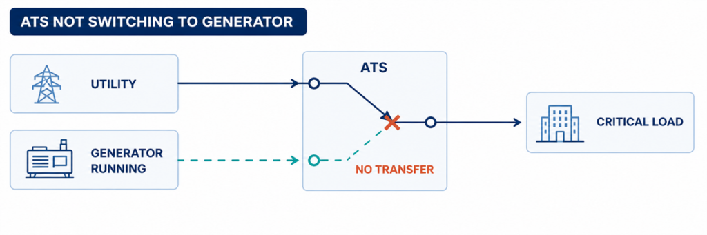
สวิตช์โอนอัตโนมัติไม่สลับไปยังเครื่องกำเนิดไฟฟ้าในขณะที่เครื่องกำเนิดกำลังทำงานหากสวิตช์โอนอัตโนมัติไม่สลับไปยังพลังงานเครื่องกำเนิด ให้ตรวจสอบขั้นตอนแรกที่ล้มเหลวในลำดับการโอน ยืนยันว่า ATS ตรวจพบแหล่งจ่ายไฟฟ้าสาธารณะที่ไม่ยอมรับได้หรือไม่, ออกคำสั่งสตาร์ทเครื่องยนต์หรือไม่, รับแรงดันและความถี่เครื่องกำเนิดที่ยอมรับได้หรือไม่, ผ่านเวลาหน่วงที่ตั้งโปรแกรมไว้หรือไม่, ทำงานกลไกสวิตช์หรือไม่ และส่งกลับข้อมูลตำแหน่งที่ถูกต้องหรือไม่ สถานะที่ขาดหายไปแรกมักระบุจุดบกพร่องได้
เครื่องกำเนิดที่กำลังทำงานไม่ได้หมายความว่า ATS พร้อมโอนแล้ว เบรกเกอร์เอาต์พุตเครื่องกำเนิดอาจเปิดอยู่, แรงดันหรือความถี่อาจอยู่นอกช่วงที่ตัวควบคุมยอมรับ, เฟสอาจขาด, อินพุตอนุญาตอาจไม่มา หรือกลไกอาจล้มเหลวหลังจากตัวควบคุมออกคำสั่ง การแก้ไขปัญหาจะรวดเร็วขึ้นเมื่อเช็คเงื่อนไขเหล่านี้ตามลำดับ แทนการเปลี่ยนตัวควบคุมก่อน
ขอบเขตความปลอดภัย: ตู้ ATS อาจมีสายไฟฟ้าสาธารณะและเครื่องกำเนิดไฟฟ้าที่มีไฟฟ้าแรงสูงพร้อมกัน ผู้ปฏิบัติงานสามารถบันทึกตัวชี้วัด, สัญญาณเตือน และเหตุการณ์ตัวควบคุมโดยไม่ต้องเปิดช่องที่มีไฟฟ้า การวัดแรงดัน, ทดสอบความต่อเนื่อง, การทำงานกลไกด้วยมือ และการตรวจสอบภายในต้องปฏิบัติตามคู่มืออุปกรณ์, ขั้นตอนการสวิตช์ไซต์ และกฎความปลอดภัยทางไฟฟ้าที่เกี่ยวข้อง และควรดำเนินการโดยผู้มีคุณสมบัติเฉพาะเท่านั้น
อ่านความล้มเหลวเป็นลำดับการโอนที่ขัดข้อง
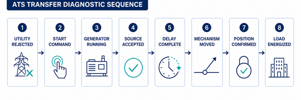
ลำดับการวินิจฉัย ATS ตั้งแต่ไฟฟ้าสาธารณะล้มเหลวจนถึงการโอนโหลดเครื่องกำเนิดการโอนอัตโนมัติเป็นชุดของการตัดสินใจมากกว่าการเคลื่อนไหวเพียงครั้งเดียว ลำดับทั่วไปจากยูทิลิตี้ไปยังเครื่องกำเนิดไฟฟ้าคือ:
- ตัวควบคุมตรวจสอบแหล่งจ่ายไฟปกติ
- แหล่งจ่ายไฟปกติไม่เป็นที่ยอมรับเกินกว่าช่วงเวลาหน่วงการตรวจจับที่ตั้งโปรแกรมไว้
- ATS เปลี่ยนการติดต่อสตาร์ทเครื่องยนต์เพื่อสั่งการเครื่องกำเนิดไฟฟ้า
- เครื่องกำเนิดไฟฟ้าสตาร์ทและสร้างแรงดันไฟฟ้าและความถี่ที่ขั้วแหล่งจ่ายไฟสำรองของ ATS
- ตัวควบคุมยอมรับแหล่งจ่ายไฟสำรองหลังจากช่วงเวลาหน่วงการเสถียรภาพ
- อินเตอร์ล็อกและการอนุญาตให้คำสั่งโอน
- กลไกตัดการเชื่อมต่อแหล่งจ่ายไฟปกติและเชื่อมต่อแหล่งจ่ายไฟสำรองตามการออกแบบการเปลี่ยนผ่าน
- ขั้วต่อเสริมยืนยันตำแหน่งใหม่
- แรงดันไฟฟ้าแสดงที่ขั้วโหลดและเครื่องกำเนิดไฟฟ้ารับภาระที่ถูกโอน
เริ่มต้นด้วยบันทึกเหตุการณ์ของตัวควบคุมและตัวบ่งชี้แหล่ง/ตำแหน่งบนแผงหน้า จดบันทึกขั้นตอนสุดท้ายที่ยืนยัน หากเครื่องกำเนิดไฟฟ้าไม่เคยได้รับคำสั่งสตาร์ท การตรวจสอบขั้วไฟฟ้าจะไม่ช่วยแก้ปัญหา หากตัวควบคุมแสดงว่าเครื่องกำเนิดไฟฟ้าพร้อมใช้งานแต่กลไกไม่เคลื่อนที่ การเปลี่ยนการตั้งค่าเครื่องกำเนิดไฟฟ้าก็ไม่ช่วยเช่นกัน
บันทึกพารามิเตอร์เหล่านี้ก่อนเปลี่ยนการตั้งค่า
พารามิเตอร์ที่มีประโยชน์คือค่าที่กำหนดว่าตัวควบคุมจะยอมรับแหล่งจ่ายไฟและอนุญาตการเคลื่อนที่หรือไม่ จดบันทึกการตั้งค่าปัจจุบันและค่าที่สังเกตได้ก่อนทำการเปลี่ยนแปลง หน้าต่างการยอมรับและช่วงเวลาหน่วงเป็นไปตามตัวควบคุมและโครงการ ตารางนี้ระบุสิ่งที่ต้องบันทึก ไม่ใช่ค่าที่ตั้งไว้ทั่วไป
| พารามิเตอร์ | สิ่งที่ต้องบันทึก | เหตุผลที่สำคัญ | แหล่งข้อมูลหลักฐาน |
|---|---|---|---|
| แรงดันไฟฟ้าปกติของแหล่งจ่าย | ค่าปกติที่ตั้งไว้และการจัดเรียงเฟสของระบบ | การตั้งค่าผิดพลาดอาจทำให้แหล่งจ่ายไฟที่ปกติดูเหมือนไม่เป็นที่ยอมรับ | ไฟล์การตั้งค่าที่ได้รับอนุมัติ ป้ายชื่อ และแผนผังเส้นเดียว |
| ค่าขีดจำกัดแรงดันต่ำและแรงดันเกิน | ค่าการทำงาน/การคืนค่าหรือเปอร์เซ็นต์การตั้งค่าสำหรับแต่ละแหล่งจ่ายไฟ | ATS จะโอนหลังจากแรงดันไฟฟ้าแหล่งจ่ายไฟข้ามขีดจำกัดและเวลาหน่วงที่ใช้บังคับ | เมนูตัวควบคุมและลำดับการทำงาน |
| ขีดจำกัดความถี่ | ค่าการยอมรับความถี่ต่ำ/สูง | เครื่องกำเนิดไฟฟ้าที่กำลังทำงานอาจยังถูกปฏิเสธในขณะที่ความเร็วไม่เสถียร | เมนูตัวควบคุมและข้อมูลเครื่องกำเนิดไฟฟ้า |
| การตรวจสอบเฟส | ฟังก์ชันการสูญเสียเฟส ลำดับเฟส และความไม่สมดุลของเฟสเปิดใช้งาน | เงื่อนไขเฟสผิดพลาดเพียงหนึ่งอย่างสามารถบล็อกการยอมรับแหล่งจ่ายไฟ | สถานะและการตั้งค่าตัวควบคุม |
| เวลาหน่วงการล้มเหลวของแหล่งจ่ายไฟ | เวลาจากยูทิลิตี้ที่ไม่เป็นที่ยอมรับถึงการสั่งสตาร์ทเครื่องยนต์ | ป้องกันการสตาร์ทในกรณีที่เกิดความผิดปกติชั่วคราว | แสดงตัวจับเวลาทำงานและการตั้งค่าที่ได้รับการอนุมัติ |
| ดีเลย์การเสถียรของเครื่องกำเนิดไฟฟ้า | เวลาหลังจากแหล่งจ่ายไฟสำรองเป็นที่ยอมรับก่อนการโอนถ่าย | อนุญาตให้แรงดันไฟฟ้าและความถี่นิ่งตัว | ตัวจับเวลาควบคุมและบันทึกเหตุการณ์ |
| หมดเวลาการโอนถ่ายและกลไก | เวลาที่อนุญาตสำหรับคำสั่งเปิด/ปิดและการยืนยันตำแหน่ง | หมดเวลาที่แยกความแตกต่างระหว่างการเคลื่อนไหวช้า/ล้มเหลวกับดีเลย์ปกติ | รหัสสัญญาณเตือน, บันทึกเหตุการณ์ และคู่มือคอนโทรลเลอร์ |
| ดีเลย์การโอนกลับและการระบายความร้อน | เวลายืนยันการกลับสู่ระบบไฟฟ้าสาธารณะและเวลาการทำงานของเครื่องกำเนิดไฟฟ้าแบบไม่มีโหลด | อธิบายเหตุผลที่ ATS ยังคงอยู่บนเครื่องกำเนิดไฟฟ้าหรือทำไมเครื่องยนต์ยังคงทำงาน | การตั้งค่าคอนโทรลเลอร์และเครื่องกำเนิดไฟฟ้า |
| ตรรกะการติดต่อสตาร์ทเครื่องยนต์ | ปิดเพื่อสตาร์ทหรือเปิดเพื่อสตาร์ท; หมายเลขเทอร์มินัลและสถานะที่สังเกตได้ | ตรรกะที่ไม่เข้ากันป้องกันไม่ให้เครื่องกำเนิดไฟฟ้าได้รับคำสั่งที่ตั้งใจไว้ | แผนภาพวงจร ATS และแผนภาพการสตาร์ทเครื่องกำเนิดไฟฟ้าระยะไกล |
| แหล่งจ่ายไฟควบคุม | แรงดันไฟฟ้าควบคุม AC/DC ที่กำหนดและค่าระหว่างเหตุการณ์ล้มเหลว | แรงดันไฟฟ้าควบคุมตกต่ำอาจรีเซ็ตคอนโทรลเลอร์หรือทำให้แอคชูเอเตอร์หยุดทำงาน | แผนภาพวงจรที่สั่งและการวัดที่ผ่านการรับรอง |
| อินพุตอนุญาตและอินพุตห้าม | สถานะปกติและสถานะในระหว่างการโอนถ่ายล้มเหลว | สวิตช์ภายนอกอาจตั้งใจบล็อกการเคลื่อนไหว | หน้าจอสถานะ I/O, บันทึก PLC/BMS และแผนภาพการเดินสาย |
| ฟีดแบ็กตำแหน่ง | สถานะขั้วติดต่อแบบปกติเปิด, ปิดสลับ และตำแหน่งกลาง | คอนโทรลเลอร์อาจสั่งงานถูกต้องแต่ไม่สามารถยืนยันการเคลื่อนไหวได้ | หน้าจอ I/O ของคอนโทรลเลอร์และแผนภาพสวิตช์เสริม |
| สถานะที่สังเกตได้ | พื้นที่ที่มีความผิดพลาดเป็นไปได้ | หลักฐานถัดไปที่ดีที่สุด |
|---|---|---|
| ระบบไฟฟ้าสาธารณะล้มเหลว; เครื่องกำเนิดไฟฟ้าไม่สตาร์ท | โหมด ATS, การตรวจจับ, ดีเลย์สตาร์ท, การติดต่อสตาร์ท หรือการเดินสายควบคุม | สถานะแหล่งจ่ายปกติ, ตัวจับเวลาทำงาน, สัญญาณเริ่มต้นเอาต์พุต และสถานะโหมดรีโมตของเครื่องกำเนิดไฟฟ้า |
| เครื่องกำเนิดไฟฟ้าทำงาน; ATS แจ้งว่าแหล่งจ่ายไม่พร้อมใช้งาน | เอาต์พุตเครื่องกำเนิดไฟฟ้า, เบรกเกอร์, แรงดัน/ความถี่, เฟส หรือวงจรตรวจจับ | สัญญาณแสดงว่าเครื่องกำเนิดไฟฟ้าพร้อมใช้งาน, ค่าที่อ่านได้จากคอนโทรลเลอร์ และการวัดที่ถูกต้องที่ขั้วแหล่งจ่าย |
| เครื่องกำเนิดไฟฟ้าพร้อมใช้งาน; ไม่มีคำสั่งโอนโหลด | ดีเลย์, ห้าม, อนุญาต, โหมดทดสอบ หรือตรรกะควบคุม | ตัวจับเวลาทำงาน, อินพุตห้าม, สัญญาณเตือน และบันทึกเหตุการณ์ |
| ปรากฏคำสั่งโอนโหลด; กลไกไม่เคลื่อนที่ | แหล่งจ่ายควบคุม, ตัวกระตุ้น, ขดลวด, มอเตอร์, การล็อกกัน หรืออุปสรรคทางกล | เอาต์พุตคำสั่ง, แหล่งจ่ายตัวกระตุ้น และสัญญาณตอบกลับตำแหน่ง |
| กลไกเคลื่อนที่; โหลดยังคงไม่มีไฟฟ้า | เปิดเบรกเกอร์เครื่องกำเนิดไฟฟ้า, เส้นทางสัมผัสเสียหาย, การเชื่อมต่อเอาต์พุต หรือการป้องกันด้านล่าง | ตำแหน่ง ATS, แรงดันแหล่งจ่ายและโหลด, สถานะเบรกเกอร์ |
| เกิดการโอนโหลด; เครื่องกำเนิดไฟฟ้าทริปหรือแรงดันไฟฟ้าลดลง | ขั้นตอนโหลด, ความจุเครื่องกำเนิดไฟฟ้า, กระแสเริ่มต้น, การตั้งค่าการป้องกัน หรือปัญหาเฟส | บันทึกเหตุการณ์เครื่องกำเนิดไฟฟ้า, กระแส, ความถี่ และแรงดันไฟฟ้าระหว่างการโอนโหลด |
ยืนยันการรับรู้แหล่งจ่ายจากการล้มเหลวของยูทิลิตี้ถึงความพร้อมใช้งานของเครื่องกำเนิดไฟฟ้า
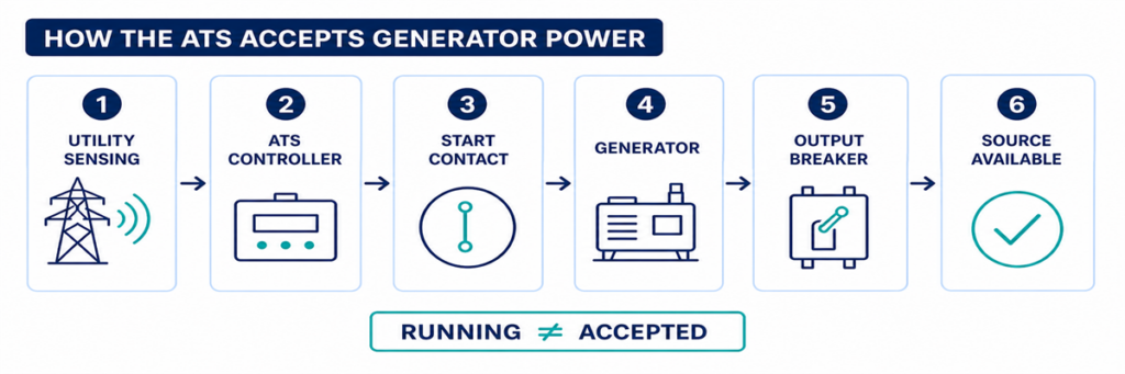
วิธีที่ ATS ตรวจจับและยอมรับพลังงานเครื่องกำเนิดไฟฟ้าก่อนการโอนโหลดจุดตรวจสอบ 1: ATS ปฏิเสธแหล่งจ่ายยูทิลิตี้จริงหรือไม่?
ATS โดยปกติจะยังคงอยู่ที่ยูทิลิตี้ในขณะที่คอนโทรลเลอร์พิจารณาว่าแหล่งจ่ายนั้นยอมรับได้ ผู้ปฏิบัติงานสถานที่อาจเห็นไฟสลัว, การดับบางส่วน หรือแผงวงจรด้านล่างล้มเหลว ในขณะที่จุดตรวจจับแรงดันที่ ATS ยังคงอยู่ในขอบเขตที่ตั้งโปรแกรมไว้ ในกรณีนั้น การปฏิเสธการโอนโหลดอาจเป็นพฤติกรรมที่ถูกต้อง ไม่ใช่ความผิดพลาดของ ATS
ตรวจสอบสัญญาณแสดงแหล่งจ่ายปกติและค่าคอนโทรลเลอร์สำหรับแต่ละเฟสที่ตรวจสอบ เปรียบเทียบกับฟังก์ชันการตั้งค่าต่ำกว่าแรงดัน, เกินแรงดัน, ความถี่, การสูญเสียเฟส และลำดับเฟสที่ตั้งไว้สำหรับคอนโทรลเลอร์ที่สั่งซื้อ นอกจากนี้ตรวจสอบเวลาหน่วงเมื่อแหล่งจ่ายปกติล้มเหลว การรบกวนสั้นอาจหายไปก่อนเวลานี้หมดลง เพื่อป้องกันการสตาร์ทเครื่องกำเนิดไฟฟ้าที่ไม่จำเป็น.
สาเหตุทั่วไปที่คอนโทรลเลอร์ยังคงยอมรับยูทิลิตี้
- การดับไฟเกิดขึ้นด้านล่างจุดตรวจจับของ ATS
- มีเพียงวงจรหรือสายจ่ายโหลดล้มเหลว
- การตั้งค่าการรับ/ตัดแรงดันต่ำไม่ตรงกับช่วงการทำงานที่ตั้งใจไว้
- ฟิวส์ตรวจจับหรือสายไฟผิดพลาดทำให้คอนโทรลเลอร์ได้รับสถานะผิดพลาด
- คอนโทรลเลอร์อ่านแรงดันไฟฟ้าปกติหรือการกำหนดค่าแหล่งจ่ายผิดพลาด
- เวลาหน่วงการล้มเหลวของแหล่งจ่ายยังไม่หมด
อย่าปรับลดเกณฑ์แรงดันไฟฟ้าเพียงเพื่อบังคับให้โอนโหลด ก่อนอื่นให้กำหนดขอบเขตคุณภาพแหล่งจ่ายที่ตั้งใจไว้และตรวจสอบให้แน่ใจว่าการตั้งค่าการตรวจจับตรงกับระบบ นิวทรัลหลวมหรือเฟสขาดอาจสร้างแรงดันไฟฟ้าอันตรายที่ต้องตรวจสอบ ไม่ใช่การขยายขอบเขตการยอมรับ
จุดตรวจสอบ 2: มีการสั่งสตาร์ทเครื่องกำเนิดไฟฟ้าหรือไม่?
เมื่อแหล่งจ่ายปกติถูกปฏิเสธ คอนโทรลเลอร์ ATS หลายรุ่นสำหรับยูทิลิตี้ไปเครื่องกำเนิดไฟฟ้าจะทำงานรีเลย์แห้งที่เชื่อมต่อกับวงจรสตาร์ทรีโมตของเครื่องกำเนิดไฟฟ้า รีเลย์อาจปิดเพื่อสตาร์ทหรือเปิดเพื่อสตาร์ท ขึ้นอยู่กับการออกแบบของเครื่องกำเนิดไฟฟ้าและ ATS อุปกรณ์ทั้งสองต้องใช้ตรรกะที่เข้ากันได้
ยืนยันก่อนว่า ATS อยู่ใน AUTO หรือโหมดการทำงานปกติ โหมดบำรุงรักษา, ตรวจสอบ, แมนนวล, ห้าม, ควบคุมไฟไหม้ และโหมดทดสอบ สามารถบล็อกการโอนอัตโนมัติหรือเปลี่ยนลำดับการสตาร์ทได้โดยเจตนา บันทึกสัญญาณเตือนและสถานะอินพุตก่อนรีเซ็ตใดๆ เพราะการรีเซ็ตอาจลบหลักฐานที่มีประโยชน์ที่สุด
หากคอนโทรลเลอร์แสดงว่าสัญญาณเริ่มต้นทำงานแล้วแต่เครื่องกำเนิดไฟฟ้ายังหยุดอยู่ ให้ตรวจสอบอินเทอร์เฟซระหว่าง ATS กับเครื่องกำเนิดไฟฟ้า สาเหตุทั่วไปได้แก่ สายควบคุมขาด, การใช้ขั้วเปิดปกติหรือปิดปกติผิด, ขั้วต่อหลวม, ฟิวส์ควบคุมขาด, โหมดรีโมตเครื่องกำเนิดไฟฟ้าถูกปิดใช้งาน, แบตเตอรี่สตาร์ทต่ำ หรือสัญญาณเตือนปิดเครื่องกำเนิดไฟฟ้า
ไม่ควรใช้สายจัมเปอร์ข้ามขั้วเริ่มต้นโดยพลการ เว้นแต่ขั้นตอนของผู้ผลิตจะระบุไว้อย่างชัดเจนและการทดสอบควบคุมโดยบุคลากรที่มีคุณสมบัติ การสตาร์ทเครื่องกำเนิดไฟฟ้าโดยไม่คาดคิดอาจทำให้ผู้ที่ทำงานกับเครื่องยนต์ ไดนาโม หรือวงจรด้านล่างได้รับอันตรายได้
จุดตรวจสอบที่ 3: กำลังไฟฟ้าจากเครื่องกำเนิดถึง ATS หรือไม่?
เครื่องกำเนิดไฟฟ้าอาจทำงานอยู่โดยไม่จ่ายกำลังไฟฟ้าที่ใช้งานได้ไปยังสวิตช์โอนแหล่งจ่าย สถานะของเครื่องยนต์และสถานะไฟฟ้าของแหล่งจ่ายสำรองเป็นจุดตรวจสอบแยกกัน
ตรวจสอบสัญญาณแสดงสถานะเครื่องกำเนิดพร้อมใช้งานจากตัวควบคุม ตรวจสอบว่าเบรกเกอร์เอาต์พุตของเครื่องกำเนิดปิดอยู่หรือไม่ และตรวจสอบว่าอุปกรณ์แยกวงจร เบรกเกอร์ฟีดเดอร์ หรือฟิวส์ภายนอกระหว่างเครื่องกำเนิดกับ ATS เปิดอยู่หรือไม่ ตรวจสอบตัวควบคุมเครื่องกำเนิดสำหรับสัญญาณเตือนแรงดันเกิน แรงดันต่ำ ความเร็วเกิน ความเร็วต่ำ การกระตุ้น เฟส หรือการตัดเบรกเกอร์
เมื่อได้รับอนุญาตให้ทดสอบแบบมีไฟฟ้า บุคลากรที่มีคุณสมบัติควรวัดแหล่งจ่ายที่ขั้ว ATS ไม่ใช่เพียงแค่ที่จอแสดงผลของเครื่องกำเนิดเท่านั้น ยืนยันแรงดันเฟสต่อเฟสและถ้ามี แรงดันเฟสต่อกลาง ความถี่ และการหมุนเฟสที่ถูกต้อง การอ่านค่าที่ดีที่ไดนาโมแต่ไม่มีค่าที่ ATS ชี้ไปยังเบรกเกอร์ สายไฟ การต่อสาย หรืออุปกรณ์ป้องกันระหว่างกลาง
เหตุผลที่ ATS อาจปฏิเสธเครื่องกำเนิดที่กำลังทำงาน
- แรงดันไฟฟ้าอยู่นอกช่วงยอมรับที่ตั้งโปรแกรมไว้
- ความถี่ยังไม่เสถียร
- ขาดเฟสหนึ่งเฟสหรือเรียงลำดับเฟสไม่ถูกต้อง
- แรงดันไฟฟ้าปกติหรือตัวคูณการวัดของตัวควบคุมตั้งค่าไม่ถูกต้อง
- เบรกเกอร์ของเครื่องกำเนิดเปิดอยู่หรือเกิดการตัด
- ฟิวส์ ตัวแปลง หรือสายไฟเซ็นเซอร์ขาด
- เครื่องกำเนิดถึงสภาวะที่ยอมรับได้เพียงชั่วคราวแล้วหลุดออกอีกครั้ง
อย่าถือว่าแรงดันไฟฟ้าบนแผงไม่มีโหลดของเครื่องกำเนิดเป็นหลักฐานสุดท้าย ค่าที่เกี่ยวข้องคือสภาวะแหล่งจ่ายที่ ATS รับรู้ และแรงดันไฟฟ้าและความถี่ที่รักษาไว้เมื่อมีการโหลด
ติดตามคำสั่งโอน กลไก และสัญญาณตอบกลับตำแหน่ง
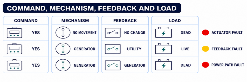
การเปรียบเทียบการวินิจฉัยคำสั่ง ATS กลไกสวิตชิ่ง สัญญาณตอบกลับตำแหน่ง และแรงดันโหลดจุดตรวจสอบที่ 4: มีตัวจับเวลาหรือสัญญาณอนุญาตยับยั้งการโอนหรือไม่?
เมื่อแหล่งจ่ายสำรองอยู่ในสภาพที่ยอมรับได้ การโอนอาจถูกเลื่อนออกไปโดยเจตนา ตัวจับเวลาการอุ่นเครื่องเครื่องกำเนิดช่วยให้แรงดันและความถี่เสถียร แอปพลิเคชันอื่นๆ อาจต้องการการยืนยันการลดโหลด ลำดับลิฟต์หรือมอเตอร์ สถานะ UPS สัญญาณไฟไหม้ การอนุญาตกระบวนการ หรือการอนุญาตระยะไกลก่อนที่สวิตช์จะเคลื่อนที่
ใช้จอแสดงผลของตัวควบคุมเพื่อระบุว่าตัวจับเวลาใดทำงานอยู่และกำลังนับเวลาหรือไม่ เปรียบเทียบการตั้งค่ากับลำดับการทำงานที่ได้รับอนุมัติแทนที่จะสมมติว่าการหน่วงเวลานั้นมากเกินไป ในตัวควบคุมบางรุ่น ปุ่มทดสอบหรือฟังก์ชันข้ามหน่วงเวลาสามารถย่อระยะเวลาการทดสอบได้; ต้องใช้เฉพาะตามขั้นตอนเฉพาะรุ่นและเมื่อโหลดพร้อมโอนเท่านั้น
หากตัวจับเวลาสิ้นสุดแต่ไม่มีคำสั่งตามมา ให้ตรวจสอบอินพุตลอจิกสำหรับการยับยั้งการโอน การยับยั้งฉุกเฉิน การตัดภายนอก ความชอบแหล่งจ่าย การโอนกลับด้วยมือ หรือการยืนยันการลดโหลด คอนแทคฟิลด์ที่จ่ายไฟตลอดเวลาอาจทำให้ ATS ดูเหมือนมีปัญหาในขณะที่กำลังปฏิบัติตามล็อกอินเตอร์ล็อกที่ตั้งโปรแกรมไว้
จุดตรวจสอบที่ 5: ตัวควบคุมสั่งกลไกหรือไม่?
จุดตรวจสอบนี้แยกปัญหาลอจิกออกจากปัญหาตัวกระตุ้นหรือสวิตช์พลังงาน ตรวจสอบบันทึกเหตุการณ์สำหรับคำสั่งเช่น เปิดปกติ ปิดสำรอง เริ่มโอน หรือไม่สามารถปิดได้ เปรียบเทียบคำสั่งที่แสดงกับตัวบ่งชี้ตำแหน่งจริง
หากไม่มีคำสั่งเกิดขึ้นแม้ว่าแหล่งจ่ายและเงื่อนไขอนุญาตดูถูกต้อง สาเหตุที่เป็นไปได้รวมถึงการยับยั้งที่เปิดใช้งาน ข้อผิดพลาดการตั้งค่า เอาต์พุตล้มเหลว ปัญหาไฟเลี้ยงตัวควบคุม หรือความผิดภายในตัวควบคุม ตรวจสอบแหล่งจ่ายและขั้วต่อของตัวควบคุมตามคำแนะนำการบริการของผู้ผลิตก่อนตัดสินว่าตัวควบคุมเสีย
หากมีคำสั่งเกิดขึ้น ให้ตรวจสอบว่าแรงดันควบคุมถึงมอเตอร์ โซลินอยด์ ชุดตัดชัน หรือขดลวดปิดหรืออุปกรณ์เสริมเบรกเกอร์ที่เกี่ยวข้องหรือไม่ วงจรที่แน่นอนขึ้นอยู่กับว่า ATS ใช้กลไกสวิตชิ่งเฉพาะ ตัวตัดวงจรแบบคอนแทคเตอร์ หรือเบรกเกอร์มอเตอร์ อย่าใช้แผนผังขั้วทั่วไปกับกลไกที่แตกต่างกัน
จุดตรวจสอบที่ 6: กลไกสวิตชิ่งสามารถเคลื่อนที่จนเสร็จสมบูรณ์หรือไม่?
ตัวควบคุมอาจออกคำสั่งที่ถูกต้องในขณะที่กลไกพลังงานยังคงอยู่ในตำแหน่งก่อนหน้า หรือหยุดระหว่างตำแหน่ง สาเหตุที่เป็นไปได้ ได้แก่:
- แรงดันควบคุมตัวกระตุ้นขาดหรือแรงดันต่ำ;
- ฟิวส์ควบคุมขาดหรือขดลวดหม้อแปลงควบคุมด้านทุติยภูมิเปิด;
- มอเตอร์ โซลินอยด์ ขดลวดปิด หรือวงจรตัดชันล้มเหลว;
- กลไกสปริงชาร์จหรือกลไกเก็บพลังงานที่ยังไม่พร้อมใช้งาน;
- ล็อกอินเตอร์ล็อกทางไฟฟ้าหรือกลไกที่ยังไม่ปล่อย;
- เบรกเกอร์ที่ตัดและต้องรีเซ็ตก่อนปิด;
- การติดขัด การปนเปื้อน การกัดกร่อน หรือสิ่งกีดขวางจากการขนส่ง/บำรุงรักษา;
- สวิตช์จำกัดและคอนแทคเสริมที่ผิดตำแหน่งหรือเสียหาย
ฟังเสียงคำสั่งและสังเกตสัญญาณตำแหน่งภายนอกที่ได้รับอนุมัติ แต่ไม่ควรสั่งกลไกที่ติดขัดหรือสั่นซ้ำๆ การสั่งซ้ำๆ อาจทำให้ขดลวดหรือมอเตอร์ร้อนเกินไปและทำลายคอนแทคหรือกลไกเชื่อมต่อ
การปฏิบัติการด้วยมือไม่ใช่ทางลัดแก้ไขปัญหาไฟฟ้าสดทั่วไป คำแนะนำของผู้ผลิตมักกำหนดให้แหล่งจ่ายไฟทั้งจากยูทิลิตี้และเครื่องกำเนิดไฟฟ้าต้องถูกแยกออกก่อนใช้มือจับแบบแมนนวล ปฏิบัติตามขั้นตอนที่ถูกต้องสำหรับรุ่นนั้น ๆ ตรวจสอบให้แน่ใจว่าไม่มีแรงดันไฟฟ้า และรักษาความปลอดภัยจากพลังงานที่เก็บไว้
จุดตรวจสอบที่ 7: ข้อมูลตำแหน่งย้อนกลับตรงกับเส้นทางพลังงานหรือไม่?
ตัวควบคุมอาจใช้คอนแทคเสริมเพื่อยืนยันว่าแหล่งจ่ายไฟหนึ่งเปิดและอีกแหล่งปิด หากกลไกเคลื่อนที่แต่คอนแทคย้อนกลับไม่เปลี่ยนแปลง ตัวควบคุมสามารถรายงานการโอนล้มเหลวหรือบล็อกคำสั่งถัดไป ปลั๊กหลวม การเดินสายคอนแทคเสริมผิดพลาด ไมโครสวิตช์เสีย หรือการจัดตำแหน่งเชิงกลผิดสามารถสร้างความไม่ตรงกันนี้ได้
เปรียบเทียบหลักฐานอิสระสามชิ้น:
- สถานะที่ตัวควบคุมสั่งการ;
- ตัวบ่งชี้ตำแหน่งเชิงกลที่ได้รับอนุมัติ;
- สถานะไฟฟ้าที่ขั้วโหลด.
สถานะเหล่านี้ควรตรงกัน หากตัวควบคุมระบุว่า “โหลดอยู่บนเครื่องกำเนิด” แต่ขั้วโหลดยังไม่มีแรงดัน ให้ตรวจสอบเบรกเกอร์เครื่องกำเนิด คอนแทคจ่ายไฟ การเชื่อมต่อบัส และอุปกรณ์ป้องกันด้านล่าง หากมีแรงดันไฟฟ้าที่โหลดแต่ตัวควบคุมไม่ยืนยันตำแหน่ง วงจรย้อนกลับเป็นผู้ต้องสงสัยที่สำคัญกว่า
เมื่อ ATS โอนโหลดแต่เครื่องกำเนิดไม่สามารถรับโหลดได้
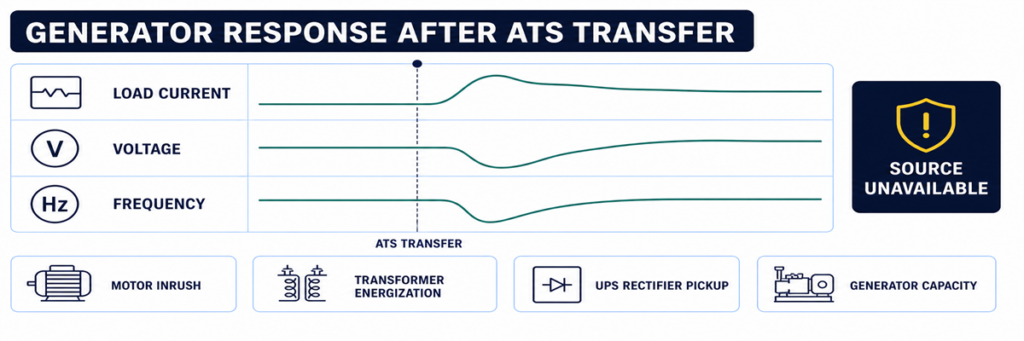
แรงดันและความถี่ของเครื่องกำเนิดลดลงหลังจากสวิตช์โอนอัตโนมัติโอนโหลดบางระบบทำการเคลื่อนที่เสร็จแล้วกลับคืนทันที ตัดวงจร หรือสูญเสียแรงดัน นั่นไม่ใช่อาการเดียวกับ “ไม่โอน” มันบ่งชี้ว่าแหล่งสำรองไม่เหมาะสมระหว่างหรือหลังขั้นตอนโหลด หรือมีการทำงานของระบบป้องกัน
ตรวจสอบแนวโน้มแรงดัน ความถี่ และกระแสของเครื่องกำเนิดในช่วงเวลาที่โอน โหลดมอเตอร์ขนาดใหญ่ หม้อแปลง เครื่องแปลงกระแสไฟฟ้า UPS และการรับโหลดพร้อมกันสามารถทำให้แรงดันตกหรือความถี่ลดลง เบรกเกอร์เครื่องกำเนิดอาจตัดวงจรเนื่องจากโหลดเกิน ลัดวงจร ไฟรั่วดิน หรือการตั้งค่าการป้องกันผิด ความไม่สมดุลของเฟสหรือสายกลางหลวมสามารถสร้างความล้มเหลวของคุณภาพแหล่งจ่ายไฟแม้ว่ากำลังไฟฟ้ารวม (kW) จะดูเหมาะสม
หากโหลดที่โอนหรือความจุเครื่องกำเนิดไม่แน่นอน ให้สร้างสมมติฐานกระแสและโหลดใหม่จากตารางโหลดที่ได้รับอนุมัติและข้อมูลเครื่องกำเนิดของ JUTRION เครื่องคำนวณขนาดเครื่องกำเนิดสำหรับสำรอง ATS ให้การตรวจสอบเบื้องต้นของโหลดขณะทำงานและความต้องการเริ่มต้น ไม่สามารถวินิจฉัยความล้มเหลวของการควบคุมได้ และผลลัพธ์ต้องได้รับการยืนยันกับข้อมูลประสิทธิภาพชั่วคราวจากผู้ผลิตเครื่องกำเนิด
ใช้การทดสอบฟังก์ชันที่ควบคุมเพื่อจำลองลำดับเหตุการณ์
การทดสอบที่ควบคุมได้มีประโยชน์กว่าการรอการดับไฟครั้งถัดไป เตรียมโหลด เครื่องกำเนิด และบุคลากรที่รับผิดชอบ จากนั้นใช้วิธีทดสอบที่ระบุสำหรับ ATS ที่สั่งซื้อ ขั้นตอนควรตรวจสอบ:
- แหล่งปกติเหมาะสมและรับโหลดในตอนแรก;
- คำสั่งทดสอบเริ่มลำดับการสตาร์ทเครื่องยนต์ที่ตั้งใจไว้;
- เครื่องกำเนิดถึงแรงดันและความถี่ที่ยอมรับได้;
- ดีเลย์การโอนที่ตั้งโปรแกรมทำงาน;
- กลไกถึงตำแหน่งสำรอง;
- เครื่องกำเนิดรับโหลดที่ตั้งใจไว้โดยไม่มีการเบี่ยงเบนแรงดันหรือความถี่ที่ไม่ยอมรับได้;
- การกลับสู่แหล่งปกติและดีเลย์การโอนกลับทำงาน;
- เครื่องกำเนิดทำช่วงเวลาทำความเย็นเสร็จและหยุดทำงาน;
- สัญญาณเตือน บันทึกเหตุการณ์ สัญญาณระยะไกล และข้อมูลย้อนกลับตำแหน่งตรงกันตลอดเวลา.
อย่าจำลองความล้มเหลวโดยการถอดสายเซ็นเซอร์โดยพลการหรือเปิดช่องที่มีไฟฟ้า ใช้ฟังก์ชันทดสอบที่ได้รับอนุมัติของตัวควบคุมหรือขั้นตอนทดสอบโครงการ ระบบความปลอดภัยชีวิต ปั๊มดับเพลิง การแพทย์ ศูนย์ข้อมูล และกระบวนการต่อเนื่องต้องมีการประสานงานก่อนการทดสอบโอนใด ๆ
บันทึกหลักฐานก่อนรีเซ็ตหรือเปลี่ยนชิ้นส่วน
ข้อผิดพลาดการโอนที่เป็นช่วง ๆ ยากต่อการวินิจฉัยหลังจากไฟฟ้ากลับมาและสัญญาณเตือนถูกล้าง บันทึกหลักฐานก่อนรีเซ็ตระบบ:
- ผู้ผลิต ATS รุ่น ประเภทตัวควบคุม และหมายเลขซีเรียล;
- แรงดัน ความถี่ และการกำหนดเฟสของแหล่งปกติและแหล่งสำรอง;
- โหมดตัวควบคุมและตัวบ่งชี้แหล่งจ่ายไฟที่พร้อมใช้งาน;
- รหัสเหตุการณ์และสัญญาณเตือนพร้อมเวลาบันทึก;
- ดีเลย์ที่ใช้งานและเวลาที่เหลือ;
- สถานะเอาต์พุตสตาร์ทเครื่องยนต์และสถานะโหมดระยะไกลของเครื่องกำเนิด;
- ตำแหน่งเบรกเกอร์เอาต์พุตของเครื่องกำเนิดไฟฟ้า;
- ตำแหน่งที่สั่ง, ตำแหน่งกลไก และสถานะป้อนกลับ;
- ว่าความล้มเหลวเกิดขึ้นในขณะที่ไม่มีโหลด, ระหว่างการโอน หรือหลังจากรับโหลด;
- การบำรุงรักษาล่าสุด, การเปลี่ยนแปลงการตั้งค่า หรือ งานเดินสายไฟ
บันทึกนี้ป้องกันไม่ให้ “ข้อผิดพลาดของตัวควบคุม” กลายเป็นการวินิจฉัยเริ่มต้น นอกจากนี้ยังช่วยให้ผู้ผลิตหรือช่างบริการแยกแยะปัญหา ATS ออกจากปัญหาเครื่องกำเนิดไฟฟ้า, การเดินสายภาคสนาม, การป้องกัน หรือโหลดได้.
ใช้สัญญาณที่ถูกต้องเพื่อป้อนจุดตรวจสอบที่ถูกต้อง
“ATS ไม่ได้โอน” ไม่เฉพาะเจาะจงพอสำหรับการวินิจฉัย บันทึกสถานะสุดท้ายที่ระบบทำเสร็จ จากนั้นป้อนจุดตรวจสอบที่สอดคล้องกันด้านบน วิธีนี้ป้องกันไม่ให้ข้อผิดพลาดของเครื่องกำเนิดไฟฟ้า, ตัวควบคุม และกลไกปะปนกัน
| รายงานข้อผิดพลาด | จุดตรวจสอบแรก | อย่าเริ่มต้นด้วยการเปลี่ยน |
|---|---|---|
| เครื่องกำเนิดไฟฟ้าไม่สตาร์ท | การตรวจจับยูทิลิตี้และเอาต์พุตสตาร์ทเครื่องยนต์ | กลไกสวิตช์พลังงาน |
| เครื่องกำเนิดไฟฟ้าทำงาน, แหล่งจ่ายไม่พร้อมใช้งาน | เอาต์พุตเครื่องกำเนิดไฟฟ้าที่ ATS และการตั้งค่าแหล่งจ่าย | ชุดติดต่อหลักของ ATS |
| แหล่งจ่ายทั้งสองพร้อมใช้งาน, ไม่มีคำสั่ง | ตัวจับเวลา, โหมด, การยับยั้ง และการอนุญาต | AVR ของเครื่องกำเนิดไฟฟ้า |
| มีคำสั่ง, ไม่มีการเคลื่อนไหว | พลังงานควบคุม, ตัวกระตุ้น และการล็อกกัน | ตัวควบคุมสมบูรณ์โดยไม่ตรวจสอบเอาต์พุต |
| มีการเคลื่อนไหว, สถานะผิดพลาด | ขั้วติดต่อเสริมและป้อนกลับตำแหน่ง | เครื่องกำเนิดไฟฟ้า |
| โอนแล้วตามด้วยการล้มตัว | แรงดันไฟฟ้า, ความถี่, กระแส และเหตุการณ์ป้องกันขณะมีโหลด | การตรวจจับ ATS ก่อนตรวจสอบเหตุการณ์เครื่องกำเนิดไฟฟ้า |
| ไม่มีการโอนกลับไปยังยูทิลิตี้ | การยอมรับยูทิลิตี้และตรรกะการกลับคืน | วงจรสตาร์ทเครื่องกำเนิดไฟฟ้า |
ตีความตัวบ่งชี้ของตัวควบคุมโดยไม่ถือเป็นการวัด
ตัวบ่งชี้บนแผงหน้าปัดเป็นหลักฐานแรกที่ปลอดภัยที่สุด แต่ละตัวตอบคำถามจำกัด ไฟ LED “เครื่องกำเนิดไฟฟ้าพร้อมใช้งาน” มักหมายความว่าตัวควบคุมยอมรับค่าที่ตรวจจับได้; แต่ไม่ได้พิสูจน์ว่าทุกเฟสมีอยู่ที่ขั้วต่อโหลด ไฟ LED แสดง “โหลดบนเครื่องกำเนิดไฟฟ้า” อาจถูกขับเคลื่อนโดยขั้วติดต่อเสริม; ไม่ได้วัดกระแสที่ไหลไปยังโหลดโดยตรง
ใช้ตัวบ่งชี้เพื่อสร้างสมมติฐานการทดสอบ:
- สถานะพร้อมใช้งานปกติ: คอนโทรลเลอร์รับแหล่งจ่ายปกติที่อินพุตตรวจจับของมัน.
- เครื่องกำเนิดไฟฟ้าพร้อมใช้งาน: แรงดันและความถี่ของแหล่งสำรองตรงตามตรรกะการยอมรับที่ตั้งค่าไว้
- การสตาร์ทเครื่องยนต์ทำงาน: คอนโทรลเลอร์ได้สั่งสถานะเอาต์พุตสตาร์ทแล้ว; การเดินสายภาคสนามและการตอบสนองของเครื่องกำเนิดยังต้องได้รับการยืนยัน
- ตัวจับเวลาการโอนทำงาน: คอนโทรลเลอร์กำลังรอโดยเจตนา ไม่จำเป็นต้องหยุดชะงัก
- โหลดเชื่อมต่อแล้ว: อินพุตตำแหน่งเปลี่ยนแปลง; ตรวจสอบแรงดันเอาต์พุตจริงหากโหลดยังไม่มีไฟฟ้า
- การโอนล้มเหลว: ตำแหน่งที่สั่งไม่ได้รับการยืนยันภายในเวลาที่กำหนด
- แหล่งจ่ายไม่พร้อมใช้งาน: ค่าที่ตรวจจับอยู่นอกช่วงยอมรับ แต่จอแสดงผลอาจไม่ระบุสาเหตุว่าเกิดจากแหล่งจ่าย วงจรตรวจจับ หรือการตั้งค่า
หากจอแสดงผลแสดงแรงดันและความถี่แยกตามเฟส ให้เปรียบเทียบค่ากับการวัดอิสระที่มีคุณสมบัติเหมาะสมเมื่อปลอดภัยและได้รับอนุญาต ความแตกต่างมากชี้ไปที่การเดินสายตรวจจับ ฟิวส์ หม้อแปลง ปลั๊กเลือก หรือการตั้งค่า ความสอดคล้องกับค่าที่อยู่นอกช่วงชี้ไปที่แหล่งจ่ายเอง
ตรวจสอบแรงดันควบคุมก่อนตำหนิคอนโทรลเลอร์
หน้าจอว่าง การรีเซ็ตเป็นระยะ หรือเอาต์พุตขาดหาย อาจเกิดจากปัญหาแรงดันควบคุมภายนอกคอนโทรลเลอร์อิเล็กทรอนิกส์ ขึ้นอยู่กับการออกแบบ ATS แรงดันควบคุมอาจมาจากแหล่งเดียว ทั้งสองแหล่งผ่านวงจรเลือก หม้อแปลงควบคุม แหล่งจ่าย DC หรือโมดูลพลังงานภายใน
ตรวจสอบแผนผังที่ถูกต้องและระบุแหล่งจ่ายที่ควรจ่ายพลังงานให้คอนโทรลเลอร์ในแต่ละขั้นตอน ในช่วงไฟฟ้าดับ ระบบที่ปกติใช้พลังงานควบคุมจากยูทิลิตี้ต้องเปลี่ยนไปใช้แหล่งควบคุมสำรองหรือพลังงานสำรอง ฟิวส์ขาด หม้อแปลงแตะผิด ปลั๊กหลวม แรงดัน DC ต่ำ หรือวงจรเลือกเสียหาย อาจทำให้คอนโทรลเลอร์รีสตาร์ทในเวลาที่ควรโอนพลังงานพอดี
หลักฐานของปัญหาแรงดันควบคุมได้แก่:
- จอแสดงผลหรือ LED รีเซ็ตเมื่อแหล่งจ่ายล้มเหลว;
- บันทึกเหตุการณ์เริ่มต้นใหม่;
- รีเลย์สั่นไหวแทนที่จะยึด;
- ตัวกระตุ้นเริ่มเคลื่อนที่แล้วหยุด;
- การทำงานปกติในโหมดทดสอบด้วยมือแต่ล้มเหลวเมื่อแหล่งจ่ายจริงขัดข้อง;
- พฤติกรรมแตกต่างเมื่อเปิดประตูตู้หรือเคลื่อนสายไฟ
วัดแรงดันควบคุมในสภาวะที่เกิดข้อผิดพลาด ไม่ใช่เฉพาะช่วงการทำงานปกติที่เสถียร การวัดที่มีไฟฟ้าสดต้องใช้อุปกรณ์ที่เหมาะสม ขอบเขตการเข้าถึง และบุคลากรที่มีคุณสมบัติ
ใช้การจับเวลากิจกรรมเพื่อค้นหาความล้มเหลวในการโอนเป็นระยะ
ATS ที่ทำงานได้ในช่วงตรวจสอบแต่ล้มเหลวในช่วงไฟดับต้องมีไทม์ไลน์ จัดเรียงบันทึกจากมอนิเตอร์ยูทิลิตี้ คอนโทรลเลอร์ ATS คอนโทรลเลอร์เครื่องกำเนิด อุปกรณ์ป้องกัน BMS หรือ SCADA และอุปกรณ์โหลดสำคัญ แม้คอนโทรลเลอร์ที่ไม่มีการจับรูปคลื่นโดยละเอียดมักเก็บลำดับเหตุการณ์เพียงพอที่จะระบุจุดขาดหาย
ไทม์ไลน์เหตุการณ์ที่มีประโยชน์บันทึก:
- ความผิดปกติของแหล่งจ่ายปกติครั้งแรก;
- เวลาที่ ATS ประกาศว่าแหล่งจ่ายปกติไม่พร้อมใช้งาน;
- การทำงานของเอาต์พุตสตาร์ทเครื่องยนต์;
- สถานะการสตาร์ทและการทำงานของเครื่องกำเนิดไฟฟ้า;
- แรงดัน/ความถี่ของแหล่งสำรองพร้อมใช้งาน;
- คำสั่งโอน;
- การยืนยันเปิดแหล่งจ่ายปกติ;
- ยืนยันการปิดแหล่งจ่ายสำรอง;
- การคืนแรงดันโหลด;
- เหตุการณ์การตัดวงจรซ้ำ การถ่ายโอนกลับ หรือแหล่งจ่ายไม่พร้อมใช้งานใดๆ
การจับเวลาช่วยเปิดเผยข้อผิดพลาดที่การตรวจสอบแบบคงที่ไม่พบ เช่น หากเครื่องกำเนิดไฟฟ้าพร้อมใช้งานเป็นเวลา 2 วินาทีแล้วหายไป ให้ตรวจสอบความเสถียรและเอาต์พุตของเครื่องกำเนิด หากคำสั่งถ่ายโอนไม่ปิดและสัญญาณเตือนล้มเหลวในการปิดแยกจากกันโดยเวลาหมดของกลไก ให้ตรวจสอบพลังงานและฟีดแบ็กของตัวกระตุ้น หากตัวควบคุมรีบูตระหว่างการสูญเสียแหล่งจ่ายปกติและการสตาร์ทเครื่องยนต์ ให้ตรวจสอบความต่อเนื่องของพลังงานควบคุม.
เบาะแสจากสภาพแวดล้อมมีความสำคัญ
บันทึกว่าความล้มเหลวเกิดขึ้นพร้อมกับอุณหภูมิต่ำ ความชื้นสูง การควบแน่น ฝุ่น การสั่นสะเทือน โหลดหนัก อายุแบตเตอรี่ หรือช่วงเวลาว่างนานหรือไม่ ตัวเชื่อมต่อที่ไม่แน่น กลไกติดขัด แบตเตอรี่สตาร์ทอ่อน และฮีตเตอร์ในตู้สามารถผ่านการทดสอบในช่วงกลางวันที่อุ่นและล้มเหลวในช่วงไฟดับกลางคืน เบาะแสคือความสัมพันธ์ ไม่ใช่สมมติฐาน; จำลองสภาพอย่างปลอดภัยก่อนเปลี่ยนชิ้นส่วน
แยกความแตกต่างระหว่างข้อผิดพลาด ATS กับข้อผิดพลาดของเครื่องกำเนิดไฟฟ้าหรือระบบด้านล่าง
ATS ตั้งอยู่ระหว่างแหล่งจ่ายสองแหล่งและโหลด ดังนั้นอาการมักถูกระบุผิดอุปกรณ์ ใช้ขอบเขตที่ขั้วแหล่งจ่ายปกติ ขั้วแหล่งจ่ายสำรอง และขั้วโหลด
| หลักฐาน | พื้นที่ที่มีแนวโน้มมากกว่า | เหตุผล |
|---|---|---|
| ไม่มีเอาต์พุตสตาร์ทจาก ATS หลังยืนยันการล้มเหลวของแหล่งจ่าย | การตรวจจับ ATS โหมด ตัวจับเวลา หรือตรรกะสตาร์ท | ยังไม่ได้ร้องขอให้เครื่องกำเนิดทำงาน |
| เอาต์พุตสตาร์ทเปลี่ยนแปลง; เครื่องกำเนิดไม่สตาร์ท | สายไฟภาคสนาม อินพุตระยะไกลของเครื่องกำเนิด แบตเตอรี่ หรือสัญญาณเตือนเครื่องกำเนิด | คำสั่งออกจาก ATS แล้ว |
| จอแสดงผลเครื่องกำเนิดแสดงแรงดันไฟฟ้า; ขั้วสำรองของ ATS ไม่แสดง | เบรกเกอร์เครื่องกำเนิด ฟีดเดอร์ หรือการต่อสาย | สูญเสียพลังงานระหว่างเครื่องกำเนิดและ ATS |
| แรงดันไฟฟ้าสำรองถึง ATS; ตัวควบคุมอ่านว่าไม่พร้อมใช้งาน | วงจรตรวจจับ การตั้งค่า หรืออินพุตตัวควบคุม | มีพลังงานแต่ไม่ถูกยอมรับ |
| แหล่งจ่ายสำรองถูกยอมรับ; ไม่มีคำสั่งปิด | ตรรกะ ATS การหน่วงเวลา การยับยั้ง หรือการอนุญาต | ยังไม่ได้สั่งให้กลไกเคลื่อนที่ |
| คำสั่งปิด (contact) และพลังงานตัวกระตุ้นมีอยู่; ไม่มีการเคลื่อนที่ | ตัวกระตุ้น อินเตอร์ล็อก หรือกลไก | ตรรกะและการส่งควบคุมได้รับการพิสูจน์แล้ว |
| ขั้วโหลด ATS มีพลังงาน; แผงด้านล่างไม่มีไฟ | เบรกเกอร์, สายเคเบิล หรือระบบโหลดด้านล่าง | สวิตช์ถ่ายโอนจ่ายพลังงานแล้ว |
วิธีขอบเขตนี้ยังช่วยปรับปรุงการสื่อสารกับซัพพลายเออร์ รายงานที่ระบุว่า “แรงดันเครื่องกำเนิดปรากฏที่ขั้วสำรอง ATS ตัวควบคุมยังไม่พร้อมใช้งาน ตรวจสอบการตั้งค่าและฟิวส์ตรวจจับแล้ว” สามารถดำเนินการได้ ขณะที่ “ATS ไม่ทำงาน” ไม่สามารถดำเนินการได้
ตรวจสอบการถ่ายโอนกลับและการระบายความร้อนเป็นส่วนหนึ่งของระบบเดียวกัน
ลำดับอัตโนมัติที่สมบูรณ์ไม่สิ้นสุดเมื่อโหลดถึงพลังงานเครื่องกำเนิด เมื่อไฟฟ้าสาธารณะกลับมา ตัวควบคุมจะตรวจสอบว่าพลังงานยังคงเหมาะสมสำหรับการหน่วงเวลาการกลับ ถ่ายโอนโหลดกลับ และให้เครื่องกำเนิดทำงานโดยไม่มีโหลดเพื่อระบายความร้อนก่อนปล่อยคำสั่งสตาร์ท
หากไฟฟ้าสาธารณะกลับมาแต่ ATS ยังคงอยู่ที่เครื่องกำเนิด ให้ตรวจสอบการยอมรับแหล่งจ่ายปกติ การหน่วงเวลาการกลับ โหมดถ่ายโอนกลับด้วยตนเอง ความชอบแหล่งจ่าย และอินพุตยับยั้งภายนอก ในแอปพลิเคชันที่มีการควบคุมการกลับอย่างตั้งใจ ระบบอาจต้องการคำสั่งจากผู้ปฏิบัติงานแม้ว่าจะอนุญาตให้ถ่ายโอนอัตโนมัติไปยังเครื่องกำเนิดแล้ว
หากโหลดกลับไปยังระบบไฟฟ้าสาธารณะ แต่เครื่องกำเนิดไฟฟ้ายังคงทำงาน ให้ตรวจสอบว่า ATS start contact ยังคงอยู่ในสถานะทำงานหรือไม่ สายไฟฟ้าภาคสนามมีการลัดวงจรหรือไม่ หรือว่าโลจิกการเย็นตัวหรือการทดสอบของเครื่องกำเนิดไฟฟ้าทำงานอยู่หรือไม่ หลีกเลี่ยงการเปลี่ยนตัวตั้งเวลาของ ATS และเครื่องกำเนิดไฟฟ้าพร้อมกัน เพราะจะทำให้สาเหตุสุดท้ายยากต่อการพิสูจน์
ทดสอบระบบครบวงจรและป้องกันความล้มเหลวซ้ำ
ความล้มเหลวในการสลับแหล่งจ่ายไฟส่วนใหญ่เกิดจากจุดเชื่อมต่อระหว่างอุปกรณ์ที่จัดหาโดยฝ่ายต่าง ๆ การทดสอบต้องตรวจสอบทั้งระบบ ไม่ใช่เพียงแค่แต่ละส่วนประกอบที่เปิดใช้งานได้
ยืนยันการกำหนดแหล่งจ่ายไฟ
บันทึกแรงดันไฟฟ้า, ความถี่, ลำดับเฟส, การจัดเรียงนิวตรัล และความชอบของแหล่งจ่ายไฟ ยืนยันการเลือกเซ็นเซอร์ของตัวควบคุมหรือแท็ปของหม้อแปลงกับระบบจริง ตรวจสอบว่าแหล่งจ่ายไฟทั้งสองและ ATS เข้ากันได้ก่อนทำการสลับแหล่ง
พิสูจน์อินเทอร์เฟซการสตาร์ทเครื่องยนต์
บันทึกว่าเครื่องกำเนิดไฟฟ้าคาดหวังโลจิกแบบ close-to-start หรือ open-to-start และขั้วต่อที่ใช้ทั้งสองด้าน ยืนยันโหมดระยะไกล, ความต่อเนื่องของสายไฟ และการตอบสนองต่อคำสั่งทดสอบ ATS ที่ได้รับอนุมัติ
พิสูจน์ตัวตั้งเวลาและการยับยั้งทุกตัว
บันทึกค่าหน่วงเวลาการล้มเหลวของแหล่งจ่ายไฟ, หน่วงเวลาสตาร์ทเครื่องยนต์, การเสถียรของเครื่องกำเนิดไฟฟ้า, การสลับแหล่ง, การกลับสู่แหล่งเดิม และการเย็นตัว ปฏิบัติการยับยั้งภายนอก, การลดโหลด และขั้วอนุญาตทีละตัว และตรวจสอบว่าการแสดงผลของตัวควบคุมตรงกับลำดับที่ตั้งใจไว้
พิสูจน์ตำแหน่งและสถานะระยะไกล
ตรวจสอบการเชื่อมต่อปกติ, การเชื่อมต่อสำรอง, แหล่งจ่ายไฟพร้อมใช้งาน, สัญญาณเตือนทั่วไป และเอาต์พุตความล้มเหลวในการสลับแหล่งที่จอแสดงผลท้องถิ่นและระบบตรวจสอบระยะไกล การแมปฟีดแบ็กผิดพลาดอาจทำให้ ATS ที่ทำงานปกติแสดงว่าล้มเหลวในระบบ BMS หรือซ่อนความล้มเหลวจริง
ทดสอบภายใต้โหลดตัวแทน
การทดสอบการเคลื่อนที่โดยไม่มีโหลดพิสูจน์กลไกและส่วนหนึ่งของโซ่ควบคุม แต่ไม่พิสูจน์การตอบสนองของเครื่องกำเนิดไฟฟ้าต่อการรับโหลดหรือประสิทธิภาพของเส้นทางขั้วต่อ เมื่อขั้นตอนโครงการอนุญาต ให้ทำการสลับแหล่งภายใต้โหลดตัวแทนและบันทึกแรงดันไฟฟ้า, ความถี่ และกระแส จัดลำดับโหลดตามลำดับการทำงานที่ได้รับอนุมัติ
เก็บบันทึกฐานข้อมูล
บันทึกการตั้งค่า, ค่าตัวตั้งเวลา, บันทึกเหตุการณ์, ค่าการอ่านแหล่งจ่ายไฟ, เวลาการสลับแหล่ง และสถานะฟีดแบ็กตำแหน่งจากการทดสอบที่สำเร็จ ช่างเทคนิคในอนาคตสามารถเปรียบเทียบเหตุการณ์ล้มเหลวกับลำดับที่ทราบว่าปกติแทนการพึ่งพาความจำ
ป้องกันความล้มเหลวในการสลับแหล่งเดิมไม่ให้เกิดซ้ำ
ทดสอบระบบครบวงจรในช่วงเวลาที่เหมาะสมกับการใช้งานและข้อกำหนดท้องถิ่น ไม่ใช่เพียงแค่เครื่องยนต์ของเครื่องกำเนิดไฟฟ้า การสตาร์ทเครื่องยนต์โดยไม่มีโหลดไม่พิสูจน์ว่า ATS ตรวจจับ, สลับแหล่ง, รับโหลด, สลับกลับ และหยุดทำงานอย่างถูกต้อง
การบำรุงรักษาควรรวมถึงการตรวจสอบสายควบคุม, ขั้วต่อ, ฟิวส์, ตัวเชื่อมต่อ, สภาพตู้, ฮีตเตอร์ถ้ามี, การแสดงตำแหน่ง, การทำงานทางกลภายใต้ขั้นตอนแยกวงจรที่ได้รับอนุมัติ, บันทึกเหตุการณ์ และแบตเตอรี่เครื่องกำเนิดไฟฟ้า ทบทวนการตั้งค่าตัวควบคุมหลังจากเฟิร์มแวร์, เครื่องกำเนิดไฟฟ้า, หม้อแปลง, การป้องกัน หรือการเปลี่ยนแปลงโหลด
สำหรับโครงการที่เลือกใช้อุปกรณ์ทดแทน ให้ยืนยันการจัดเรียงแหล่งจ่ายไฟ, แรงดันไฟฟ้า, ความถี่, กระแส, ขั้ว, การจัดการนิวตรัล, คลาสการสลับแหล่ง, การประสานการป้องกันลัดวงจร, I/O ของตัวควบคุม และสภาพตู้ ใช้ JUTRION เครื่องคำนวณขนาด ATS อัตโนมัติของ JUTRION เพื่อคัดกรองกระแสโหลด, ขั้นตอนการจัดเรตที่เหมาะสม และคำถามเกี่ยวกับขั้ว/การกำหนดค่าเริ่มต้น ไม่สามารถเลือก ATS สุดท้ายได้โดยไม่มีการตรวจสอบกระแสลัดวงจร, นิวตรัล, การเปลี่ยนผ่าน และตัวควบคุม
หลังจากยืนยันข้อมูลโครงการเหล่านั้นแล้ว ให้เปรียบเทียบผลลัพธ์กับ ช่วง ATS อัตโนมัติของ JUTRION. คลาส PC, คลาส CB และการกำหนดค่าตัวควบคุมที่มีอยู่ยังต้องจับคู่กับแหล่งจ่ายไฟจริง, การป้องกัน และลำดับการทำงาน
คำถามที่พบบ่อย
ทำไมเครื่องกำเนิดไฟฟ้าสตาร์ทแต่ ATS ไม่สลับแหล่ง?
ATS อาจไม่ตรวจจับแรงดันหรือความถี่ของเครื่องกำเนิดไฟฟ้าที่ยอมรับได้ เบรกเกอร์เครื่องกำเนิดไฟฟ้าอาจเปิดอยู่ มีการหน่วงเวลาการเสถียรหรือการยับยั้งทำงาน หรือคอนโทรลเลอร์อาจสั่งสลับแหล่งในขณะที่กลไกหรือวงจรฟีดแบ็กล้มเหลว ให้ระบุสถานะแรกที่ขาดหายในลำดับการสลับแหล่ง
ฉันสามารถเลื่อน ATS ไปยังแหล่งกำเนิดไฟฟ้าได้ด้วยตนเองหรือไม่?
ได้เฉพาะภายใต้ขั้นตอนของผู้ผลิตที่เฉพาะรุ่น สวิตช์สลับแหล่งหลายรุ่นต้องแยกทั้งสองแหล่งก่อนการใช้งานด้วยตนเอง ห้ามใช้มือจับด้วยตนเองเป็นทางลัดแก้ไขปัญหาในขณะมีไฟฟ้า
ทำไม ATS สลับแหล่งแล้วกลับไปทันที?
แหล่งเครื่องกำเนิดไฟฟ้าอาจอยู่นอกช่วงแรงดันหรือความถี่ที่ยอมรับได้เมื่อมีการโหลด หรือเบรกเกอร์/การป้องกันของเครื่องกำเนิดไฟฟ้าอาจทำงาน ตรวจสอบบันทึกเหตุการณ์และพฤติกรรมเครื่องกำเนิดไฟฟ้าในช่วงเพิ่มโหลด
การตั้งค่าหน่วงเวลาผิดพลาดสามารถหยุด ATS จากการสลับแหล่งได้หรือไม่?
ได้ หน่วงเวลาการล้มเหลวของแหล่ง, การสตาร์ทเครื่องยนต์, การเสถียรของเครื่องกำเนิดไฟฟ้า และการหน่วงเวลาสลับแหล่งสามารถทำให้ลำดับที่ถูกต้องดูเหมือนหยุดชะงัก การยับยั้งหรืออนุญาตที่ทำงานอยู่ก็สามารถบล็อกการสลับแหล่งหลังจากตัวตั้งเวลาหมด
หน้าจอตัวควบคุม ATS ว่างเปล่าหมายความว่าสวิตช์ทั้งหมดล้มเหลวหรือไม่?
ไม่จำเป็นต้องเป็นเช่นนั้น การขาดพลังงานตัวควบคุม, ฟิวส์ควบคุมขาด, ปัญหาหม้อแปลงหรือสายรัดสามารถทำให้หน้าจอว่างเปล่า ตรวจสอบเส้นทางพลังงานควบคุมตามขั้นตอนบริการของผู้ผลิตก่อนเปลี่ยนตัวควบคุม
จบการวินิจฉัยที่สถานะแรกที่ขาดหาย
อย่าเริ่มต้นด้วยส่วนประกอบที่มีราคาสูงที่สุด ให้เริ่มจากลำดับขั้นตอน หาก ATS ไม่เคยปฏิเสธแหล่งจ่ายไฟหลัก ให้ตรวจสอบการตรวจจับและการตั้งค่า หาก ATS ปฏิเสธแหล่งจ่ายไฟหลักแต่ไม่เคยร้องขอการสตาร์ท ให้ตรวจสอบโหมด, ตัวตั้งเวลา และวงจรสตาร์ท หากเครื่องกำเนิดไฟฟ้าทำงานแต่ยังไม่พร้อมใช้งาน ให้ตรวจสอบเอาต์พุตไฟฟ้าและเส้นทางการตรวจจับของ ATS หากแหล่งจ่ายไฟถูกยอมรับแต่สวิตช์ไม่เคลื่อนที่ ให้ตรวจสอบสัญญาณอนุญาต, แหล่งจ่ายไฟควบคุม, ตัวกระตุ้น และระบบล็อก หากกลไกเคลื่อนที่แต่โหลดยังไม่มีไฟ ให้ตรวจสอบเส้นทางพลังงานและสัญญาณตอบกลับ
ลำดับขั้นตอนที่อิงหลักฐานนี้ช่วยลดเวลาหยุดทำงานและหลีกเลี่ยงการเปลี่ยนคอนโทรลเลอร์สำหรับเบรกเกอร์เครื่องกำเนิดไฟฟ้า, กลไกสำหรับการยับยั้งที่ใช้งานอยู่ หรือ ATS ทั้งชุดเพียงเพราะสายควบคุมเปิดหนึ่งเส้น
เอกสารอ้างอิงทางเทคนิค
