

คู่มือฉบับสมบูรณ์เกี่ยวกับอุปกรณ์เสริมของเซอร์กิตเบรกเกอร์: ประเภท ฟังก์ชัน และการเลือก
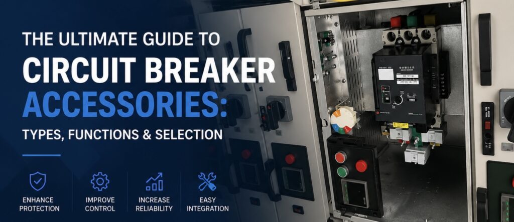
คำตอบด่วน: อุปกรณ์เสริมของเซอร์กิตเบรกเกอร์คืออะไร?
ตามมาตรฐาน IEC 60947-2 (มาตรฐานสากลที่ควบคุมสวิตช์เกียร์และชุดควบคุมแรงดันต่ำ) หน้าที่หลักของเบรกเกอร์วงจรคือการทำงานอย่างปลอดภัยในการเปิด ปิด และตัดกระแสไฟฟ้าในสภาวะปกติและผิดปกติที่กำหนด อย่างไรก็ตาม เบรกเกอร์เปล่าเป็นเพียงสวิตช์กลไกแยกส่วน อุปกรณ์เสริมเบรกเกอร์วงจรเป็นส่วนประกอบเสริมแบบโมดูลาร์ที่ได้มาตรฐานซึ่งออกแบบมาเพื่อเสริม MCCB, MCB และ ACB
แม้ว่าอุปกรณ์เหล่านี้จะไม่ตัดกระแสฟอลต์หลักด้วยตัวเอง แต่ถูกติดตั้งภายใน (เช่น สวิตช์ช่วยและชุดทริป) หรือภายนอก (เช่น กลไกมอเตอร์และมือหมุน) เพื่อขยายขีดความสามารถของเบรกเกอร์ในสี่มิติสำคัญ ได้แก่ การป้องกันขั้นสูง การควบคุมระยะไกล การส่งสัญญาณสถานะ และการปรับปรุงกลไก.
คุณค่าเชิงกลยุทธ์: พูดง่ายๆ คือ เซอร์กิตเบรกเกอร์ยังคงเป็นกล้ามเนื้อกลไกหลัก แต่อุปกรณ์เสริมทำหน้าที่เป็นระบบประสาทอัจฉริยะ ปัจจุบัน ทันทีที่เกิดฟอลต์ สวิตช์แจ้งเตือนจะส่งแพ็กเก็ตข้อมูลระยะไกลไปยังห้องควบคุมทันที ขณะที่กลไกมอเตอร์ช่วยให้วิศวกรแยกหรือรีเซ็ตสายจากระยะไกลได้อย่างปลอดภัย การผสานรวมนี้ลดเวลาเฉลี่ยในการซ่อมแซม (MTTR) ลง 85% และทำให้โรงงานปฏิบัติตามมาตรฐานโครงข่ายไฟฟ้าอัตโนมัติสมัยใหม่อย่างครบถ้วน.
อุปกรณ์เสริมเซอร์กิตเบรกเกอร์ทั่วไป
| ชื่ออุปกรณ์เสริม | ตัวย่อ | หน้าที่ |
| ชันต์ทริป | MX | ช่วยให้ตัดวงจรจากระยะไกลผ่านสัญญาณไฟฟ้า. |
| หน้าสัมผัสช่วย | AX / OF | แสดงสถานะ เปิด / ปิด ของเบรกเกอร์. |
| หน้าสัมผัสแจ้งเตือน | AL / SD | แสดงว่าเบรกเกอร์ทริปเนื่องจากฟอลต์หรือไม่. |
| อันเดอร์โวลเตจทริป | MN / UVT | ตัดวงจรเบรกเกอร์อัตโนมัติเมื่อแรงดันตก. |
| กลไกการทำงานด้วยมอเตอร์ | MOM / MO | ช่วยให้ปิดและเปิดด้วยมอเตอร์จากระยะไกล. |
| การเชื่อมต่อด้านหน้า | FC | การเดินสายมาตรฐานจากขั้วด้านหน้า. |
| การเชื่อมต่อด้านหลัง | RC | การเดินสายจากด้านหลังเพื่อประหยัดพื้นที่ภายในตู้. |
| มือหมุน | – | ช่วยให้สับสวิตช์ด้วยมือได้ปลอดภัยขึ้นนอกประตูตู้. |
ทำไมอุปกรณ์เสริมของเซอร์กิตเบรกเกอร์จึงสำคัญ?
ในโครงสร้างพื้นฐานทางอุตสาหกรรมและพาณิชย์สมัยใหม่ เซอร์กิตเบรกเกอร์มาตรฐานให้ “กล้ามเนื้อ” พื้นฐาน ซึ่งคือความสามารถเชิงกลดิบในการตัดกระแสไฟฟ้าระหว่างเกิดฟอลต์รุนแรง อย่างไรก็ตาม เบรกเกอร์เปล่าเปลือยทำงานเป็นชิ้นส่วนที่แยกตัว อุปกรณ์เสริมต่างหากที่ให้ “สมอง” และ “ระบบประสาท” แก่การติดตั้งไฟฟ้าทั้งหมด.
- การติดตั้งเซอร์กิตเบรกเกอร์ด้วยอุปกรณ์เสริมที่เหมาะสมเป็นความจำเป็นเชิงปฏิบัติการที่สำคัญด้วยเหตุผลชี้ขาดหลายประการ:
- การเพิ่มความปลอดภัยให้บุคลากรภาคสนาม: สภาพแวดล้อมกำลังสูงมีความเสี่ยงจากอาร์กแฟลชโดยธรรมชาติ อุปกรณ์เสริมเช่นกลไกมอเตอร์และมือหมุนแบบยืดช่วยเขียนโปรโตคอลความปลอดภัยหน้างานใหม่ทั้งหมด โดยให้ผู้ปฏิบัติงานสับสวิตช์ รีเซ็ต หรือถอดเบรกเกอร์ออกจากระยะปลอดภัย ไม่ว่าจะอยู่นอกประตูตู้ที่ล็อกอยู่หรือจากห้องควบคุมส่วนกลางระยะไกล.
- การลดเวลาหยุดผลิตที่มีค่าใช้จ่ายสูง: เมื่อสายการผลิตสำคัญหยุดกะทันหัน ทุกวินาทีคือรายได้ที่สูญเสีย หากไม่มีอุปกรณ์เสริม ทีมบำรุงรักษาต้องทดสอบสายด้วยมือเพื่อสรุป ว่าเหตุใด เบรกเกอร์จึงเปิดวงจร การใช้หน้าสัมผัสช่วยและหน้าสัมผัสแจ้งเตือนช่วยให้เบรกเกอร์ส่งข้อมูลระยะไกลที่แม่นยำไปยังระบบ PLC หรือ SCADA ของคุณทันที โดยแยกความแตกต่างระหว่างการปิดด้วยมือตามปกติกับการทริปจากไฟฟ้าลัดวงจรรุนแรงในหน่วยมิลลิวินาที.
- การปกป้องทรัพย์สินเชิงรุกต่อปัญหาคุณภาพไฟฟ้า: ในขณะที่เบรกเกอร์มาตรฐานตอบสนองต่อโหลดเกิน เครื่องจักรสมัยใหม่ (เช่น ศูนย์ CNC เซิร์ฟเวอร์ข้อมูล และมอเตอร์งานหนัก) มีความเปราะบางสูงต่อความผันผวนของไฟฟ้าที่ละเอียดอ่อนกว่า ชุดปลดแรงดันต่ำ (UVR) ทำหน้าที่เป็นผู้พิทักษ์เชิงรุก โดยปลดเบรกเกอร์ระหว่างแรงดันตกคร่อมรุนแรง (แรงดันตกชั่วขณะ) ก่อนที่แรงดันต่ำจะทำให้ขดลวดมอเตอร์ราคาแพงร้อนเกินไปและไหม้เสียหาย.
- การรับรองการปฏิบัติตามมาตรฐานสากลและการเพิ่มประสิทธิภาพพื้นที่: มาตรฐานสากลเช่น IEC 61439 กำหนดข้อบังคับที่เข้มงวดเกี่ยวกับระยะห่างทางไฟฟ้า การแยกส่วน และการป้องกันการบุกรุก (ระดับ IP) อุปกรณ์เสริมเชิงโครงสร้าง เช่น ชุดเชื่อมต่อด้านหลังและแผ่นป้องกันขั้วต่อ ช่วยให้ผู้สร้างตู้แผงสามารถเดินสายเคเบิลขนาดใหญ่ได้อย่างมีประสิทธิภาพ รับรองการปฏิบัติตามอย่างครบถ้วนพร้อมลดพื้นที่ทางกายภาพของตู้สวิตช์ได้สูงสุด 35%.
บรรทัดสุดท้าย: การลงทุนในเบรกเกอร์คุณภาพพรีเมียมแต่ประหยัดอุปกรณ์เสริม ก็เหมือนการซื้อยานพาหนะสมรรถนะสูงที่ไม่มีแผงหน้าปัดหรือกระจกมองข้าง อุปกรณ์เสริมของเบรกเกอร์มีความสำคัญเพราะเปลี่ยนการป้องกันทางไฟฟ้าขั้นพื้นฐานให้กลายเป็นความต่อเนื่องในการดำเนินงาน การบำรุงรักษาที่คาดการณ์ได้ และความอุ่นใจอย่างแท้จริงหน้างาน.
ประเภทหลักของอุปกรณ์เสริมเบรกเกอร์
เพื่อสร้างเครือข่ายการจ่ายไฟฟ้าแรงดันต่ำที่เป็นอัตโนมัติสูงและเป็นไปตามข้อกำหนด มาตรฐานอุตสาหกรรมจัดประเภทอุปกรณ์เสริมเบรกเกอร์ออกเป็นสามหมวดการทำงานหลักตามการติดตั้งทางกายภาพและบทบาทการทำงานภายในระบบ:
ส่วนประกอบเหล่านี้ติดตั้งอยู่ภายในช่องภายในเฉพาะภายในตัวเรือนเบรกเกอร์ โดยเชื่อมต่อโดยตรงกับกลไกภายในของเบรกเกอร์เพื่อให้ข้อมูลเทเลเมทรีหรือดำเนินการปลดวงจรเพื่อความปลอดภัยอัตโนมัติ.
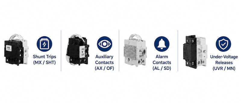
ชุดปลดวงจรด้วยสัญญาณภายนอก (MX / SHT):
ตัวช่วยให้การแยกวงจรฉุกเฉินระยะไกลเป็นไปได้ เมื่อได้รับพลังงานจากแหล่งแรงดันภายนอก (เช่น สัญญาณแจ้งเตือนอัคคีภัยหรือปุ่มหยุดฉุกเฉิน) ชุดปลดวงจรจะบังคับให้กลไกล็อกของเบรกเกอร์เปิดทันที.
หน้าสัมผัสเสริม (AX / OF):
ทำหน้าที่เป็น “ดวงตา” ของระบบอัตโนมัติของคุณ โดยสะท้อนสถานะทางกายภาพของหน้าสัมผัสหลักของเบรกเกอร์ ส่งสัญญาณ “เปิด” หรือ “ปิด” แบบเรียลไทม์ไปยัง PLC ระบบ SCADA หรือไฟแสดงสถานะบนประตูตู้แผง.
หน้าสัมผัสสัญญาณเตือน (AL / SD):
อุปกรณ์เหล่านี้คือสวิตช์เฉพาะทางที่ เท่านั้น จะทำงานเมื่อเบรกเกอร์ตัดวงจรเนื่องจากความผิดปกติทางไฟฟ้า (โหลดเกิน ไฟฟ้าลัดวงจร หรือไฟรั่วลงดิน) ช่วยให้ทีมบำรุงรักษาสามารถแยกแยะการตัดวงจรจากอันตรายออกจากการปิดด้วยมือตามปกติได้ทันที.
ขดลวดปลดวงจรแรงดันต่ำ (UVR / MN):
ขดลวดปลดวงจรแรงดันต่ำ (UVR / MN): อุปกรณ์เฝ้าระวังคุณภาพแรงดันไฟฟ้าเชิงรุก จะตัดวงจรเบรกเกอร์โดยอัตโนมัติหากแรงดันไฟฟ้าขาเข้าลดลงต่ำกว่าเกณฑ์วิกฤต (โดยทั่วไปคือ 35% – 70% ของแรงดันพิกัด) ปกป้องมอเตอร์ปลายทางไม่ให้ไหม้ระหว่างแรงดันตกอย่างรุนแรง.
นอกเหนือจากชิ้นส่วนภายในแล้ว อุปกรณ์เสริมที่จำเป็นบางชนิดยังติดตั้งภายนอกที่ด้านหน้าหรือด้านข้างของเบรกเกอร์ โมดูลเหล่านี้เปลี่ยนแปลงวิธีการทำงานของอุปกรณ์โดยพื้นฐาน เปลี่ยนระบบของคุณจากการสับสวิตช์ด้วยมือแบบพื้นฐานไปสู่ระบบอัตโนมัติ PLC ขั้นสูง หรือการควบคุมด้วยมือผ่านประตูตู้ที่มีความปลอดภัยสูง.
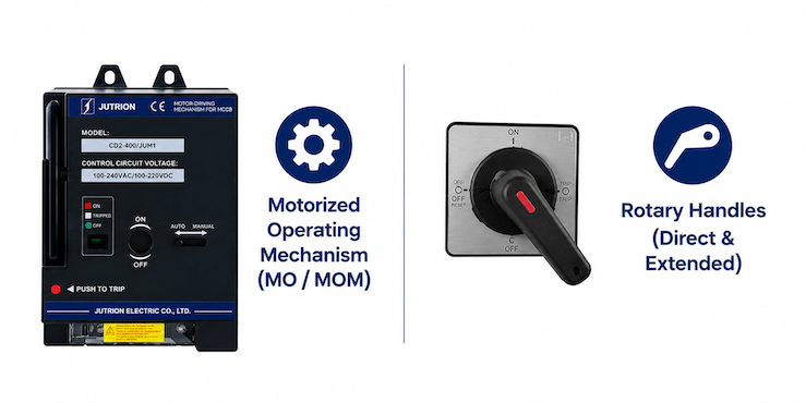
กลไกการทำงานด้วยมอเตอร์(MO / MOM):
ชุดมอเตอร์เฉพาะทางเหล่านี้ติดตั้งโดยตรงที่ด้านหน้าของเบรกเกอร์ลูกเซอร์กิตแบบขึ้นรูป (MCCBs) เพื่อขับเคลื่อนระบบสับสวิตช์ภายในโดยอัตโนมัติ ด้วยการแปลงคำสั่งไฟฟ้าระยะไกลให้เป็นแรงกลที่เชื่อถือได้ อุปกรณ์เหล่านี้ผสานรวมกับตัวควบคุมลอจิกแบบโปรแกรมได้ (PLCs) ได้อย่างราบรื่นผ่านโปรโตคอลการสื่อสาร RS485 (เช่น Modbus RTU) นี่คือเทคโนโลยีที่ปลดล็อกการตัดวงจรอัตโนมัติ การรีเซ็ตระยะไกล และการจัดการกริดแบบรวมศูนย์เต็มรูปแบบจากห้องควบคุมโดยตรง.
มือหมุนโรตารี (แบบตรงและแบบต่อแกน):
คันสับสวิตช์มาตรฐานของเบรกเกอร์อาจแข็งและเป็นอันตรายเมื่อใช้งานโดยตรงภายใต้โหลด มือหมุนโรตารีแบบตรงให้ความได้เปรียบเชิงกลทำให้สับง่ายขึ้น ในขณะที่มือหมุนโรตารีแบบต่อแกนใช้เพลาเพื่อให้ผู้ปฏิบัติงานสามารถสับเบรกเกอร์ได้อย่างปลอดภัยจากภายนอกประตูตู้ที่ปิดอยู่ โดยคงการป้องกันฝุ่นและน้ำระดับ IP40/IP54.
สำหรับการติดตั้งทางกายภาพ คุณต้องพิจารณาด้วยว่าเบรกเกอร์เชื่อมต่อกับโครงสร้างตู้สวิตช์อย่างไร เบรกเกอร์แบบเสียบปลั๊กสามารถกำหนดค่าให้มีฐานเชื่อมต่อด้านหน้าหรือฐานเชื่อมต่อด้านหลังตามผังตู้ ทิศทางการเดินสาย และข้อกำหนดการบำรุงรักษา ทั้งสองรูปแบบช่วยให้ถอดและเปลี่ยนเบรกเกอร์ได้โดยไม่ต้องถอดสายตัวนำหลักออกจากฐาน.
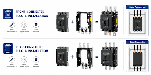
การติดตั้งแบบเสียบปลั๊กเชื่อมต่อด้านหน้า
เบรกเกอร์แบบเสียบปลั๊กเชื่อมต่อด้านหน้าติดตั้งบนฐานเสียบปลั๊กเฉพาะ โดยสายเคเบิลหรือบัสบาร์ของวงจรหลักเชื่อมต่อกับขั้วต่อด้านหน้าของฐาน เบรกเกอร์สามารถถอดและเปลี่ยนได้โดยไม่ต้องถอดสายตัวนำหลัก ช่วยให้การบำรุงรักษาง่ายขึ้นและลดเวลาในการเปลี่ยน.
การติดตั้งแบบเสียบปลั๊กเชื่อมต่อด้านหลัง
เบรกเกอร์แบบเสียบปลั๊กเชื่อมต่อด้านหลังติดตั้งบนฐานเสียบปลั๊กเฉพาะเช่นกัน แต่วงจรหลักเชื่อมต่อจากด้านหลังแผ่นยึดผ่านขั้วต่อด้านหลังหรือแท่งเชื่อมต่อ การจัดวางแบบนี้ให้ฟังก์ชันการเปลี่ยนที่สะดวกเช่นเดียวกัน ในขณะที่ทำให้ผังตู้ด้านหน้าเป็นระเบียบมากขึ้นและลดการรบกวนกับสายไฟด้านหน้า.
ทั้งสองรูปแบบรองรับการเปลี่ยนเบรกเกอร์ที่รวดเร็วยิ่งขึ้น ความแตกต่างหลักอยู่ที่ว่าวงจรหลักเชื่อมต่อกับขั้วต่อด้านหน้าหรือด้านหลังของฐานเสียบปลั๊ก.
วิธีเลือกอุปกรณ์เสริมเบรกเกอร์ที่เหมาะสม
ในโครงการไฟฟ้าแรงดันต่ำจริง เรามักพบความท้าทายเดียวกันในหมู่ผู้สร้างตู้ไฟ ผู้รวมระบบ และวิศวกรโครงการ พวกเขารู้ว่า MCCB, MCB หรือ ACB อาจต้องใช้อุปกรณ์เสริมเพื่อรองรับการควบคุมระยะไกล การแสดงสถานะ การแจ้งเตือนข้อผิดพลาด หรือการใช้งานที่ติดตั้งบนประตู แต่พวกเขามักไม่แน่ใจว่าจะเลือกการกำหนดค่าอุปกรณ์เสริมที่ถูกต้องอย่างไร
การพึ่งพาเฉพาะคู่มือผลิตภัณฑ์ที่ซับซ้อนโดยไม่ยืนยันโครงสร้างตู้จริงและข้อกำหนดการควบคุม อาจนำไปสู่ปัญหาการติดตั้งที่มีค่าใช้จ่ายสูง เช่น การเลือกแรงดันควบคุมผิดสำหรับชุดปลดด้วยแรงดันอาจทำให้คอยล์เสียหาย การสับสนระหว่างหน้าสัมผัสช่วยกับหน้าสัมผัสสัญญาณเตือนอาจทำให้การป้อนกลับสถานะผิดพลาด และการละเลยผังขั้วต่อหรือพื้นที่ติดตั้งอาจส่งผลต่อการเดินสาย ระยะห่างทางไฟฟ้า และการบำรุงรักษาในอนาคต.
นั่นคือเหตุผลที่ไม่ควรเลือกอุปกรณ์เสริมของเซอร์กิตเบรกเกอร์จากชื่อเพียงอย่างเดียว การเลือกที่ถูกต้องควรพิจารณารุ่นของเบรกเกอร์ ขนาดเฟรม แรงดันควบคุม วิธีการติดตั้ง ข้อกำหนดสัญญาณ และสภาพแวดล้อมการใช้งานจริง.
เพื่อให้กระบวนการที่ซับซ้อนนี้ง่ายขึ้นและปกป้องการลงทุนทางวิศวกรรมของคุณ ผมได้สรุปเกณฑ์การเลือกหลักเป็นขั้นตอนที่ปฏิบัติได้จริงและชัดเจน มาดูกันว่าคุณจะกำหนดชุดอุปกรณ์เสริมที่เหมาะสมสำหรับการติดตั้งครั้งต่อไปได้อย่างแม่นยำอย่างไร.
ขั้นตอนที่ 1: ยืนยันประเภท รุ่น และขนาดเฟรมของเซอร์กิตเบรกเกอร์
ขั้นตอนแรกคือการระบุแพลตฟอร์มเซอร์กิตเบรกเกอร์ที่แน่นอนที่จะติดตั้งอุปกรณ์เสริม อุปกรณ์เสริมของเซอร์กิตเบรกเกอร์โดยทั่วไปไม่สามารถใช้ร่วมกันได้ทั้งหมด แม้เซอร์กิตเบรกเกอร์สองตัวจะมีกระแสพิกัดเท่ากัน ความแตกต่างในซีรีส์ผลิตภัณฑ์ ขนาดเฟรม การจัดขั้ว กลไกการทำงานภายใน และขนาดการติดตั้ง อาจทำให้อุปกรณ์เสริมใช้ร่วมกันไม่ได้.
ก่อนเลือกอุปกรณ์เสริมใดๆ ให้ยืนยันข้อมูลต่อไปนี้:
- ประเภทเซอร์กิตเบรกเกอร์: MCB, MCCB หรือ ACB
- ผู้ผลิตและซีรีส์ผลิตภัณฑ์
- รุ่นเซอร์กิตเบรกเกอร์แบบเต็ม
- จำนวนขั้ว: 1P, 2P, 3P หรือ 4P
- ขนาดเฟรม เช่น 100A, 250A หรือ 400A
ตัวอย่างเช่น ชุดปลดด้วยแรงดันที่ออกแบบสำหรับ MCCB ขนาด 100AF อาจไม่พอดีกับเบรกเกอร์ขนาด 250AF แม้เซอร์กิตเบรกเกอร์ทั้งสองจะทำงานที่กระแสพิกัดเดียวกัน ขนาดเชิงกล คลิปยึด ระยะชักการทำงาน และตำแหน่งขั้วต่ออาจแตกต่างกันโดยสิ้นเชิง.
ดังนั้น ควรตรวจสอบรุ่นและขนาดเฟรมของเซอร์กิตเบรกเกอร์กับตารางความเข้ากันได้ของอุปกรณ์เสริมที่ผู้ผลิตจัดทำไว้เสมอ.
เคล็ดลับเชิงปฏิบัติ: อย่าเลือกอุปกรณ์เสริมจากกระแสพิกัดของเบรกเกอร์เพียงอย่างเดียว ควรระบุหมายเลขรุ่นแบบเต็มหรือภาพถ่ายป้ายชื่อเบรกเกอร์ที่ชัดเจนเสมอเมื่อขอใบเสนอราคา.
ขั้นตอนที่ 2: จับคู่อุปกรณ์เสริมกับงานใช้งานที่ต้องการ
หลังจากยืนยันรุ่นเซอร์กิตเบรกเกอร์แล้ว ขั้นตอนถัดไปไม่ใช่เพียงเลือกอุปกรณ์เสริมตามชื่อ แต่ต้องระบุข้อกำหนดการควบคุม การป้องกัน หรือการส่งสัญญาณที่แท้จริงของระบบไฟฟ้า อุปกรณ์เสริมต่างชนิดอาจใช้ร่วมกันได้ แต่แต่ละชนิดถูกออกแบบมาเพื่อแก้ข้อกำหนดการใช้งานเฉพาะ การเลือกที่ถูกต้องจึงควรเริ่มจากคำถาม: ระบบต้องการให้เซอร์กิตเบรกเกอร์ทำอะไร?
จากประสบการณ์หลายปีในการนำโครงการวิศวกรรมอุตสาหกรรม ผมเคยเห็นทีมงานข้ามขั้นตอนสำคัญนี้และเลือกอุปกรณ์เสริมจากแคตตาล็อกอย่างมั่วซั่วตามชื่อเพียงอย่างเดียว สิ่งนี้มักนำไปสู่ความโกลาหลระหว่างการทดสอบระบบ เช่น การสับสนระหว่างหน้าสัมผัสช่วยกับหน้าสัมผัสสัญญาณเตือน ซึ่งทำให้ PLC ส่วนกลางไม่สามารถทราบได้เลยว่าการปลดวงจรเป็นความผิดพร่องด้านความปลอดภัยหรือเป็นเพียงการสั่งงานด้วยมือ.
เพื่อหลีกเลี่ยงข้อผิดพลาดภาคสนามที่มีค่าใช้จ่ายสูงเหล่านี้ มาดูกันว่าข้อกำหนดของระบบเฉพาะเจาะจงกำหนดการเลือกส่วนประกอบของคุณอย่างไร
- หากเบรกเกอร์ต้องถูกตัดวงจรจากระยะไกลโดยระบบสัญญาณเตือนอัคคีภัยหรือวงจรหยุดฉุกเฉิน โดยปกติจำเป็นต้องใช้ชันต์ทริป.
- หากเบรกเกอร์ต้องเปิดวงจรหรือป้องกันการปิดวงจรเมื่อแรงดันควบคุมลดลงต่ำกว่าระดับที่กำหนด อันเดอร์โวลเทจรีลีสจะเหมาะสมกว่า.
- หากระบบควบคุมจำเป็นต้องทราบว่าเบรกเกอร์อยู่ในสถานะ ON หรือ OFF ควรเลือกใช้หน้าสัมผัสเสริม.
- หากระบบจำเป็นต้องแยกความแตกต่างระหว่างการทริปจากการป้องกันกับการเปิดวงจรด้วยมือ จำเป็นต้องใช้หน้าสัมผัสสัญญาณเตือน.
- หากเบรกเกอร์ต้องถูกเปิดหรือปิดจากระยะไกล อาจจำเป็นต้องใช้มอเตอร์โอเปอเรเตอร์.
- หากเบรกเกอร์ต้องถูกควบคุมจากภายนอกประตูตู้ ควรเลือกใช้ด้ามจับแบบหมุน.
- หากเบรกเกอร์จำเป็นต้องถูกถอดหรือเปลี่ยนอย่างรวดเร็วโดยไม่ต้องถอดสายไฟหลักหรือบัสบาร์ทั้งหมด การกำหนดค่าแบบปลั๊กอินอาจเหมาะสมกว่า.
ควรเลือกอุปกรณ์เสริมตามฟังก์ชันที่ต้องการมากกว่ารูปลักษณ์หรือชื่อผลิตภัณฑ์ทั่วไป.
ขั้นตอนที่ 3: จับคู่แรงดันควบคุมและประเภทของแหล่งจ่ายไฟ
แรงดันควบคุมเป็นหนึ่งในพารามิเตอร์ที่สำคัญที่สุดเมื่อเลือกอุปกรณ์เสริมที่ทำงานด้วยไฟฟ้า ชันต์ทริป อันเดอร์โวลเทจรีลีส คอยล์ปิดวงจร และมอเตอร์โอเปอเรเตอร์ได้รับการออกแบบสำหรับช่วงแรงดันเฉพาะ.
- แรงดันควบคุมทั่วไปประกอบด้วย:
- AC 24V, 36V, 48V, 110V, 220V, 230V, หรือ 380V
- DC 24V, 36V, 48V, 110V, 125V, หรือ 220V
อุปกรณ์เสริมที่เลือกต้องตรงกับทั้งระดับแรงดันไฟฟ้าและประเภทแหล่งจ่ายไฟ ตัวอย่างเช่น ชันต์ทริป AC 220V ไม่ควรต่อกับวงจรควบคุม DC 220V แม้ว่าค่าแรงดันไฟฟ้าจะเท่ากัน แต่โครงสร้างขดลวดและลักษณะทางไฟฟ้าแตกต่างกัน แหล่งจ่ายไฟที่ไม่ถูกต้องอาจทำให้ไม่สามารถทำงานได้ ความร้อนสูงเกินไป ขดลวดเสียหาย หรือการทริปที่ไม่น่าเชื่อถือ.
ก่อนยืนยันอุปกรณ์เสริม ตรวจสอบสิ่งต่อไปนี้:
- แหล่งจ่ายควบคุมเป็น AC หรือ DC
- แรงดันควบคุมที่กำหนด
- ช่วงแรงดันไฟฟ้าที่อนุญาตให้ใช้งาน
- สัญญาณเป็นแบบต่อเนื่องหรือชั่วขณะ
- อุปกรณ์เสริมยังคงได้รับพลังงานระหว่างการทำงานปกติหรือไม่
สำคัญ: อันเดอร์โวลเทจรีลีสมักได้รับพลังงานอย่างต่อเนื่องขณะที่เซอร์กิตเบรกเกอร์ทำงาน ดังนั้นวงจรควบคุมต้องจ่ายไฟที่เสถียรและมีความจุขดลวดเพียงพอ.
แหล่งจ่ายไฟของมอเตอร์โอเปอเรเตอร์: โดยปกติมอเตอร์โอเปอเรเตอร์ควรได้รับพลังงานจากด้านไลน์ของเซอร์กิตเบรกเกอร์หรือจากแหล่งจ่ายไฟควบคุมอิสระ หากได้รับพลังงานจากด้านโหลด อาจสูญเสียพลังงานหลังจากเบรกเกอร์เปิดหรือทริป ทำให้ไม่สามารถปิดระยะไกลหรือรีเซ็ตในภายหลังได้.
การปรับแต่ง: แรงดันควบคุมของมอเตอร์โอเปอเรเตอร์สามารถปรับแต่งได้ตามแหล่งจ่ายไฟและข้อกำหนดของโครงการของลูกค้า.
ขั้นตอนที่ 4: ตรวจสอบตำแหน่งการติดตั้งและความเข้ากันได้ของอุปกรณ์เสริม
MCB และ MCCB หลายรุ่นมีตำแหน่งหรือตำแหน่งติดตั้งที่กำหนดไว้สำหรับอุปกรณ์เสริมภายใน จำนวน ตำแหน่ง และการรวมอุปกรณ์เสริมที่เข้ากันได้อาจแตกต่างกันไปขึ้นอยู่กับซีรีส์ผลิตภัณฑ์ ขนาดเฟรม และการกำหนดขั้ว
ก่อนสั่งซื้อ ยืนยันสิ่งต่อไปนี้:
- อุปกรณ์เสริมติดตั้งภายในหรือภายนอก
- ติดตั้งด้านซ้ายหรือด้านขวา
- หนึ่งช่องสามารถรับโมดูลคอนแทคได้มากกว่าหนึ่งหรือไม่
- อุปกรณ์เสริมที่เลือกสามารถติดตั้งร่วมกันได้หรือไม่
- ต้องใช้เทอร์มินัลบล็อกหรือสายไฟเพิ่มเติมหรือไม่
MCCB บางรุ่น โดยเฉพาะ MCCB ป้องกันกระแสรั่ว มีพื้นที่ภายในจำกัดสำหรับอุปกรณ์เสริม ในบางรุ่นมีตำแหน่งอุปกรณ์เสริมภายในเพียงตำแหน่งเดียว ดังนั้นชันต์ทริปมาตรฐานและ auxiliary contact แยกต่างหากจึงไม่สามารถติดตั้งพร้อมกันได้อย่างอิสระ ในสถานการณ์นี้ อาจเลือกโมดูลชันต์ทริปและ auxiliary contact แบบรวมเมื่อต้องการทั้งการทริประยะไกลและการตอบกลับตำแหน่งเบรกเกอร์ การจัดเรียงการติดตั้งอุปกรณ์เสริมอาจแตกต่างกันระหว่างซีรีส์ MCCB ต่างๆ ตัวอย่างเช่น ชันต์ทริปอาจติดตั้งด้านซ้ายในรุ่นหนึ่งแต่ด้านขวาในอีกรุ่นหนึ่ง ในขณะที่ auxiliary contact หรือ alarm contact อาจ occupy ตำแหน่งที่กำหนดแตกต่างกัน.
ดังนั้น ความเข้ากันได้ของอุปกรณ์เสริมไม่สามารถกำหนดได้เพียงจากชื่ออุปกรณ์เสริมหรือกระแสพิกัดของเบรกเกอร์ ต้องยืนยันซีรีส์ MCCB ที่แน่นอน ขนาดเฟรม ฟังก์ชันป้องกันกระแสรั่ว การกำหนดขั้ว และเลย์เอาต์อุปกรณ์เสริมภายในก่อนสั่งซื้อ.
เคล็ดลับเชิงปฏิบัติ: หาก MCCB มีช่องอุปกรณ์เสริมเพียงช่องเดียว ตรวจสอบว่ามีโมดูลอุปกรณ์เสริมแบบรวม เช่น ชันต์ทริปพร้อม auxiliary contact สำหรับซีรีส์เบรกเกอร์นั้นหรือไม่.
การเลือกอุปกรณ์เสริมเซอร์กิตเบรกเกอร์ที่ถูกต้องต้องมากกว่าการระบุชื่ออุปกรณ์เสริม ต้องยืนยันรุ่นเบรกเกอร์ ขนาดเฟรม ฟังก์ชันที่ต้องการ แรงดันควบคุม ตำแหน่งการติดตั้ง และความเข้ากันได้ของอุปกรณ์เสริมร่วมกันทั้งหมด การกำหนดค่าที่ถูกต้องควรตอบสนองทั้งข้อกำหนดการควบคุมทางไฟฟ้าและเงื่อนไขการติดตั้งตู้จริง.
ขั้นตอนที่ 5: ตัวเลือกการติดตั้งและการเชื่อมต่อเซอร์กิตเบรกเกอร์แบบปลั๊กอิน
นอกเหนือจากฟังก์ชันทางไฟฟ้า วิธีการติดตั้งและการเชื่อมต่อของเซอร์กิตเบรกเกอร์ยังสามารถส่งผลต่อการเลือกอุปกรณ์เสริมได้ การกำหนดค่าปลั๊กอินที่แตกต่างกันอาจต้องใช้ฐาน เทอร์มินัล การจัดเรียงการติดตั้ง และโครงสร้างตู้ที่แตกต่างกัน.
การติดตั้งแบบเสียบปลั๊กเชื่อมต่อด้านหน้า:
เซอร์กิตเบรกเกอร์แบบปลั๊กอินเชื่อมต่อด้านหน้าติดตั้งบนฐานปลั๊กอินเฉพาะ โดยเชื่อมต่อสายวงจรหลักหรือบัสบาร์จากด้านหน้า สามารถถอดและเปลี่ยนเบรกเกอร์ได้โดยไม่ต้องถอดสายตัวนำวงจรหลักออกจากฐาน ช่วยลดเวลาบำรุงรักษา.
การติดตั้งแบบเสียบปลั๊กเชื่อมต่อด้านหลัง:
เซอร์กิตเบรกเกอร์แบบปลั๊กอินเชื่อมต่อด้านหลังก็ติดตั้งบนฐานปลั๊กอินเฉพาะเช่นกัน แต่วงจรหลักเชื่อมต่อจากด้านหลังแผ่นติดตั้งผ่านเทอร์มินัลด้านหลังหรือแถบเชื่อมต่อ ให้ฟังก์ชันการเปลี่ยนที่สะดวกเช่นเดียวกันพร้อมรองรับเลย์เอาต์ตู้ด้านหน้าที่สะอาดกว่า.
ทั้งสองการกำหนดค่ารองรับการเปลี่ยนเบรกเกอร์ที่รวดเร็วขึ้น ความแตกต่างหลักคือทิศทางการเชื่อมต่อวงจรหลักและข้อกำหนดเลย์เอาต์ตู้ที่เกี่ยวข้อง.
รายการตรวจสอบการเลือกอุปกรณ์เสริมเซอร์กิตเบรกเกอร์
| รายการคัดเลือก | สิ่งที่ต้องยืนยัน |
|---|---|
| ประเภทเซอร์กิตเบรกเกอร์ | MCB, MCCB, MCCB ป้องกันกระแสรั่ว หรือ ACB |
| ผู้ผลิตและซีรีส์ | ซีรีส์ผลิตภัณฑ์ ครบถ้วน |
| รุ่น ครบถ้วน | หมายเลขรุ่นเซอร์กิตเบรกเกอร์ ครบถ้วน |
| ขนาดเฟรม | 100AF, 250AF, 400AF เป็นต้น. |
| จำนวนขั้ว | 1P, 2P, 3P หรือ 4P |
| ฟังก์ชันที่ต้องการ | ทริประยะไกล ป้องกันอันเดอร์โวลเทจ ตอบกลับสถานะ แจ้งเตือนข้อผิดพลาด ทำงานระยะไกล หรืออินเทอร์ล็อก |
| แรงดันควบคุม | แรงดันพิกัดและประเภทแหล่งจ่าย AC/DC |
| สัญญาณการทำงาน | ต่อเนื่องหรือชั่วขณะ |
| ตำแหน่งอุปกรณ์เสริม | ภายใน ภายนอก ด้านซ้าย หรือด้านขวา |
| การรวมอุปกรณ์เสริม | อุปกรณ์เสริมแยกหรือโมดูลรวม |
| วิธีการเชื่อมต่อ | การเชื่อมต่อด้านหน้าหรือการเชื่อมต่อด้านหลัง |
| วิธีการติดตั้ง | แบบติดตั้งคงที่หรือแบบเสียบ |
| สภาพตู้ | ความลึก พื้นที่เดินสาย ความยาวเพลา และระยะห่างสำหรับการบำรุงรักษา |
| เอกสารโครงการ | รูปถ่ายแผ่นป้ายชื่อ แผนผังการควบคุม แบบวาดตู้ และข้อกำหนดทางเทคนิค |
หากข้อมูลใดข้างต้นไม่แน่นอน ให้จัดหาแบบเบรกเกอร์ที่สมบูรณ์ รูปถ่ายแผ่นป้ายชื่อ และแบบวาดโครงการให้ซัพพลายเออร์ก่อนสั่งซื้อ.
ข้อผิดพลาดทั่วไปในการเลือกอุปกรณ์เสริมเบรกเกอร์วงจร
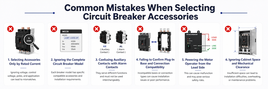
แม้แต่ผู้สร้างตู้ที่มีประสบการณ์และวิศวกรโครงการก็อาจเลือกอุปกรณ์เสริมผิดพลาดได้ เมื่อแบบเบรกเกอร์ แรงดันควบคุม โครงสร้างการติดตั้ง หรือข้อกำหนดสัญญาณไม่ได้รับการยืนยันอย่างครบถ้วน ต่อไปนี้คือปัญหาที่พบบ่อยที่สุดบางส่วนในการเลือกอุปกรณ์เสริมเบรกเกอร์วงจร.
เลือกอุปกรณ์เสริมตามกระแสพิกัดเท่านั้น
ไม่ควรเลือกอุปกรณ์เสริมเบรกเกอร์วงจรตามกระแสพิกัดของเบรกเกอร์เท่านั้น เบรกเกอร์สองตัวที่มีกระแสพิกัดเดียวกันอาจอยู่ในซีรีส์ผลิตภัณฑ์หรือขนาดโครงที่แตกต่างกัน และโครงสร้างภายใน ขนาดการติดตั้ง และตำแหน่งอุปกรณ์เสริมอาจแตกต่างกันโดยสิ้นเชิง.
วิธีหลีกเลี่ยง: ตรวจสอบแบบเบรกเกอร์ที่สมบูรณ์ ซีรีส์ผลิตภัณฑ์ ขนาดโครง และจำนวนขั้วเสมอ.
ละเลยแบบเบรกเกอร์วงจรที่สมบูรณ์
การให้ข้อมูลเพียงเช่น “250A MCCB” มักไม่เพียงพอที่จะระบุอุปกรณ์เสริมที่ถูกต้องได้ หมายเลขแบบที่สมบูรณ์อาจมีข้อมูลสำคัญเกี่ยวกับซีรีส์เบรกเกอร์ ขนาดโครง ความสามารถในการตัด องค์ประกอบขั้ว และประเภทการป้องกัน.
เรื่องนี้สำคัญอย่างยิ่งสำหรับ MCCB ที่มีการตรวจจับกระแสไฟรั่ว MCCB อิเล็กทรอนิกส์ และเบรกเกอร์ที่มีโครงสร้างภายในพิเศษ
วิธีหลีกเลี่ยง: ให้หมายเลขแบบที่สมบูรณ์หรือรูปถ่ายที่ชัดเจนของแผ่นป้ายชื่อเบรกเกอร์.
สับสนระหว่างคอนแทคเสริมกับคอนแทคสัญญาณเตือน
คอนแทคเสริมและคอนแทคสัญญาณเตือนต่างให้สัญญาณตอบกลับทางไฟฟ้า แต่บ่งชี้สภาวะที่แตกต่างกัน คอนแทคเสริมโดยปกติบ่งชี้ว่าเบรกเกอร์วงจรอยู่ในสถานะ ON หรือ OFF คอนแทคสัญญาณเตือนบ่งชี้ว่าเบรกเกอร์ได้ทริปเนื่องจากโอเวอร์โหลด ลัดวงจร หรือเหตุการณ์ป้องกันอื่น หากเลือกคอนแทคผิด PLC หรือระบบตรวจสอบอาจได้รับข้อมูลสถานะที่ไม่ถูกต้อง.
วิธีหลีกเลี่ยง: ยืนยันว่าระบบต้องการการตอบกลับตำแหน่งหรือการตอบกลับการทริปจากความผิดพลาด.
ไม่ยืนยันความเข้ากันได้ของฐานแบบเสียบและวิธีการเชื่อมต่อ
ฐานแบบเสียบต้องตรงกับซีรีส์เบรกเกอร์ ขนาดโครง จำนวนขั้ว และวิธีการเชื่อมต่อที่แน่นอน การกำหนดค่าแบบเสียบที่เชื่อมต่อด้านหน้าและด้านหลังอาจใช้ฐาน ขั้วต่อ แท่งเชื่อมต่อ และโครงสร้างตู้ที่แตกต่างกัน ฐานที่เลือกตามกระแสพิกัดเท่านั้นอาจไม่พอดีกับเบรกเกอร์อย่างถูกต้อง.
วิธีหลีกเลี่ยง: ยืนยันว่าระบบต้องการการกำหนดค่าแบบเสียบที่เชื่อมต่อด้านหน้าหรือด้านหลังก่อนสั่งซื้อ.
จ่ายไฟให้มอเตอร์โอเปอเรเตอร์จากด้านโหลด
หากมอเตอร์โอเปอเรเตอร์ได้รับไฟจากด้านโหลดของเบรกเกอร์วงจร อาจสูญเสียไฟหลังจากเบรกเกอร์เปิดหรือทริป ซึ่งอาจทำให้ไม่สามารถปิดหรือรีเซ็ตเบรกเกอร์จากระยะไกลได้.
วิธีหลีกเลี่ยง: โดยปกติมอเตอร์โอเปอเรเตอร์ควรได้รับไฟจากด้านสายของเบรกเกอร์หรือจากแหล่งจ่ายไฟควบคุมอิสระ ตามการออกแบบระบบ.
6.ละเลยพื้นที่ตู้และระยะห่างทางกล
แม้ว่าอุปกรณ์เสริมจะเข้ากันได้ทางไฟฟ้า แต่ก็อาจยังไม่สามารถติดตั้งได้หากพื้นที่ตู้ไม่เพียงพอ มอเตอร์โอเปอเรเตอร์ มือหมุน ฐานแบบเสียบ ขั้วต่อด้านหลัง ฝาครอบขั้วต่อ และหางปลาสายเคเบิล ล้วนต้องใช้พื้นที่ติดตั้งเพิ่มเติม ระยะห่างที่ไม่เพียงพออาจส่งผลต่อการเดินสาย การปิดประตูตู้ การใช้งาน และการบำรุงรักษาในอนาคต.
วิธีหลีกเลี่ยง: ตรวจสอบแบบวาดตู้ ขนาดเบรกเกอร์ ขนาดอุปกรณ์เสริม การเดินสายเคเบิล และพื้นที่บำรุงรักษาก่อนยืนยันคำสั่งซื้อ.
ข้อผิดพลาดในการเลือกอุปกรณ์เสริมเบรกเกอร์วงจรส่วนใหญ่สามารถหลีกเลี่ยงได้โดยการยืนยันแบบเบรกเกอร์ที่สมบูรณ์ แรงดันควบคุม ฟังก์ชันที่ต้องการ เลย์เอาต์อุปกรณ์เสริมภายใน วิธีการติดตั้ง และสภาพตู้ก่อนสั่งซื้อ.
เมื่อการกำหนดค่าอุปกรณ์เสริมไม่แน่นอน ให้จัดหารูปถ่ายแผ่นป้ายชื่อเบรกเกอร์ แผนผังการควบคุม และแบบวาดตู้ให้ซัพพลายเออร์เพื่อตรวจสอบความเข้ากันได้.
คำถามที่พบบ่อยเกี่ยวกับอุปกรณ์เสริมเบรกเกอร์วงจร
ฉันสามารถใช้อุปกรณ์เสริม JUTRION เป็นอะไหล่ทดแทนหรืออัปเกรดคุณภาพสูงสำหรับแบรนด์เบรกเกอร์ชั้นนำได้หรือไม่?
ได้อย่างแน่นอน ที่ JUTRION ช่วงอุปกรณ์เสริมภายในและภายนอกที่สมบูรณ์ของเราได้รับการออกแบบตามความต้องการและขึ้นรูปอย่างแม่นยำเพื่อให้ตรงกับโปรไฟล์การเชื่อมต่อทางกลและข้อกำหนดทางไฟฟ้าของเบรกเกอร์วงจรแรงดันต่ำมาตรฐานในตลาดโลกอย่างเคร่งครัด ตราบใดที่คุณเลือกแบบอ้างอิงที่ผ่านการตรวจสอบจากแคตตาล็อกของเรา ส่วนประกอบของเราจะให้ความทนทานทางกลที่เหมือนกันและการผสานรวมที่ไร้รอยต่อ มอบทางเลือกที่คุ้มค่าสูงพร้อมระยะเวลาการผลิตที่รวดเร็วขึ้นอย่างมีนัยสำคัญสำหรับทีมวิศวกรรม.
อุปกรณ์เสริมเบรกเกอร์วงจรเป็นแบบสากลหรือไม่?
ไม่ อุปกรณ์เสริมเบรกเกอร์วงจรโดยทั่วไปได้รับการออกแบบสำหรับซีรีส์ผลิตภัณฑ์ ขนาดโครง การกำหนดค่าขั้ว และกลไกภายในที่เฉพาะเจาะจง แม้ว่าเบรกเกอร์สองตัวจะมีกระแสพิกัดเดียวกัน อุปกรณ์เสริมของอาจไม่สามารถใช้แทนกันได้.
ตรวจสอบแบบเบรกเกอร์ที่สมบูรณ์และความเข้ากันได้ของอุปกรณ์เสริมก่อนสั่งซื้อเสมอ.
ความแตกต่างระหว่างคอนแทคเสริมกับคอนแทคสัญญาณเตือนคืออะไร?
คอนแทคเสริมบ่งชี้ตำแหน่งการทำงานของเบรกเกอร์วงจร เช่น ON หรือ OFF คอนแทคสัญญาณเตือนบ่งชี้ว่าเบรกเกอร์ได้ทริปเนื่องจากโอเวอร์โหลด ลัดวงจร ความผิดพลาดลงดิน หรือเหตุการณ์ป้องกันอื่น.
คอนแทคเสริมใช้สำหรับการตอบกลับตำแหน่ง ในขณะที่คอนแทคสัญญาณเตือนใช้สำหรับการบ่งชี้การทริปจากความผิดพลาด.
ฉันสามารถติดตั้งชันต์ทริปและอันเดอร์โวลเทจรีลีสลงในเบรกเกอร์เดียวกันพร้อมกันได้หรือไม่?
สิ่งนี้ขึ้นอยู่กับขนาดโครงของเบรกเกอร์และการจัดวางช่องภายในอย่างเคร่งครัด ในอุปกรณ์ขนาดกะทัดรัดที่กระแสต่ำ (เช่น โครง 125A) มักมีช่องภายในทางกายภาพเพียงช่องเดียวที่กำหนดไว้สำหรับคอยล์ตัดวงจรด้วยแรงดันไฟฟ้า ซึ่งหมายความว่าคุณต้องเลือกระหว่าง shunt trip หรือ UVR อย่างไรก็ตาม ในขนาดโครงที่ใหญ่ขึ้น (เช่น 400A หรือ 800A) โดยทั่วไปจะมีการออกแบบช่องอิสระหลายช่อง ทำให้คุณสามารถรวมอุปกรณ์เสริมภายในทั้งสองอย่างเข้าด้วยกันได้อย่างสมบูรณ์แบบ เมื่อกำหนดค่าโครงการของคุณ ทีมวิศวกรรม JUTRION ของเราสามารถให้รูปแบบการรวมที่แม่นยำตามข้อจำกัดของตู้ของคุณ.
ความแตกต่างในการทำงานหลักระหว่าง Shunt Trip และ Under-Voltage Release (UVR) คืออะไร?
ความแตกต่างหลักอยู่ที่ตรรกะการทำงานของพวกเขา Shunt Trip ต้องการพัลส์ไฟฟ้าแบบแอคทีฟ (การใช้แรงดันไฟฟ้ากับขดลวด) เพื่อให้เบรกเกอร์ตัดวงจรจากระยะไกล เหมาะสำหรับการเชื่อมโยงสัญญาณเตือนไฟไหม้ ในทางกลับกัน Under-Voltage Release (UVR) จะรักษาเบรกเกอร์ให้อยู่ในสถานะปิดตราบใดที่มีแรงดันไฟฟ้าจากกริดมาตรฐานอยู่ มันจะตัดวงจรโดยอัตโนมัติเมื่อแรงดันควบคุมลดลงต่ำกว่าค่าปลอดภัย (โดยทั่วไประหว่าง 35 ถึง 70 เปอร์เซ็นต์ของแรงดันที่กำหนด) หรือขาดหายไปทั้งหมด ซึ่งทำให้ UVR เหมาะสำหรับการปกป้องมอเตอร์ด้านล่างจากแรงดันไฟฟ้ากระชากในกริด
JUTRION รับประกันความน่าเชื่อถือในระยะยาวและความทนทานทางกลไกของอุปกรณ์เสริมภายในตลอดหลายพันรอบการทำงานได้อย่างไร?
ความล้มเหลวในภาคสนามไม่ใช่ทางเลือกเมื่อความปลอดภัยเป็นเรื่องสำคัญ ที่ JUTRION เรามองอุปกรณ์เสริมของเราไม่ใช่แค่พลาสติกขึ้นรูปและทองแดง แต่เป็นเครือข่ายประสาทที่มีความแม่นยำของระบบจ่ายไฟของคุณ ทุกชุดของ shunt trip, หน้าสัมผัสเสริม และตัวขับเคลื่อนมอเตอร์ของเราผ่านการทดสอบความล้าและไดอิเล็กทริกแบบอัตโนมัติอย่างเข้มงวดในห้องปฏิบัติการด้านการปฏิบัติตามข้อกำหนดของเรา เราจำลองสภาพแวดล้อมทางอุตสาหกรรมที่รุนแรง เพื่อให้แน่ใจว่าสวิตช์ขนาดเล็กและคอยล์งานหนักของเรารักษาค่าความทนทานทางกลและไฟฟ้าที่สอดคล้องกับมาตรฐาน IEC อย่างเต็มที่ ด้วยการออกแบบส่วนประกอบของเราด้วยโพลิเมอร์เกรดสูงที่ทนความร้อนและหน้าสัมผัสโลหะผสมเงินคุณภาพพรีเมียม JUTRION รับประกันการตอบสนองสัญญาณที่เสถียรและการทำงานระยะไกลทันทีแม้หลังจากผ่านรอบการทำงานที่ demanding หลายปี.
การออกแบบเบรกเกอร์วงจรแตกต่างกันอย่างมากในแบรนด์ทั่วโลก JUTRION สามารถรับประกันความเข้ากันได้ทางกายภาพระหว่างผู้ผลิตต่าง ๆ ได้จริงหรือ?
ใช่ เราทำได้ ความสามารถในการปรับตัวสากลนี้คือเหตุผลที่ลูกค้าระหว่างประเทศเลือกเป็นพันธมิตรกับเรา ตลอดหลายปีที่ผ่านมา JUTRION ได้สร้างและอัปเดตฐานข้อมูลวิศวกรรมและคลังแม่พิมพ์แมทริกซ์ความแม่นยำอย่างต่อเนื่อง วันนี้อุปกรณ์เสริมภายในและภายนอกที่มีความหลากหลายสูงของเราสามารถปรับใช้ได้อย่างราบรื่นกับเบรกเกอร์วงจรแบบเคสฉีดขึ้นรูปแรงดันต่ำ (MCCB) และเบรกเกอร์วงจรขนาดเล็ก (MCB) กว่า 99 เปอร์เซ็นต์ที่มีจำหน่ายในตลาดโลก ไม่ว่าตู้สวิตช์ของคุณจะใช้การออกแบบมาตรฐานยุโรป รูปแบบเอเชียแบบดั้งเดิม หรือแบรนด์หลักระดับโลก ทีมวิศวกรของเราสามารถจับคู่คุณกับอุปกรณ์เสริม JUTRION ที่เหมาะสมซึ่งออกแบบมาให้พอดีกับที่อยู่อาศัยภายในและโปรไฟล์กลไกเชื่อมโยงนั้นโดยเฉพาะ
ต้องการความช่วยเหลือในการเลือกอุปกรณ์เสริมเบรกเกอร์วงจรที่เข้ากันได้หรือไม่?
การเลือกอุปกรณ์เสริมเบรกเกอร์วงจรถูกต้องต้องมากกว่าการจับคู่ชื่ออุปกรณ์เสริม รุ่นเบรกเกอร์ ขนาดเฟรม แรงดันควบคุม ตำแหน่งติดตั้ง วิธีการเชื่อมต่อ และข้อกำหนดโครงการต้องได้รับการตรวจสอบร่วมกันทั้งหมด
โปรดแจ้งข้อมูลต่อไปนี้กับ JUTRION:
รุ่นเบรกเกอร์วงจรหรือภาพถ่ายป้ายชื่อครบถ้วน
ฟังก์ชันอุปกรณ์เสริมที่ต้องการ
แรงดันควบคุมและประเภทแหล่งจ่ายไฟ AC/DC
วิธีการติดตั้งและจำนวนโครงการทีมวิศวกรของเราจะตรวจสอบความเข้ากันได้ของอุปกรณ์เสริมและแนะนำการกำหนดค่าที่เหมาะสมสำหรับโครงการไฟฟ้าของคุณ
