

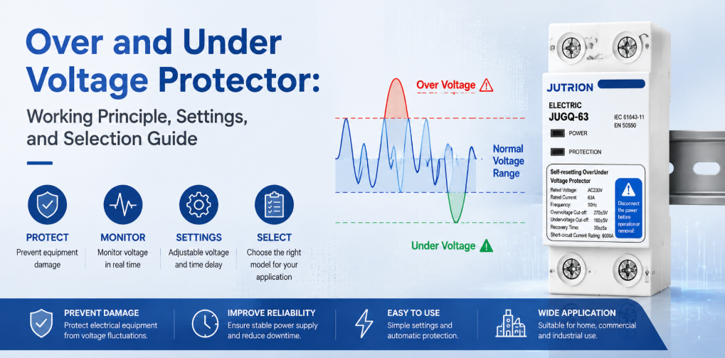
Nguyên lý hoạt động và hướng dẫn lựa chọn bộ bảo vệ quá áp và thấp ápTrả lời nhanh: Bộ bảo vệ quá áp và thấp áp có chức năng gì?
Bộ bảo vệ quá áp và thấp áp ngắt mạch khi điện áp nguồn duy trì trên hoặc dưới giới hạn đã chọn, sau đó đóng lại sau khi điện áp phục hồi và thời gian trễ cài đặt trước kết thúc. Thiết bị bảo vệ chống quá áp kéo dài, thấp áp và sụt áp. Thiết bị không thay thế SPD cho quá áp xung, cầu dao cho quá dòng, RCD cho dòng rò đất, hoặc AVR khi cần hiệu chỉnh điện áp liên tục.
“Bảo vệ điện áp” thường được xem là một chủ đề duy nhất, nhưng tủ phân phối có thể gặp nhiều sự kiện khác nhau về bản chất. Quá áp xung do sét có thể kéo dài micro giây. Sự cố điều chỉnh lưới điện hoặc máy biến áp đấu nối sai đầu phân áp có thể giữ nguồn trên mức bình thường trong nhiều phút. Đường dây quá tải có thể gây sụt áp kéo dài. Dây trung tính lỏng hoặc hở có thể đẩy một số tải một pha trong hệ thống ba pha bốn dây lên cao hơn nhiều so với điện áp danh định trong khi khiến các tải khác thấp hơn.
Không có thiết bị đơn lẻ nào xử lý tất cả các điều kiện này. Thiết bị chống sét lan truyền giới hạn quá áp xung ngắn, năng lượng cao. Bộ bảo vệ quá áp và thấp áp ngắt tải khi điện áp RMS nguồn nằm ngoài giới hạn cho phép. Cầu dao ngắt dòng quá tải và ngắn mạch. RCD hoặc RCBO phản ứng với dòng dư. Do đó, quy tắc lựa chọn đầu tiên không phải là định mức dòng điện hay loại màn hình: mà là khớp thiết bị với loại nhiễu loạn.
Đối với nhà chế tạo tủ điện hoặc nhà phân phối, câu hỏi hữu ích không phải là liệu “bảo vệ điện áp” có hiện diện hay không. Câu hỏi hữu ích là liệu mỗi nhiễu loạn có phương pháp cảm biến, phản ứng đóng cắt và quy tắc phục hồi được xác định rõ ràng hay không.
Ranh giới bảo vệ: Khớp từng vấn đề điện áp với đúng thiết bị
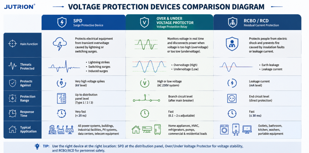
Sơ đồ so sánh thiết bị bảo vệ điện áp cho thấy chức năng SPD, bộ bảo vệ quá áp thấp áp và RCBO RCD| Nhiễu loạn | Thời gian điển hình | Phản ứng chính | Thiết bị chịu trách nhiệm thông thường |
|---|---|---|---|
| Sét hoặc xung đóng cắt | Từ micro giây đến mili giây | Kẹp và triệt tiêu năng lượng quá độ | Thiết bị bảo vệ xung (SPD) |
| Quá điện áp duy trì | Giây, phút hoặc lâu hơn | Ngắt tải bị ảnh hưởng | Bộ bảo vệ quá điện áp hoặc rơ le giám sát điện áp |
| Thiếu điện áp hoặc sụt áp | Giây, phút hoặc lâu hơn | Ngắt trước khi thiết bị quá nhiệt, ngừng hoạt động hoặc trục trặc | Bộ bảo vệ thiếu điện áp hoặc rơ le giám sát điện áp |
| Quá tải hoặc ngắn mạch | Phụ thuộc vào mức độ sự cố | Ngắt dòng điện quá mức | MCB hoặc MCCB |
| Rò điện đất | Từ mili giây đến duy trì | Phát hiện dòng dư và ngắt | RCCB hoặc RCBO |
| Dao động điện áp cần hiệu chỉnh liên tục | Liên tục hoặc lặp lại | Tăng, giảm hoặc ổn định điện áp | Bộ ổn áp hoặc AVR |
Một tủ điện được thiết kế tốt có thể chứa nhiều thiết bị trong số này vì chúng hoạt động trên các thang thời gian khác nhau và quan sát các đại lượng điện khác nhau. Việc lắp đặt SPD không làm cho bảo vệ quá điện áp duy trì trở nên không cần thiết. Việc bổ sung bộ bảo vệ điện áp không làm tăng khả năng cắt của một cầu dao nhỏ. Phối hợp đúng là cộng hưởng, không phải cạnh tranh.
Tại sao cầu dao có thể không ngắt khi điện áp xấu
Cầu dao thông thường phản ứng chủ yếu với dòng điện. Nếu điện áp nguồn tăng nhưng thiết bị được kết nối không ngay lập tức tiêu thụ đủ dòng điện để vượt qua đường cong thời gian-dòng điện của cầu dao, cầu dao có thể vẫn đóng trong khi các thiết bị điện tử nhạy cảm chịu ứng suất điện gây hại. Trong thời gian thiếu điện áp, động cơ có thể tiêu thụ nhiều dòng điện hơn để tạo ra mô-men xoắn cần thiết, nhưng phản ứng chính xác phụ thuộc vào động cơ, tải và bộ điều khiển. Cầu dao cuối cùng có thể ngắt, nhưng nó không được thiết kế để giám sát xem điện áp nguồn có chấp nhận được hay không.
Bộ bảo vệ điện áp khắc phục điểm mù này bằng cách đo điện áp trực tiếp. Khi bảo vệ quá dòng cũng được tích hợp vào bộ bảo vệ, chức năng đó vẫn nên được phối hợp với thiết bị bảo vệ ngắn mạch phía trước. MCB hoặc MCCB phía trước vẫn rất cần thiết để ngắt sự cố an toàn.
Vị trí của bộ bảo vệ quá và thiếu điện áp
Bộ bảo vệ quá và thiếu điện áp là thiết bị giám sát và đóng cắt được sử dụng giữa nguồn điện và tải hoặc mạch phân phối phía sau. Mạch cảm biến của nó lấy mẫu điện áp đầu vào. Bộ điều khiển so sánh giá trị đo được với các ngưỡng trên và dưới đã cấu hình. Nếu điện áp nằm ngoài cửa sổ cho phép trong thời gian phản ứng áp dụng, thiết bị sẽ mở các tiếp điểm đóng cắt hoặc ra lệnh cho một công tắc tơ bên ngoài mở.
Các mẫu tự động đóng lại tiếp tục giám sát nguồn trong khi tải bị ngắt. Khi điện áp trở lại trong giới hạn phục hồi, bộ điều khiển bắt đầu thời gian trễ kết nối lại. Tải chỉ được khôi phục nếu nguồn vẫn chấp nhận được trong suốt thời gian trễ đó. Điều này ngăn chặn chu kỳ bật-tắt nhanh và cho máy nén, hệ thống làm lạnh, bộ nguồn điện tử và các thiết bị khác thời gian ổn định trước khi khởi động lại.
Các tên gọi phổ biến bao gồm bộ bảo vệ quá/thiếu điện áp, thiết bị bảo vệ điện áp, bộ chuyển mạch điện áp tự động, bộ bảo vệ điện áp tự phục hồi, bộ bảo vệ tự động đóng lại và rơ le giám sát điện áp. Các thuật ngữ này chồng chéo nhau, nhưng chúng không phải lúc nào cũng mô tả các sản phẩm giống hệt nhau. Một số thiết bị đóng cắt tải trực tiếp. Một số khác cung cấp tiếp điểm rơ le cho một Contactor AC. Một số chỉ giám sát điện áp; một số khác bổ sung đo dòng điện, bảo vệ quá dòng, giám sát mất pha hoặc màn hình kỹ thuật số.
Quá điện áp duy trì và thiếu điện áp gây ra điều gì cho thiết bị
Quá điện áp duy trì
Quá áp kéo dài làm tăng ứng suất điện môi và có thể đẩy nhanh quá trình lão hóa cách điện. Tụ điện nguồn, MOV, trình điều khiển LED, biến áp điều khiển và đầu vào bán dẫn có thể hoạt động gần hoặc vượt quá giới hạn thiết kế. Công suất gia nhiệt điện trở tăng xấp xỉ theo bình phương điện áp khi điện trở không đổi, vì vậy ngay cả mức tăng điện áp vừa phải cũng có thể tạo ra mức tăng nhiệt lớn hơn. Hậu quả có thể là hỏng hóc ngay lập tức, ngừng hoạt động gây phiền toái hoặc tuổi thọ bị rút ngắn khó liên hệ với sự kiện nguồn ban đầu.
Các nguyên nhân có thể bao gồm đầu nối biến áp sai, lỗi bộ điều chỉnh, lỗi đấu dây, sự cố AVR máy phát, loại bỏ tải, lỗi trung tính và nguồn cấp không phù hợp với thiết bị được kết nối. Bộ bảo vệ điện áp không thể khắc phục nguyên nhân, nhưng có thể cách ly tải trong khi tình trạng đó còn tồn tại.
Điện áp thấp và sụt áp lưới
Điện áp thấp không chỉ đơn giản là “ít công suất hơn.” Động cơ có thể không tăng tốc được hoặc có thể bị ngừng trệ khi có tải. Công tắc tơ có thể rung lập bập hoặc nhả ra. Rơ le và bộ điều khiển có thể đặt lại một cách khó lường. Tải điện tử công suất không đổi có thể cố gắng kéo thêm dòng điện khi điện áp giảm, làm tăng ứng suất nhiệt lên dây dẫn và linh kiện. Máy nén làm lạnh đặc biệt nhạy cảm với việc khởi động lại nhiều lần trước khi áp suất cân bằng.
Phản ứng đúng phụ thuộc vào tải. Một số thiết bị điện tử có dải đầu vào rộng và có thể vượt qua mức sụt áp vừa phải. Bơm dẫn động bằng động cơ có thể cần ngắt nhanh. Hệ thống điều khiển quan trọng có thể cần UPS thay vì chỉ ngắt đơn giản. Do đó, ngưỡng và độ trễ của bộ bảo vệ phải được chọn từ yêu cầu của thiết bị, không được sao chép mù quáng từ tủ điện khác.
Mất trung tính: Mối nguy hiểm nghiêm trọng trong hệ thống ba pha bốn dây
Trong hệ thống ba pha bốn dây cân bằng, các tải pha-trung tính tương tự nhau và dòng trung tính có thể tương đối thấp. Các hệ thống lắp đặt thực tế hiếm khi cân bằng hoàn hảo. Nếu dây trung tính bị lỏng hoặc đứt ở phía trước các tải một pha không bằng nhau, điểm trung tính có thể bị dịch chuyển. Khi đó, điện áp pha-trung tính được xác định bởi trở kháng tải thay vì giữ cố định ở giá trị danh định.
Một nhóm tải có thể chịu quá áp nghiêm trọng trong khi nhóm khác chịu điện áp thấp, mặc dù điện áp pha-pha vẫn có vẻ bình thường. Điều này khiến sự kiện mất trung tính đặc biệt nguy hiểm trong các tủ điện hỗn hợp thương mại, dân dụng, viễn thông và công nghiệp nhẹ. Hư hỏng thiết bị có thể xảy ra trước khi thiết bị quá dòng thông thường phát hiện được sự cố đủ lớn để cắt.
Cụm giám sát điện áp ba pha nên đánh giá mọi pha liên quan và, khi ứng dụng yêu cầu, cả điện áp pha-trung tính. Mất pha, mất cân bằng pha và tính toàn vẹn của trung tính cần được xem xét một cách rõ ràng. Một phép đo đơn lẻ trên một pha không thể thay thế cho việc giám sát đầy đủ tải ba pha bốn dây.
Lưu ý thiết kế: bộ bảo vệ điện áp làm giảm mức tiếp xúc của thiết bị; nó không làm cho trung tính bị lỗi trở nên an toàn. Các đầu nối lỏng, dây dẫn có tiết diện quá nhỏ, ăn mòn và sự cố mạng phía trước phải được tìm ra và khắc phục.
Bảo vệ một pha và ba pha là những quyết định khác nhau
Bộ bảo vệ một pha thường đưa ra một quyết định trung tâm: điện áp pha-trung tính đo được có nằm trong cửa sổ vận hành cho phép hay không? Điều đó nghe có vẻ đơn giản, nhưng khi lắp đặt vẫn phải xác định điện áp danh định, dòng điện mà thiết bị mang, cần đóng cắt một hay hai dây dẫn, và cách xử lý dây trung tính theo hệ thống nối đất tại địa phương. Một sản phẩm được ghi cho mạch danh định 230 V không thể chỉ chọn dựa trên mức dòng 63 A được ghi trên nhãn.
Các ứng dụng một pha thường bao gồm căn hộ, cửa hàng nhỏ, tủ viễn thông, mạch điện lạnh, bảng chiếu sáng và từng máy riêng lẻ. Tải của chúng có thể phản ứng rất khác nhau trước cùng một sự kiện. Một bộ điều khiển LED có thể chịu được sụt áp ngắn khiến cuộn dây contactor nhả. Một tủ lạnh có thể sống sót qua sụt áp nhưng lại bị hỏng nếu khởi động lại ngay lập tức. Do đó, một bộ bảo vệ được chọn tốt sẽ kết hợp cửa sổ điện áp chính xác với độ trễ phục hồi phù hợp với tải nhạy cảm nhất với việc khởi động lại ở phía hạ lưu.
Những gì bộ bảo vệ ba pha có thể cần quan sát
Bảo vệ ba pha không chỉ đơn thuần là ba bản sao của phép đo một pha. Chức năng giám sát có thể cần đánh giá điện áp pha-pha, điện áp pha-trung tính, mất pha, thứ tự pha và mất cân bằng điện áp. Chức năng nào quan trọng phụ thuộc vào tải và cách bố trí dây dẫn. Một đường cấp động cơ ba dây có hồ sơ rủi ro khác với một bảng phân phối bốn dây cấp cho hàng chục mạch một pha không đều nhau.
- Mất pha nghĩa là một pha nguồn bị mất hoặc đã sụp đổ. Một động cơ ba pha đang chạy có thể tiếp tục hoạt động với dòng điện quá mức ở các pha còn lại, mô-men giảm và nóng lên nhanh chóng. Một thiết bị bảo vệ dành cho nhiệm vụ liên quan đến động cơ nên phát hiện tình trạng này hoặc làm việc với một rơ-le bảo vệ động cơ có chức năng đó.
- Thứ tự pha xác định chiều quay của nhiều động cơ ba pha. Thông thường nó quan trọng khi vận hành thử hoặc sau khi thay đổi đấu nối nguồn. Chức năng quá áp và thấp áp không tự động bao hàm bảo vệ thứ tự pha, vì vậy tính năng cần thiết phải được nêu rõ.
- Mất cân bằng điện áp mô tả điện áp các pha không bằng nhau. Một mất cân bằng điện áp tưởng chừng khiêm tốn có thể tạo ra mất cân bằng dòng điện lớn hơn nhiều trong động cơ. Giới hạn chấp nhận được nên đến từ thiết kế động cơ và hệ thống. Một thiết bị chỉ ngắt ở ngưỡng quá áp và thấp áp rộng có thể không cung cấp giám sát mất cân bằng chuyên dụng.
- Dịch chuyển điểm trung tính là trọng tâm khi tải pha-trung tính không bằng nhau. Nếu một thiết bị ba pha chỉ đo các giá trị pha-pha, nó có thể không thấy sự phân tách pha-trung tính gây hại do trung tính bị hở. Người chế tạo tủ điện nên xác nhận chính xác thiết bị được chọn cảm nhận những điện áp nào thay vì dựa vào cụm từ “ba pha” trong danh mục.
| Hệ thống và tải | Các phép đo cần ưu tiên | Phương pháp đóng cắt điển hình |
|---|---|---|
| Phân phối cuối cùng một pha 230 V | Quá áp và thấp áp pha-trung tính | Đóng cắt trực tiếp khi định mức và phối hợp cho phép |
| Đường cấp động cơ ba pha 400 V | Điện áp pha-pha, mất pha, mất cân bằng và có thể cả thứ tự pha | Thiết bị giám sát điều khiển công tắc tơ định mức động cơ |
| Tủ điện tải hỗn hợp bốn dây 400/230 V | Tất cả các điện áp pha-trung tính liên quan, mất pha và dịch chuyển liên quan đến trung tính | Cách ly nhiều cực được chọn theo sơ đồ nối đất |
| Phân phối có máy phát dự phòng | Điện áp trên nguồn đang hoạt động cộng với tần số và trạng thái hệ thống chuyển nguồn khi cần | Phối hợp với bộ điều khiển máy phát và thiết bị chuyển nguồn |
Sự phân biệt này cũng ảnh hưởng đến so sánh sản phẩm. Một thiết bị bảo vệ tự phục hồi một pha nhỏ gọn có thể là thiết bị tuyệt vời cho tủ điện tiêu dùng nhưng lại là kiến trúc điều khiển sai cho tủ điện động cơ ba pha lớn. Ngược lại, một cụm rơ-le giám sát pha và công tắc tơ phức tạp có thể thêm chi phí và không gian tủ mà một mạch một pha tiêu chuẩn hóa không cần. Lựa chọn đúng là kiến trúc nhỏ nhất giám sát mọi tình trạng điện áp có khả năng gây hại cho tải thực tế.
Cách hoạt động của thiết bị bảo vệ điện áp tự đóng lại
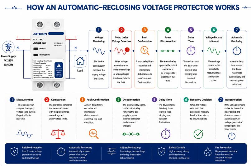
Sơ đồ nguyên lý hoạt động của thiết bị bảo vệ điện áp tự đóng lại- Đo lường: mạch cảm biến lấy mẫu điện áp nguồn và, trên các mẫu áp dụng được, dòng điện hoặc các tình trạng pha bổ sung.
- So sánh: bộ điều khiển so sánh các giá trị đo được với các giới hạn quá áp và thấp áp đã lập trình.
- Xác nhận sự cố: lọc hoặc trễ ngắt loại bỏ nhiễu không đáng kể và các nhiễu loạn rất ngắn không nên ngắt tải.
- Ngắt kết nối: các tiếp điểm bên trong mở ra, hoặc một rơ-le đầu ra ngắt nguồn cuộn dây khỏi công tắc tơ bên ngoài.
- Tiếp tục giám sát: nguồn vẫn được theo dõi trong khi tải phía hạ lưu được cách ly.
- Quyết định phục hồi: khi điện áp trở về dải phục hồi chấp nhận được, một bộ định thời bắt đầu.
- Đóng lại: nếu nguồn duy trì ổn định trong toàn bộ thời gian trễ, thiết bị tự động đóng lại. Nếu điện áp lại trở nên không chấp nhận được, bộ định thời đặt lại.
Lấy mẫu kỹ thuật số dựa trên bộ vi xử lý giúp các ngưỡng điều chỉnh, thời gian trễ, màn hình hiển thị và logic trạng thái trở nên thực tế trong một thiết bị DIN-rail nhỏ gọn. Việc lọc nhiễu rất quan trọng trong các hệ thống lắp đặt có nhiều nhiễu điện vì các chuyến cắt nhầm có thể gây gián đoạn gần như chính sự kiện điện áp. Bộ lọc và thời gian xác nhận nên loại bỏ các sai lệch không đáng kể mà không che giấu tình trạng kéo dài có thể làm hỏng tải.
Tại sao Mức Cắt, Mức Phục Hồi và Độ Trễ Phải Phối Hợp Với Nhau
Một bộ bảo vệ không đưa ra một quyết định điện áp. Nó thường đưa ra ít nhất ba quyết định liên quan: khi nào nguồn cấp trở nên không chấp nhận được, khi nào nó đã phục hồi đủ để được coi là chấp nhận được trở lại, và nó phải duy trì ổn định trong bao lâu trước khi tải được kết nối lại. Các giá trị này tạo thành một chiến lược điều khiển và nên được xem xét cùng nhau.
Nếu mức cắt và mức phục hồi quá gần nhau, nguồn cấp dao động quanh ranh giới có thể gây ra việc đóng mở lặp đi lặp lại. Một giá trị phục hồi riêng biệt tạo ra độ trễ: ví dụ, sau khi cắt do điện áp thấp, điện áp phải tăng lên mức khỏe mạnh hơn trước khi có thể kết nối lại. Bộ định thời kết nối lại sau đó xác nhận rằng sự phục hồi là ổn định chứ không phải chỉ là tạm thời.
Thời gian chính xác phụ thuộc vào tải. Một bộ gia nhiệt điện trở có thể chấp nhận việc quay trở lại tương đối nhanh. Một máy nén lạnh có thể cần thời gian tạm dừng lâu hơn trước khi khởi động lại. Một tủ điện có nhiều động cơ có thể cần kết nối lại theo từng giai đoạn để dòng khởi động kết hợp của chúng không kéo nguồn cấp xuống dưới ngưỡng một lần nữa. Đây là lý do tại sao độ trễ điều chỉnh được là một thông số kỹ thuật, chứ không chỉ đơn thuần là một tính năng tiện lợi.
Đối với mẫu có thể điều chỉnh, hãy ghi lại các giá trị cắt, phục hồi và độ trễ đã được phê duyệt thành một bộ cài đặt. Việc chỉ thay đổi ngưỡng cao hoặc thấp có thể làm thay đổi độ trễ dự kiến và hành vi khởi động lại. Đối với mẫu được hiệu chuẩn tại nhà máy, hãy xác nhận rằng cửa sổ điều khiển đặt trước phù hợp với nguồn cấp đích và thiết bị được kết nối trước khi chuẩn hóa nó trong toàn bộ dự án.
Cách Chọn Bộ Bảo Vệ Quá Áp và Thấp Áp
Xác Nhận Điện Áp Hệ Thống, Tần Số và Cách Bố Trí Pha
Bắt đầu với hệ thống phân phối thực tế, không phải tiêu đề trong catalogue. Ghi lại điện áp pha-trung tính và pha-pha danh định, tần số, cách bố trí một pha hoặc ba pha, số lượng dây dẫn, việc sử dụng dây trung tính và dung sai nguồn cấp chấp nhận được. IEC 60038 cung cấp các tham chiếu điện áp tiêu chuẩn, bao gồm các hệ thống hạ áp 230/400 V phổ biến, nhưng đặc tả kỹ thuật của dự án và các quy tắc cung cấp điện địa phương quyết định các yêu cầu cuối cùng.
Đối với tải ba pha, xác định xem thiết bị có cần giám sát thêm mất pha, thứ tự pha, mất cân bằng và dịch chuyển pha-trung tính hay không. Đối với tủ điện chứa nhiều tải một pha, việc giám sát liên quan đến dây trung tính có thể quan trọng hơn so với tải động cơ ba dây cân bằng.
2. Define the Load That Will Be Disconnected
List the connected load, maximum demand, continuous current, inrush current and load type. A 40 A resistive circuit, a 40 A motor feeder and a 40 A bank of switched-mode power supplies do not impose identical switching duty. Identify compressors, pumps, transformers, capacitive inputs and equipment with internal undervoltage or restart controls.
Do not select solely from the service breaker rating. The protector must be suitable for the current it carries and the switching duty it performs, while the upstream protective device must provide the required short-circuit protection. Terminal capacity, conductor size, ambient temperature and enclosure ventilation also matter.
3. Decide Between Direct Switching and an External Contactor
A compact protector can switch a suitably rated load directly when its contact rating, utilization duty and prospective fault coordination are appropriate. For a larger panel, a motor-heavy load, frequent operation or a current beyond the protector’s direct-switching capability, use a monitoring relay or protector to control a correctly selected contactor. This separates the measurement logic from the power switching duty.
When an external contactor is used, check coil voltage, contactor utilization category, auxiliary contacts, control-circuit protection and fail-safe behavior. Decide what happens after a power loss and whether automatic restart is permitted by the process risk assessment.
4. Set the Overvoltage and Undervoltage Limits
The trip window should be wide enough to tolerate normal supply variation and narrow enough to protect the connected equipment. Use the most restrictive credible requirement from the equipment manufacturer, project specification and local installation rules. A value seen in a generic example is not automatically suitable for motors, refrigeration, medical equipment, telecom power supplies or process controls.
| Setting | Purpose | Selection question |
|---|---|---|
| Overvoltage trip level | Defines the high-voltage disconnection point | What sustained input can the most sensitive connected equipment tolerate? |
| Undervoltage trip level | Defines the low-voltage disconnection point | At what voltage can motors, contactors or power supplies no longer operate safely? |
| Trip delay | Rejects brief deviations | Which short disturbances can the load ride through without harm? |
| Recovery level | Defines when voltage is acceptable again | Is sufficient hysteresis provided to avoid repeated switching? |
| Thời gian trễ đóng lại | Waits for stable supply and safe restart | Does the load need seconds or minutes before restart? |
5. Select Reconnection Delay for the Load
A short delay can restore lighting or non-critical resistive loads quickly. Refrigeration and air-conditioning compressors often require a longer delay to allow pressure equalization and avoid a hard restart. Multiple loads reconnecting simultaneously can create a new voltage dip, so large installations may require staged restarting rather than one common timer.
Automatic reconnection is convenient, but it is not appropriate everywhere. Machinery that could move unexpectedly may require manual reset, a safety controller or another supervised restart sequence. Voltage restoration must never bypass machine-safety requirements.
6. Check Poles, Neutral Arrangement and Isolation
Select the number of poles from the system earthing arrangement and installation requirements. Switching the neutral is not a universal rule. In some systems it is required; in others it may be prohibited or unnecessary. The choice must be coordinated with upstream bonding, source transfer arrangements and local codes. Never treat a two-pole or four-pole catalogue option as proof that it is correct for every network.
7. Verify Coordination and Installation Conditions
Confirm rated current, operational voltage, frequency, terminal capacity, mounting method, temperature range, enclosure protection and the required upstream protective device. Check short-circuit coordination rather than assuming a small modular device can interrupt any available fault current. Verify conductor torque and provide working space and ventilation according to the manufacturer’s instructions.
IEC 60364-4-44 addresses protection of low-voltage installations against voltage disturbances and electromagnetic disturbances. Apply the edition and national adoption required by the destination market; do not use an IEC reference as a substitute for a complete project design.
Standards and Export-Market Questions That Change the Specification
Standards references should define the engineering boundary, not decorate a product description. IEC 60364-4-44:2024 addresses protection of low-voltage installations against voltage disturbances and electromagnetic disturbances. It is an installation-level document: it helps designers consider the consequences of disturbances within an electrical installation, but it is not a model datasheet and does not by itself prove that a particular protector is suitable for a project.
IEC 60038 defines standard voltage values used as references for equipment and supply systems. Nominal voltage is the starting point for a protector setting, not the complete setting decision. Normal service variation, the connected equipment’s permissible input range, regional supply-quality requirements and the behavior of the recovery logic all affect the usable window.
Product Standard, Installation Code and Supply Quality
These three layers answer different questions. A product standard describes how a device is classified, constructed and tested. An installation code determines how equipment is selected and erected in a building or plant. A supply-quality document describes characteristics expected at the point of supply. A buyer should not substitute one layer for another. For example, knowing that a country uses a 230/400 V nominal system does not determine the required neutral switching, and an installation-code reference does not establish the short-circuit capability of an individual product.
The destination market may also use a national adoption of an IEC document with local modifications. North American projects use different system conventions, product listings and installation rules. The familiar functions—measure, compare, disconnect and delay reconnection—remain understandable, but product acceptance, conductor switching, enclosure marking and coordination have to be checked in the regional framework.
Certification Claims Must Match the Exact Model
Terms such as IEC, UL and CB should be supported by documentation that identifies the relevant standard, model or series, electrical ratings and issuing body. A general factory capability statement is not the same as a certificate covering every variant. Importers and panel builders should match the document reference to the ordered catalogue number and destination-market requirement.
The same discipline applies to rated current and protection claims. If a series includes several current or pole variants, evidence for one variant should not automatically be extended to all others. Where a protector includes overcurrent functionality, clarify its operating characteristic and its relationship to the upstream breaker. “Overcurrent” on a display does not automatically mean the device provides the short-circuit interruption performance expected from an MCB or MCCB.
A Compact Export Specification
Before comparing models, put the project conditions on one line: destination market; nominal voltage and frequency; phase and neutral arrangement; continuous current and load type; overvoltage and undervoltage limits; trip and reconnection timing; number of switched poles; direct switching or contactor control; upstream protection; mounting and environmental conditions; and required conformity documents. That line exposes mismatches quickly and prevents three products with the same front-panel current marking from being treated as equivalent.
For distributors serving several countries, adjustable models can reduce stock fragmentation, but only when setting control is managed. A setting range is useful if commissioning personnel know the approved values and unauthorized changes are prevented. For one stable market and a repeatable panel design, factory-calibrated thresholds may produce more consistent installation and simpler training. The export decision is therefore partly electrical and partly operational.
Choosing Between the Three JUTRION Series
JUTRION offers three over and under voltage protector series for different panel and procurement priorities. Product selection should still be confirmed against the required electrical ratings and project documentation.
| Selection point | JRGQ-63 | JQGQ-63 | JUGQ-63 |
|---|---|---|---|
| Series position | Flagship adjustable model | Compact digital model | Cost-effective preset model |
| Display and monitoring | Dual digital display with real-time voltage and current monitoring | Compact digital display with smart monitoring | Simplified interface for plug-and-play use |
| Voltage settings | Adjustable overvoltage and undervoltage parameters | Adjustable thresholds | Factory-calibrated thresholds |
| Additional function stated on the public page | Overcurrent protection and automatic reclosing | Automatic reclosing | Automatic reclosing |
| Định dạng lắp đặt | 35 mm DIN-rail modular format | Space-saving DIN-rail format | Streamlined DIN-rail format |
| Best fit | Projects needing visible operating data and broad parameter control | High-density distribution boards where space matters | Standardized, high-volume applications requiring simple installation |
| Confirm from the ordered model datasheet | Rated voltage, current, poles, exact setting and delay ranges, terminals, temperature limits, dimensions, switching duty, upstream protection and model-specific conformity documents | ||
Choose JRGQ-63 when adjustment, current information and a more complete on-device interface are valuable. Choose JQGQ-63 when adjustable digital protection is needed but panel density is the main constraint. Choose JUGQ-63 when the required protection window matches the factory-calibrated configuration and consistency, simplicity and volume economics are more important than field adjustment.
A buyer should not compare only unit price. Normalize rated voltage, current, poles, adjustable range, trip and recovery logic, delay range, switching method, display, overcurrent function, terminals, certifications, packaging and customization. Two devices described as “63 A automatic voltage protectors” can offer materially different functions.
Apply the Selection Logic to Four Panel Scenarios
Commercial Distribution Board on an Unstable Grid
A small commercial facility experiences long evening brownouts and occasional high voltage during light-load periods. The panel supplies lighting, point-of-sale equipment, refrigeration and office electronics. A voltage protector can disconnect selected downstream circuits outside the approved window. Because refrigeration has a different restart requirement from lighting and office loads, the designer may divide the loads or use separate control so one common reconnection delay does not compromise either continuity or compressor protection.
OEM Panel for Pumps or HVAC Equipment
The load includes motors with high starting current and a control circuit sensitive to low voltage. Direct switching through a compact protector may not be the preferred architecture. The protector can monitor the source and command an AC contactor selected for the motor duty. The control design should prevent unsafe automatic restart and coordinate undervoltage behavior with the motor protection relay and process controller.
Three-Phase Panel with Many Single-Phase Loads
A 400/230 V panel distributes different single-phase circuits across the three phases. Unequal loading makes an open neutral hazardous. The monitoring strategy should observe all relevant phase-to-neutral voltages and disconnect the affected distribution section if values diverge beyond permitted limits. Maintenance procedures must still locate and repair the neutral fault.
High-Volume Standardized Consumer Unit
An OEM produces many panels for one market with a stable, predefined protection specification. Field adjustment is not needed and could create commissioning inconsistency. A factory-calibrated automatic-reclosing model such as JUGQ-63 may provide a simpler fit, provided its nominal voltage, current, thresholds, poles and certification match the project.
Install, Commission, and Diagnose the Protection System
Installation and Commissioning Checklist
- Confirm the source is isolated and follow the project’s lockout procedure.
- Verify nominal voltage, frequency, phase arrangement and conductor identification.
- Confirm whether the protector switches the load directly or controls a contactor.
- Check upstream short-circuit and overload protection.
- Match conductor size and terminal capacity; tighten to the specified torque.
- Program thresholds and delays from the approved setting schedule.
- Test overvoltage and undervoltage operation with suitable test equipment rather than by creating unsafe supply conditions.
- Verify the trip indication, contact state and reconnection timer.
- Confirm that motors and machinery restart safely.
- Record settings, model, serial or batch information and commissioning results.
After commissioning, investigate frequent trips instead of simply widening thresholds. Repeated operation may reveal a loose neutral, undersized feeder, overloaded transformer, generator-control issue or supply-quality problem. The protector is often the messenger, not the cause.
Common Selection and Installation Mistakes
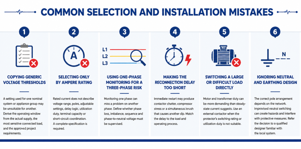
Common selection and installation mistakes of automatic re-closing voltage protector- Copying generic voltage thresholds: A setting used for one nominal system or appliance group may be unsuitable for another. Derive the operating window from the actual supply, the most sensitive connected load, and the approved project requirements.
- Selecting only by ampere rating: Rated current does not describe voltage range, poles, adjustable settings, delay logic, utilization duty, terminal capacity or short-circuit coordination. A complete specification is required.
- Using one-phase monitoring for a three-phase risk: Monitoring one phase can miss a problem on another phase. Define whether phase loss, imbalance, sequence and phase-to-neutral voltage must be supervised.
- Making the reconnection delay too short: Immediate restart may produce contactor chatter, compressor stress or a simultaneous inrush that causes another dip. Match the delay to the load and operating process.
- Switching a large or difficult load directly: Motor and transformer duty can be more demanding than steady-state current suggests. Use an external contactor when the protector’s switching rating or utilization duty is not suitable.
- Ignoring neutral and earthing design: The correct pole arrangement depends on the network. Improvised neutral switching can create hazards and interfere with protective measures. Refer the decision to a qualified designer familiar with the local system.
Maintenance and Troubleshooting in Service
A voltage protector normally requires little routine intervention, but it should still be included in the panel inspection plan. Check for discoloration, heat damage, loose terminals, dust accumulation, cracked housings and abnormal display values. Compare the displayed voltage with a calibrated instrument when readings appear doubtful. Thermal imaging under representative load can help reveal a poor terminal connection, although it does not replace torque checks performed under safe isolated conditions.
Keep a record of trip events where operational continuity matters. The time, displayed voltage, affected phase, connected load and recovery time can distinguish a supply-quality issue from a load-related voltage drop. Several trips at the same production time may indicate feeder demand. Random high and low readings across single-phase circuits may point toward a neutral problem. Trips only during generator operation may indicate AVR settings, frequency variation or poor generator/load matching.
| Observed symptom | Possible causes to investigate | Useful checks |
|---|---|---|
| Trips immediately after installation | Wrong nominal-voltage model, wiring error, threshold set too close to normal supply | Verify model, line/neutral connections, measured voltage and setting schedule |
| Repeated trip and reconnect cycle | Insufficient hysteresis, unstable supply, restart inrush causing another dip | Record voltage during restart; review recovery level and delay |
| Display is on but load remains off | Active fault, delay still counting, damaged contact, external contactor/control issue | Read status indication and test control circuit according to the manual |
| One phase shows abnormal voltage | Loose phase or neutral, phase imbalance, upstream connection fault | Isolate safely and inspect all conductors; measure every relevant phase |
| Terminal temperature is high | Loose termination, unsuitable conductor, overload, poor enclosure ventilation | Measure load current, inspect conductor preparation and verify specified torque |
Do not repeatedly reset or bypass a protector until the cause is known. Bypassing removes the protection at the moment the system may be demonstrating a genuine fault. If the device has switched a severe or repeated load, inspect its contacts and connected conductors according to the manufacturer’s service instructions. Replace a unit that shows heat damage, unreliable switching or readings outside its declared accuracy rather than attempting an unapproved repair.
Settings should also be controlled. For adjustable models, record the approved values during commissioning and restrict unauthorized changes. If equipment is added, the supply changes, or the panel is exported to a market with a different nominal voltage, review the entire setting schedule. A protector that was correctly configured for the original installation may be inappropriate after a system modification.
Câu hỏi Thường gặp
Why does the protector wait before reconnecting the load?
The delay confirms that voltage has recovered and prevents rapid cycling. It can also provide restart time for compressors and reduce the chance that simultaneous inrush drives the supply low again.
Can it protect against a lost neutral?
It can reduce exposure if it monitors the affected phase-to-neutral voltages and disconnects when they leave the permitted range. It cannot repair the neutral fault, and the monitoring arrangement must cover all relevant phases.
Is an over/under voltage protector the same as a voltage stabilizer?
No. A protector disconnects the load. A stabilizer or AVR attempts to correct the output voltage while continuing to supply it. Choose according to whether shutdown or continuous regulated power is required.
How do I choose the ampere rating?
Determine the maximum current the device will carry, consider load duty and inrush, select a suitable rating with the required terminals and installation conditions, and coordinate it with upstream fault protection. Use an external contactor when direct switching is unsuitable.
What reconnection delay should I use?
Use the connected equipment manufacturer’s requirement and the process risk assessment. General lighting may accept a short delay; compressors and staged systems may need substantially longer or sequenced reconnection.
Why does the protector keep tripping?
Possible causes include genuine supply variation, a loose neutral, overloaded feeder, generator regulation problems, incorrect settings, wiring errors or a device/load mismatch. Measure and diagnose the system before widening the thresholds.
Choose the Protection Boundary Before the Product Variant
An over and under voltage protector is most effective when its operating window is defined precisely. Selection becomes a practical sequence: establish the nominal system and monitored conductors, understand the load, choose direct switching or contactor control, set coordinated trip and recovery values, choose a safe reconnection delay, verify poles and neutral design, and test the completed panel under controlled conditions.
For a model recommendation, send JUTRION the nominal voltage and frequency, phase and neutral arrangement, load current and type, required thresholds and delay, pole configuration, upstream protective device, installation conditions, certification market and order quantity. The JRGQ-63, JQGQ-63 and JUGQ-63 ranges can then be compared against the actual project instead of selected from current rating alone.
