

Trả lời nhanh: Bạn cần hộp gom điện mặt trời cỡ nào?
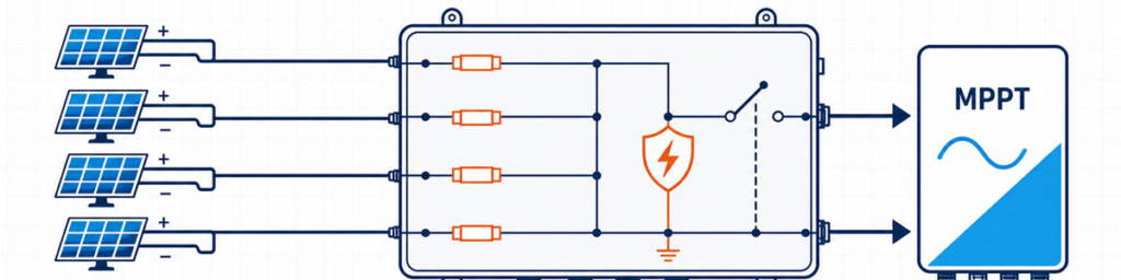
Bốn chuỗi PV kết nối qua hộp gom điện mặt trời có cầu chì đến một đầu vào MPPT của biến tầnA solar combiner box should match the number of compatible PV strings feeding one inverter input, the array’s highest cold-weather open-circuit voltage, the combined Isc-based design current, and the protection required at that location. Input count alone is not enough. Four strings may need one 4-in/1-out box, two separate 2-in/1-out circuits, or no external combiner at all, depending on the inverter and cable layout.
For a buyer, “4 strings, 1000 V” sounds like a usable specification. For the engineer checking the quotation, it is only the beginning. The module datasheet may show that the string approaches 1000 V on a cold morning. The inverter may assign the strings to two independent MPPTs. The output path may need to carry nearly 70 A after the project’s current factor is applied. Any one of those facts can change the box.
Mục tiêu ở đây là biến thông tin đã có sẵn trên bảng dữ liệu tấm pin, bảng biến tần và sơ đồ một sợi thành một đặc tả sơ bộ có thể bảo vệ được. Đối với các cấu hình chung và tùy chọn sản phẩm có sẵn, xem dòng hộp gom PV JUTRION.
Bắt đầu từ bản vẽ biến tần, không phải từ số chuỗi trên mái
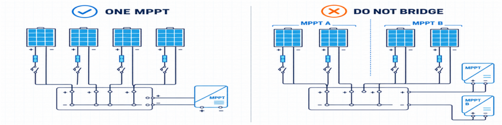
Phân nhóm chuỗi PV đúng cho một MPPT so với việc nối cầu sai các đầu vào MPPT riêng biệtCác chuỗi đi vào một đầu ra của hộp gom phải có nơi đến hợp lệ. Điều đó nghe hiển nhiên, nhưng đây lại là chỗ nhiều báo giá ban đầu sai.
Giả sử một mái có tám chuỗi. Bản vẽ biến tần phân bốn chuỗi cho MPPT A và bốn chuỗi cho MPPT B. Yêu cầu một hộp gom 8 vào/1 ra sẽ nối hai mạch mà biến tần được thiết kế để điều khiển độc lập. Các lựa chọn khả thi thường là hai nhóm 4 vào/1 ra riêng biệt, một vỏ hộp chứa hai phần độc lập về điện, hoặc đấu chuỗi trực tiếp nếu biến tần đã cung cấp đầu vào và bảo vệ phù hợp.
Các chuỗi dự định vận hành song song cũng phải thực sự tương thích. Kiểm tra loại tấm pin, số tấm mỗi chuỗi, hướng và bóng che dự kiến. Các chuỗi có độ dài không bằng nhau có điện áp vận hành khác nhau. Việc gộp chuỗi bị che nhiều và chuỗi không bị che cũng có thể tạo ra sự phối hợp vận hành kém ngay cả khi nhãn tấm pin giống hệt nhau.
Điều này cho quy tắc khả dụng đầu tiên:
Đếm số chuỗi được phân cho một đường MPPT tương thích, không phải mọi chuỗi nhìn thấy trên bản vẽ dự án.
Khi hộp gom ngoài ít mang lại giá trị
Nhiều biến tần chuỗi đã cung cấp sẵn nhiều đầu vào DC, chống sét lan truyền bên trong và chức năng cách ly DC. Nếu mỗi chuỗi có thể đi thẳng đến một đầu vào biến tần phù hợp, việc thêm hộp gom ngoài có thể tạo thêm các điểm đấu cáp mà không giải quyết được vấn đề thiết kế nào.
Hộp một chuỗi là trường hợp liên quan nhưng khác. Bộ 1 vào/1 ra không gom dòng; nó hoạt động như một hộp bảo vệ và cách ly bên ngoài. Điều đó có thể hữu ích khi biến tần ở xa, cần một điểm cách ly cục bộ, hoặc dự án muốn có chống sét lan truyền thay thế được ở vị trí dễ tiếp cận.
Năm con số đáng đưa lên một tờ
Trước khi xem cỡ cầu chì hay kích thước vỏ hộp, hãy thu thập năm nhóm thông tin. Hầu hết có thể sao chép trực tiếp từ các tài liệu dự án đã phát hành.
| Thông tin | Nơi thường lấy | Điều nó làm thay đổi |
|---|---|---|
| Voc, Isc, Imp, hệ số nhiệt độ và cầu chì nối tiếp tối đa | Bảng dữ liệu tấm pin PV | Giới hạn điện áp, dòng điện và cầu chì chuỗi |
| Số module mỗi chuỗi và số chuỗi song song | Sơ đồ chuỗi | Số lượng đầu vào và tổng điện áp/dòng điện |
| Bố trí MPPT và giới hạn đầu vào | Bảng dữ liệu biến tần và sơ đồ một sợi | Những chuỗi nào có thể dùng chung một đầu ra |
| Nhiệt độ tối thiểu, cách lắp đặt và mức phơi nhiễm | Cơ sở thiết kế dự án và dữ liệu địa điểm | Voc lạnh, hệ số giảm định mức và vỏ hộp |
| Quốc gia đích và quy định áp dụng | Đặc tả kỹ thuật dự án | Phương pháp bảo vệ và tài liệu |
One value that often gets missed is the inverter’s maximum permissible short-circuit current. The maximum operating current and maximum short-circuit current are not interchangeable. A proposed array should be checked against both.
Quốc gia đích quan trọng không kém dữ liệu điện. Một phép tính cầu chì chuẩn bị cho dự án theo tiêu chuẩn IEC không nên âm thầm mượn hệ số nhân của Bắc Mỹ rồi trình bày như một quy tắc phổ quát.
Kiểm tra điện áp chuỗi lạnh trước khi chọn 1000 V hay 1500 V
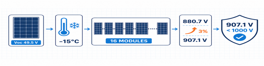
Tính toán Voc chuỗi PV thời tiết lạnh cho 16 module cho ra điện áp thiết kế 907,1 VVoc của module thường được nêu ở điều kiện thử nghiệm tiêu chuẩn. Giá trị này tăng khi nhiệt độ tế bào giảm, vì vậy điều kiện lạnh nhất dự kiến sẽ quyết định điện áp chuỗi tối đa.
Khi bảng dữ liệu module đưa ra hệ số nhiệt độ Voc âm theo phần trăm trên mỗi độ C, phép tính ban đầu là:
Voc,lạnh = Voc,STC × [1 + |βVoc| × (25 − Tmin)]
Vchuỗi,lạnh = Voc,lạnh × number of modules in series
Enter the coefficient as a decimal. For example, −0.28%/°C becomes 0.0028 in the formula. If the module manufacturer provides a different low-temperature method, use that method instead.
The answer has to fit more than the inverter. The fuse-link and holder, SPD, switch-disconnector or breaker, terminals, conductors and completed assembly all sit in the same DC circuit. Replacing only the SPD with a 1500 V device does not convert a 1000 V box into a 1500 V assembly.
A little unused voltage margin is not wasted capacity. It absorbs the project-specific temperature basis and tolerances that have actually been identified. What should be avoided is a random margin with no recorded source.
String Fuses Depend on Reverse Current, Not on Habit
When parallel strings are healthy, each contributes current to the common output. If one string develops a fault, the others may feed current back into it. The string fuse is there to interrupt that damaging reverse current where protection is required.
An initial screen for the contribution from the other strings is:
Ireverse,screen = (n − 1) × Isc,string
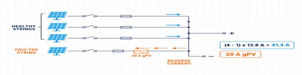
Reverse current from three healthy PV strings into a faulted string protected by a 20 A gPV fuseHere, n is the number of parallel strings. The expression shows why the answer changes quickly between two and four inputs: a faulted string in a four-string group may receive current from three healthy strings.
Do not treat that expression as the finished protection design. The selected gPV fuse must carry expected current under the actual enclosure conditions, protect the cable and equipment, stay within the module’s maximum series-fuse rating, and have adequate PV DC voltage and breaking capability. The holder and fuse are checked together, including temperature and grouping effects.
IEC 60269-6 covers supplementary requirements for fuse-links used in photovoltaic strings and arrays up to 1500 V DC. The installation rules adopted for the project determine how that product is applied.
About the 1.56 × Isc Figure Seen Online
The familiar 1.56 × Isc figure is associated with two 125% factors used in common North American design paths. It should not be relabelled as a universal IEC formula. If the project is governed by the NEC, use the adopted edition, equipment listings and local requirements. If it is an IEC project, apply the relevant IEC-based installation rules and the module, fuse and cable manufacturers’ instructions.
This distinction is worth stating in the quotation. Otherwise, two suppliers may return different fuse sizes even though both received the same array data.
Size the Combined Path Separately from Each Input
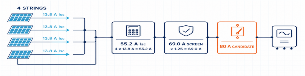
Four 13.8 A PV strings combined to 55.2 A Isc with a 69 A design screen and 80 A output-device candidateThe input and output sides carry different currents. Each input carries one string; the common output carries the sum of the parallel strings.
Isc,total = number of parallel strings × Isc,string
The project’s required design factor and correction factors are then applied to the appropriate conductors and equipment. The result affects internal wiring, busbars, terminals, the outgoing cable and the output switching device. It also needs to be compared with the inverter’s stated limits.
Using Imp alone for the entire selection can leave the protection path too small. Using Isc alone without checking the inverter’s normal MPPT current can miss an operating limitation. Keep the values separate and give each one a purpose.
| Value | Use it to check |
|---|---|
| String Imp | Normal operating current and inverter MPPT compatibility |
| String Isc | String design current and overcurrent-protection calculations |
| Total Isc | Combined path and inverter short-circuit-current limit |
| Corrected project design current | Conductors, busbars, terminals and output device under installed conditions |
Heat can overrule an apparently comfortable catalogue rating. Closely grouped fuse-holders, terminal losses, the SPD and direct solar radiation all add to enclosure temperature. An 80 A device in a reference condition is not automatically an 80 A solution inside every outdoor box.
Fuses, Isolation, Breakers and SPDs Have Different Jobs
A combiner box is easier to specify when every component has one clear duty:
- gPV fuse: protects an individual string against the applicable reverse-overcurrent condition;
- switch-disconnector: provides PV DC-rated load switching and a defined isolation point;
- DC circuit breaker: switches the circuit and provides an overcurrent function when its characteristics and DC interruption ratings suit the application;
- PV DC SPD: limits transient overvoltage and does not replace overcurrent protection or isolation.
An output breaker is not mandatory simply because there is room for one. The system design may call for a switch-disconnector where overcurrent protection is already provided elsewhere, or for a breaker with a defined protective duty. Decide the function first.
The same principle applies to the SPD. Confirm the PV DC application, UCPV, protection modes, protection level, discharge-current duty, short-circuit behaviour and backup coordination. Type 2 is commonly used for induced surge conditions. Where an external lightning protection system or another lightning-current path is present, the arrangement may need Type 1 or Type 1+2 protection. See the JUTRION PV DC SPD range after the project voltage and lightning context are known.
For the isolating function, a device rated for the intended PV duty is more meaningful than a generic “DC switch” description. The JUTRION PV DC isolator range includes DC-PV2 options for review against the required voltage, current and pole arrangement.
A Four-String Example from Datasheet to Box
Illustrative example: This is a constructed commercial-rooftop case used to show the calculation. It is not a customer project or a universal design.
Four identical strings are assigned to one high-current inverter input. Each string contains 16 modules. The module datasheet gives Voc = 49.5 V, Isc = 13.8 A, βVoc = −0.28%/°C and a maximum series-fuse rating of 25 A. The project minimum temperature is −15°C. Its design basis also applies a stated 3% allowance after the temperature calculation.
The illustrative inverter has a 1000 V maximum DC input, an 80 A maximum input current and a 100 A maximum short-circuit current. No external lightning protection system is assumed.
The Drawing Points to Four Inputs and One Output
All four strings use the same modules and string length, and the inverter documentation permits them to feed the same input. A 4-in/1-out architecture is therefore appropriate at this stage. If the drawing divided them between two MPPTs, the answer would become two independent 2-in/1-out groups.
The Cold String Reaches 907.1 V
Cold module Voc = 49.5 × [1 + 0.0028 × (25 − (−15))] = 55.04 V
Cold string Voc = 55.04 × 16 = 880.7 V
Project design voltage = 880.7 × 1.03 = 907.1 V
A verified 1000 V assembly can pass this preliminary check, as can the illustrative inverter. The remaining margin is about 93 V. A seventeenth module would raise the result to approximately 964 V before the same allowance and would not pass this example after the allowance is applied.
Parallel Strings Make Individual Fusing Necessary
The other three strings can contribute an initial reverse-current screen of:
(4 − 1) × 13.8 = 41.4 A
That is above the module’s 25 A maximum series-fuse rating, so individual string protection is required in this example. The project method produces a preliminary lower fuse-current screen of 1.25 × 13.8 = 17.25 A. A 20 A gPV fuse sits between that value and the 25 A module limit. Before it is accepted, its holder, cable protection, enclosure temperature and continuous-current capability must be checked.
The Common Output Needs More Than a 55.2 A Label
The combined short-circuit current is:
4 × 13.8 = 55.2 A
The example design basis uses 1.25 × Isc as its preliminary output-current screen:
1.25 × 55.2 = 69.0 A
An 80 A PV DC switch-disconnector is a reasonable starting frame, not an automatic final choice. The installed thermal rating, voltage, poles and switching duty remain to be checked. The inverter’s 100 A short-circuit limit passes the 55.2 A comparison. Its 80 A operating limit should be compared with four times the module Imp from the real datasheet.
The preliminary box is now specific enough to review: four independently fused inputs, one combined output, 1000 V-class components throughout, a combined path designed around the stated 69 A screen, PV DC isolation and a Type 2 PV DC SPD subject to final coordination.
The Result on One Page
The calculation is easier to review when the assumptions, result and remaining check are kept together. This is also the point where a buyer can see whether two quotations are actually based on the same duty.
| Selection item | Illustrative result | What still needs confirmation |
|---|---|---|
| Configuration | 4 inputs / 1 output | All four strings feed one compatible inverter input |
| Maximum project voltage | 907.1 V | Site temperature basis, tolerance method and inverter limit |
| String protection | 20 A gPV preliminary selection | Fuse-holder temperature, cable protection and applicable rules |
| Combined short-circuit current | 55.2 A | Inverter maximum permissible short-circuit current |
| Preliminary output-current screen | 69.0 A | Correction factors and installed assembly temperature |
| Output isolation | 80 A frame is a starting candidate | PV DC duty, voltage, poles and installed current rating |
| Surge protection | Type 2 PV DC SPD initially | Ucpv, protection modes, LPS and backup coordination |
| Enclosure | Outdoor IP65 minimum | UV, corrosion, heat, glands and condensation |
Choosing Between a 1/1, 2/1 and 4/1 Configuration
JUTRION currently displays 1000 V DC, IP65 products in 1-in/1-out, 2-in/1-out and 4-in/1-out configurations. Use the input count to shortlist the architecture, then confirm the ratings that the project calculation produced.
| Configuration | Typical reason to shortlist it | Reason to stop and reconsider |
|---|---|---|
| 1 input / 1 output | One string needs an accessible protection and isolation point | No combining occurs; verify that a separate box adds a required function |
| 2 inputs / 1 output | Two matched strings feed one inverter input | The strings belong to separate MPPTs or exceed the combined-input limits |
| 4 inputs / 1 output | Four matched strings feed one suitably rated high-current input | The inverter needs two MPPT groups or the output path is underrated |
The worked example points toward a JUPV1000-4/1 architecture. It does not approve the internal fuse, output device or SPD by model name alone. Those parts have to be quoted against the 907.1 V project voltage, the proposed 20 A gPV string protection, the 69 A preliminary combined-current screen and the outdoor installation conditions.
Custom 1500 V or larger-string configurations deserve a fresh component and assembly check. They should not be treated as a label change to the 1000 V stock arrangement.
The Outdoor Enclosure Can Change the Current Rating
Electrical calculations are often completed in an office at 25°C. The box may spend its working life on a roof where the air is much hotter, direct sunlight warms the enclosure, and several fuse-holders carry current side by side. That difference affects more than comfort during maintenance.
Heat is produced at fuses, terminals, conductors, the SPD and the output device. Closely packed components have less opportunity to cool, while a sealed enclosure restricts air exchange. A component that carries its marked current under its reference conditions may require derating in the final assembly. This is why the 80 A switch-disconnector in the example remains a starting frame until the installed arrangement has been checked.
IP65 is useful, but it answers only an ingress-protection question. It does not automatically establish:
- resistance to long-term ultraviolet exposure;
- corrosion performance near the coast or in an industrial atmosphere;
- acceptable internal temperature under full current and solar loading;
- condensation control during daily heating and cooling;
- suitability of cable glands, seals and materials for the installed cables;
- insulation performance at high altitude.
Mounting details also matter. Cable entries made through the top of an outdoor enclosure create a different water path from bottom entry. Undersized glands may damage seals or leave insufficient cable support. Tight cable bends can transfer mechanical force to fuse-holders and terminals. The enclosure should be reviewed as an installed assembly, not as an empty plastic or metal box with an IP number.
IEC 61439-2:2020 covers power switchgear and controlgear assemblies up to 1500 V DC. The relevance here is practical: using individually rated components does not remove the need to verify the completed assembly, including temperature rise, dielectric properties, protective circuits, clearances, wiring and mechanical construction as applicable.
Send Enough Information for the Supplier to Check the Result
A short technical enquiry is more useful than a long purchasing template. Attach the module and inverter datasheets and state:
- strings per output and modules per string;
- module Voc, Isc, Imp, βVoc and maximum series fuse;
- minimum design temperature and any voltage allowance;
- inverter MPPT arrangement and input limits;
- calculated maximum voltage and combined design current;
- required fuse, isolation, breaker and SPD functions;
- enclosure location, IP requirement, ambient, UV and corrosion exposure;
- cable sizes, monitoring, destination market and quantity.
For the illustrative project, that becomes: 4-in/1-out, four identical 16-module strings feeding one MPPT, 907.1 V stated project design voltage, preliminary 20 A gPV fuses, 55.2 A total Isc, 69 A preliminary output-current screen, PV DC isolation, coordinated Type 2 PV DC surge protection and an outdoor enclosure.
Why Two “4-String, 1000 V, IP65” Quotations May Not Be Equivalent
One quotation may use gPV fuse-links and holders verified for the intended voltage and temperature. Another may list only a nominal fuse current. One box may provide a load-break switch-disconnector; another may use a device intended mainly for isolation. SPD Ucpv, protection modes, short-circuit behaviour and replaceability may also differ even when both quotations say “Type 2 SPD.”
The common output is another source of hidden difference. Compare the installed current capability of the busbars, conductors, terminals and output device, not only the largest ampere number printed in the bill of materials. Also check terminal capacity against the actual outgoing cable. A technically lower-priced quotation is not cheaper if it requires replacement glands, a larger enclosure or rework at site.
A useful comparison therefore normalizes the following items before price:
- input/output arrangement and MPPT grouping;
- maximum DC voltage of the complete path;
- string-fuse class, rating and module limit;
- combined current and installed temperature conditions;
- output device function and DC duty;
- SPD type, Ucpv, modes and coordination;
- terminal and cable-gland capacity;
- enclosure material and environmental suitability.
The final selection should read as one connected electrical path. If the quotation confirms only input count, nominal voltage and IP rating, it has not yet answered the sizing question.
Verify the Box After Installation
A correct design can still be compromised by reversed polarity, loose terminations, damaged glands or a string connected to the wrong input. Commissioning should follow the project procedure and component instructions, with the DC circuit isolated and tested by qualified personnel.
Before energizing the combined output, record:
- string identity, polarity and measured open-circuit voltage;
- whether measured string voltages are reasonably consistent with the design and with one another;
- terminal tightening completed to the specified torque;
- protective-conductor and bonding continuity where required;
- fuse type and rating in every populated way;
- SPD status indication and remote alarm contact, if fitted;
- operation and position indication of the isolating device;
- labels, unused-entry seals, gland compression and enclosure closure.
After the system has operated under representative load, inspect for abnormal heating, discoloration, odour, nuisance fuse operation or moisture. Where the project maintenance plan uses thermography, the baseline image is more useful when load and ambient conditions are recorded with it. The purpose is not to “prove” the design from one scan, but to leave a reference for later comparison.
IEC 62548-1:2023 provides the broader IEC design context for PV arrays, including DC wiring, protection, switching and earthing. The completed assembly also needs appropriate verification; IEC 61439-2:2020 covers power switchgear and controlgear assemblies up to 1500 V DC. PV DC SPD requirements are addressed by IEC 61643-31.
To compare the result with a JUTRION configuration, send the string schedule, module and inverter data, site temperature, protection requirements and destination standard through the PV combiner box page. That gives both sides something more reliable to discuss than “four strings, best price.”
Câu hỏi Thường gặp
How Many Solar Strings Require a Combiner Box?
There is no universal minimum. An external combiner is useful when compatible strings need to be paralleled before one inverter input, when it reduces long cable runs, or when the project needs a centralized location for fuses, isolation, surge protection or monitoring. If an inverter already accepts every string directly and provides the required functions, a separate combiner may not be necessary.
What Size Fuse Should Be Used in a Solar Combiner Box?
Select a PV-rated gPV fuse from the string Isc, applicable installation method, cable capacity, environmental conditions and module maximum series-fuse rating. The fuse must carry expected current without nuisance operation while remaining low enough to protect the module and cable. Do not apply 1.56 × Isc as a universal IEC rule; the calculation depends on the destination standard.
Can Strings Connected to Different MPPTs Share One Combiner Box?
They may share a physical enclosure only if the MPPT circuits remain electrically separate. Do not combine the outputs of independent MPPT groups unless the inverter manufacturer explicitly permits that architecture. Each group should have its own compatible strings, output path and ratings.
Do I Need a 1000V or 1500V PV Combiner Box?
Calculate the maximum cold-weather open-circuit voltage of the complete string and include the allowances required by the project method. Select a voltage class that keeps the inverter and every component in the combiner path within rating. A 1500 V SPD alone does not make the completed box suitable for 1500 V.
What Is the Difference Between a PV Combiner Box and a PV Protection Box?
A PV combiner box joins two or more compatible string inputs into a common output. A 1-in/1-out PV protection box does not combine strings; it provides a convenient location for functions such as isolation, surge protection or overcurrent protection on one string circuit.
