

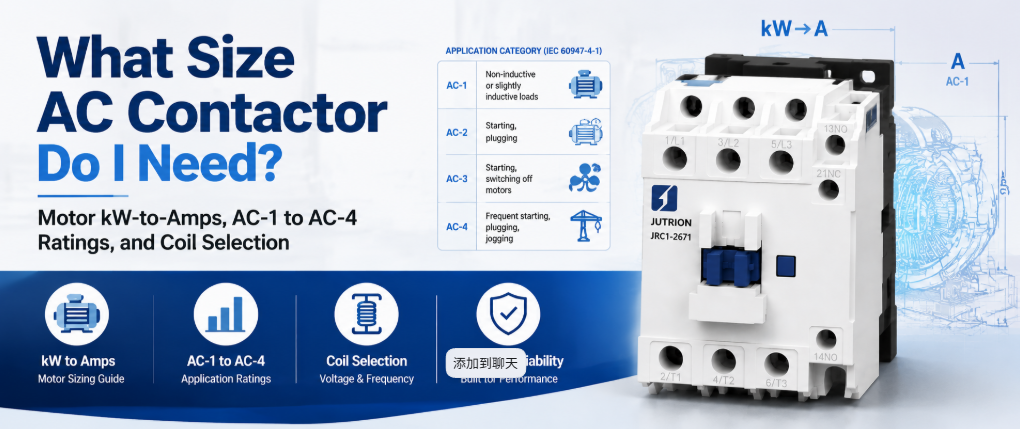
クイックアンサー:ACコンタクタの役割とは?
ACコンタクタは、コイル駆動の電磁石を使用して指令に応じて電力回路を開閉する電気制御スイッチであり、接点が溶着したり摩耗したりすることなく、数千回から数百万回の開閉ができるように作られています。指示されたときに負荷電流を開閉します。回路を保護するものではありません。正しいサイジングとは、ラベルに印刷されている最大の数値ではなく、実際の負荷動作に適用される定格に合わせてサイジングすることを意味します。.
20Aと表示されたコンタクタは、モーターにとっては20Aのデバイスではありません。同じ物理的ユニットが、抵抗ヒーターでは20A、かご形モーターでは9Aと定格されることがあります。これは、モーターの突入電流と誘導性の遮断が、ヒーターよりもはるかに接点に負担をかけるためです。この単一の区別が、他のどの選定ミスよりも多くの早期コンタクタ故障を引き起こしています。.
このガイドでは、コンタクタが負担しなければならないもの、その計算方法、適用される使用カテゴリ、そしてアンペア数値に続く極数、コイル、補助接点、寿命、協調のチェックについて説明します。.
開閉の仕事に適したデバイスを選ぶ
何かをサイジングする前に、コンタクタがその仕事に適したデバイスであることを確認してください。パネル設計では、1つの部品に無関係な2つの機能を期待することで失敗することがよくあります。.
| 機器 | 主な役割 | 開閉頻度 | 故障時のトリップ |
|---|---|---|---|
| ACコンタクタ | 指令に応じて負荷電流を開閉する | 頻繁なサイクル用に設計されている | なし。別途過負荷リレーまたはブレーカーが必要 |
| 汎用リレー | 低電力の開閉と信号制御 | より軽い動作向けに定格されている | なし |
| MCBまたはMCCB | 過電流および短絡保護 | 通常のサイクルではなく、時折の操作 | あり |
| モータースターター | コンタクタと過負荷リレーを1つにまとめたもの | コンタクタと同じ | あり、過負荷リレーを介して |
| ソフトスターターまたはVFD | モーター電流の制御されたランプ | オン/オフではなく連続制御 | モデルによって異なる |
指令に応じて負荷を繰り返しオン/オフする方法が問題なら、答えはコンタクタです。回路を過負荷から保護するものが問題なら、それは別のデバイスです。コンタクタが両方を行うかのように扱うのは、最も一般的なパネル設計のミスの1つです。.
リレーやブレーカーが代わりにならない理由
汎用リレーは回路を閉じることはできますが、モーターやヒーターの電流レベルで長期間にわたってそれを行うようには作られていません。コンタクタは機械的寿命が数百万回の動作と定格されているのに対し、汎用リレーは実際の電気負荷の下ではそのごく一部の定格しかありません。その違いは接点材料、ばね力、アーク抑制にあります。コンタクタは接点形状と、大型フレームではアークシュートを使用して、接点が孔食や溶着を起こすことなく誘導性モーター電流を繰り返し遮断します。そのような動作に使われたリレーは、通常負荷の下で接点が溶着して閉じたまま故障します。これはコンタクタの徐々の摩耗よりもはるかに悪い故障モードです。.
回路ブレーカーは回路を保護するために設計されており、通常の自動化ロジックの一部としてサイクルさせるためではなく、時折操作するためのものです。ブレーカーを負荷開閉スイッチとして使用すると、その保護寿命が短くなり、定格された用途ではありません。コンタクタと保護デバイスは2つの異なる仕事をし、同じ回路に一緒に属します。.
ACコンタクタの仕組み
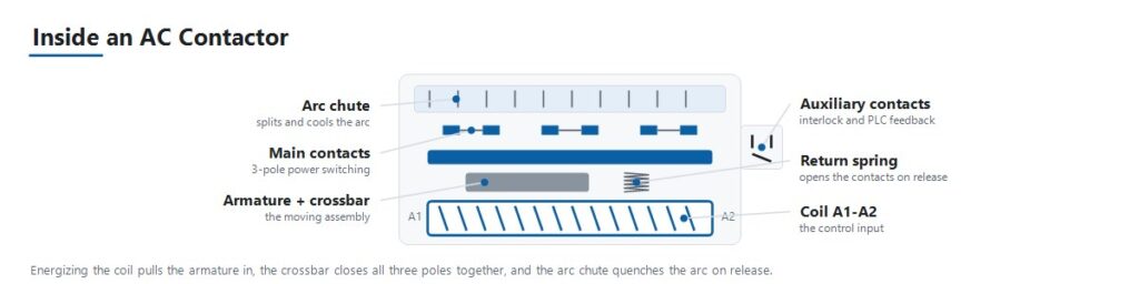
動作シーケンスは、このガイドで後述する故障モードのほとんどを説明しています。.
- 制御信号がコイルを通電します。. PLC出力、サーモスタット、押しボタンロジックなどの制御回路が、定格コイル電圧でコイルに電圧を印加します。.
- 電磁石が可動子を引き込みます。. 通電されたコイルが磁界を発生させ、可動子を固定コアに向かって引き寄せます。.
- 主接点が閉じます。. 可動子の動きにより、共通クロスバーを介して主電源接点が閉じ、負荷が電源に接続されます。.
- 補助接点が状態を切り替えます。. 同じ可動子に連動する小型の補助接点が、主接点と同期して開閉します。これらはインターロック、表示、およびコンタクタが実際に閉じたことのPLCへの確認を提供します。.
- ばね力が接点圧力を保持します。. 振動や負荷がかかっても安定した接点圧力が維持されることで、接点バウンスや接点面での抵抗発熱が防止されます。.
- コイルを消勢すると回路が開きます。. 制御信号がなくなると磁界が消滅し、戻りばねが可動子を引き戻して主接点が開きます。.
- Arc suppression handles the interruption. Opening a circuit under load, especially an inductive motor load, draws an arc across the separating contacts. Contact geometry and arc chutes extinguish that arc quickly enough to prevent damage on every cycle.
Utilization Categories Decide the Real Current Rating
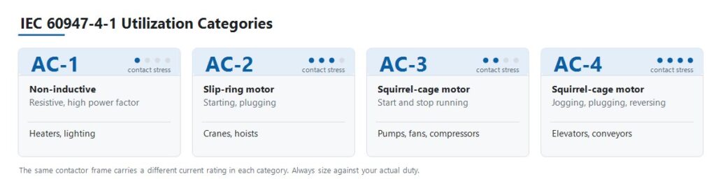
IEC 60947-4-1 defines utilization categories that describe how hard a load is on the contacts, not simply how many amperes it draws. This is the step most selection errors trace back to.
| Category | Load type | Switching duty | Typical application |
|---|---|---|---|
| AC-1 | Non-inductive or slightly inductive, high power factor | No significant inrush | Resistive heaters, HVAC heating banks, general lighting |
| AC-2 | Slip-ring (wound-rotor) motors | Starting and plugging under load | Cranes, hoists |
| AC-3 | Squirrel-cage motors | Starting, and switching off a running motor | Pumps, fans, compressors |
| AC-4 | Squirrel-cage motors | Jogging, plugging, rapid reversing | Elevators, conveyors, machine tools |
The consequence is that a single contactor carries several different current ratings. A JUTRION JRC1-D09 is rated 20 A in category AC-1 and 9 A in category AC-3. Both figures describe the same physical device. Sizing a pump against the 20 A number puts the contactor at more than twice its motor-duty rating, and the contacts will show it.
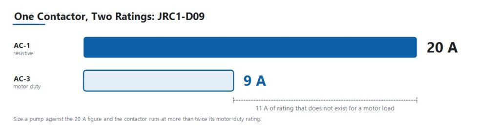
Read every published rating together with the category it belongs to. A frame is not a crane model or a jogging model. It is one frame with several ratings, and the duty decides which rating applies to the project.
Convert the Motor Data into Amps
Use a verified full-load current directly when the project already provides one. When the data is given as motor power, convert it using the correct voltage and phase arrangement.
Three-Phase Motors
I = P × 1,000 / (√3 × VLL × cos φ × η)
Single-Phase Loads
I = P × 1,000 / (V × cos φ × η)
Here, I is line current in amperes, P is motor rated output power in kW, VLL is three-phase line-to-line voltage, V is single-phase voltage, cos φ is power factor, and η is efficiency.
Power factor for standard induction motors typically falls between 0.80 and 0.88, and efficiency between 0.85 and 0.93 depending on efficiency class. Use the nameplate values whenever they are available. The typical ranges are for preliminary work before the motor datasheet arrives.
For purely resistive single-phase loads such as heating elements, power factor and efficiency are effectively unity, and the expression reduces to I = P × 1,000 / V.
The JUTRION AC contactor sizing calculator performs the same calculation and returns a minimum AC-3 operational current. It is a starting point for the specification, not a substitute for the motor nameplate or the manufacturer’s rating tables.
Apply the Load-Type Multipliers and Ambient Derating
Certain loads draw far more than their steady-state current at the moment of switching. Long-standing industry practice applies a multiplier to account for that behaviour. These conventions are not values defined in IEC 60947-4-1, so treat them as a first pass and confirm them against actual inrush data for critical or large circuits.
| Load type | Conventional multiplier | Reason |
|---|---|---|
| Capacitor banks | Approximately 1.5 × capacitor rated current | Capacitive inrush at switch-on is severe and very short |
| Transformers and welding sets | Approximately 2 × rated current | Magnetizing inrush can reach many times steady-state current |
| Gas-discharge and HID lighting | Approximately 1.1 to 1.4 × rated current | Ballast inrush and warm-up behaviour |
| Poor cooling or densely packed enclosure | 110 to 120 percent of load rated current | Elevated internal temperature reduces current capacity |
| Continuously running motor, long duty | Contactor rated current reduced by approximately 30 percent | Sustained thermal loading of the contacts |
Ambient Temperature and Enclosure Conditions
A contactor’s rated current assumes the reference ambient temperature stated on its datasheet. Above that temperature, current-carrying capacity falls, but the derating slope is specific to the manufacturer and the frame. Use the derating curve from the actual product documentation rather than a generic percentage.
Two conditions apply regardless of product. First, base the calculation on the temperature inside the enclosure, not the room. A densely packed panel in a warm plant runs considerably hotter than ambient. Second, contactors mounted side by side with no spacing heat one another, so respect the manufacturer’s minimum spacing or derate further.
A Worked Example: 4 kW Pump Motor at 400 V
A three-phase centrifugal pump motor in an OEM water-treatment panel. Standard start and stop duty, approximately 20 starts per hour, panel ambient around 35 °C.
Step 1. Establish the utilization category. A squirrel-cage induction motor, started and stopped normally, is category AC-3. It is not AC-1, even though the load is described as a simple pump.
Step 2. Calculate full-load current. Nameplate values are 4 kW, 400 V, cos φ = 0.85, η = 0.90.
I = 4 × 1,000 / (1.732 × 400 × 0.85 × 0.90)
Working the denominator: 1.732 × 400 = 692.8, then × 0.85 = 588.9, then × 0.90 = 530.0.
I = 4,000 / 530.0 ≈ 7.6 A
Step 3. Select against the AC-3 rating. The requirement is a contactor whose AC-3 rating covers 7.6 A with margin. The JRC1-D09 is rated 9 A at AC-3, giving approximately 18 percent headroom over the calculated full-load current. Note what was not done: the same JRC1-D09 carries a 20 A AC-1 rating, and sizing this pump against that figure would have been the single most common contactor selection error.
Step 4. Check ambient and duty. At 35 °C panel ambient with 18 percent headroom, verify the figure against the product’s derating curve before committing. That margin is comfortable in a well-ventilated panel and tighter in a densely packed one. At 20 starts per hour, confirm that the rated operations per hour and the AC-3 electrical life comfortably exceed the expected duty across the panel’s service life.
Step 5. Specify coil voltage. The panel’s control transformer secondary is 220 V AC, so the coil is specified at 220 V. It is not 400 V, even though the motor runs at 400 V.
Step 6. Add protection. Pair the contactor with a correctly sized overload relay set to the motor’s full-load current, and confirm Type 1 or Type 2 coordination with the upstream breaker or fuse. A normal start under 10 seconds points to a Class 10 trip class here. The overload relay setting calculator converts nameplate current, service factor, and start duration into a preliminary setting and trip class.
Result: a JRC1-D09, three-pole, with a 220 V AC coil, plus an overload relay. The selection was derived from the load, not from a catalogue.
The same procedure applies at higher power. An 18.5 kW motor at 400 V works out to roughly 35 A full-load current and requires a contactor with an AC-3 rating above that figure.
Use This Seven-Step AC Contactor Selection Process
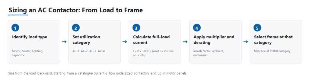
Step 1: Identify the Load Type and Utilization Category
Establish whether the load is resistive, a standard squirrel-cage motor, a wound-rotor motor starting under load, or a motor subject to jogging and reversing. Everything downstream depends on this answer, because it determines which of the contactor’s several current ratings actually applies.
Step 2: Calculate Operational Current and Confirm Voltage
Use the formulas above to obtain full-load current, apply the relevant load-type multiplier, then confirm that the contactor’s rated operational current Ie at your utilization category covers it with margin. Match the rated operational voltage Ue to the system line voltage.
Step 3: Select Coil Voltage
Coil voltage is a separate specification from load voltage. A 380 V motor circuit may be switched by a 24 V DC or 220 V AC coil depending on the control architecture. Confirm what the control circuit actually supplies, whether that is a PLC output, a control transformer secondary, or a DC control supply, before ordering.
Step 4: Choose Pole Count and Configuration
Three-pole is standard for three-phase motor loads. Four-pole is used where neutral switching or an additional independent circuit is required. Confirm the arrangement against the system earthing design, since neutral switching is required in some systems and unnecessary or prohibited in others.
Step 5: Specify Auxiliary Contacts
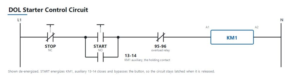
Determine how many normally open and normally closed auxiliary contacts are needed for interlocking, PLC status feedback, and indicator lamps, and whether they are integral or added as a separate auxiliary block. In a standard direct-on-line starter, an auxiliary contact wired in parallel with the start button is what latches the control circuit so the contactor stays energized after the operator releases the button. Auxiliary contacts are inexpensive to specify at design stage and awkward to retrofit afterwards.
Step 6: Check Electrical Life Against Actual Duty Cycle
For frequently cycling applications such as jogging, reversing, or high-frequency automation sequences, check the rated operations per hour and the electrical life at your utilization category. Mechanical life, measured without load, is always the higher and less relevant figure.
Step 7: Coordinate with Upstream Protection
Pair the contactor with a correctly sized overload relay for motor loads, then coordinate with an upstream breaker or fuse sized for short-circuit protection. On larger distribution boards that upstream device is often an air circuit breaker. Contactor selection is one link in a chain that runs from load current, to breaker rating, to prospective fault current, to device breaking duty. Getting the contactor right while leaving that chain unverified simply relocates the problem.
IEC 60947-4-1 and NEMA Ratings Are Not Interchangeable Labels
AC contactors sold internationally are generally built to IEC 60947-4-1, which defines the utilization categories and the rating structure used throughout this guide. The current fifth edition was published in 2023 and supersedes the 2018 edition. It is worth checking which edition a project specification references, because they are not identical.
North American markets commonly reference NEMA ICS 2 contactor ratings instead of, or alongside, IEC utilization categories. The two systems classify contactors differently, since NEMA uses size classes rather than AC-1 through AC-4. A specification written for one market does not translate automatically to the other. When sourcing for a North American project, confirm which framework the buyer’s specification actually requires before quoting a part.
Treat the product standard, the installation code, and any market-specific requirement as three separate questions. Confirming one does not answer the others.
Type 1 and Type 2 Coordination
Short-circuit coordination under IEC 60947-4-1 determines how much damage a fault causes to the contactor and starter. Type 1 permits damage to the equipment after a short-circuit fault, provided the damage is contained and no hazard results, and the equipment may require repair or replacement. Type 2 requires that the equipment remains suitable for further use, with only light contact welding permitted. These are different commercial and engineering outcomes. Confirm which one the project specification requires before selecting the combination.
Choosing Between the JUTRION JRC1 Ratings
JUTRION manufactures the JRC1 series AC contactor on its own production lines in Wenzhou, Zhejiang, built to IEC 60947-4-1. Coil voltage options include 24 V, 48 V, 110 V, 220 V, and 380 to 415 V at 50 or 60 Hz. Every unit is tested for mechanical operation, coil performance, and electrical switching before shipment.
The following are published rating points across the four utilization categories. Read the table by category rather than by model, since the same frame appears under more than one category with a different rating.
| Category | Rating point | Duty this represents |
|---|---|---|
| AC-1 | JRC1-D09, 20 A | Resistive heaters, HVAC heating banks, general lighting |
| AC-2 | JRC1-D25, 25 A | Wound-rotor motors starting under load, cranes and hoists |
| AC-3 | JRC1-D09, 9 A | Squirrel-cage motors, normal start and stop, pumps and fans |
| AC-4 | JRC1-D18, 7.7 A | Jogging, plugging, rapid reversing, elevators and conveyors |
The JRC1-D09 appears twice, at 20 A under AC-1 and 9 A under AC-3, because those are two ratings of the same physical contactor under two different duties. For a standard induction-motor circuit, which covers the majority of pump, fan, and compressor applications, size against the AC-3 rating as shown in the worked example. For jogging or reversing duty, size against AC-4 instead, where the same frame carries substantially less current.
Frame ratings above these published points are available. Final model selection should be based on the model-specific ratings and project conditions, not on a current figure alone.
Apply the Selection Logic to Five Panel Scenarios
Standard Motor Panel for Pumps, Fans, and Compressors
An OEM building control panels for HVAC or water-treatment equipment specifies contactors for straightforward motor start and stop duty. This is category AC-3. Size the AC-3 rating against the calculated full-load current, pair it with a correctly sized overload relay, and match the coil voltage to the panel’s control transformer output.
Crane or Hoist Panel with Wound-Rotor Motors
A crane OEM requires contactors that handle high-torque starting and plugging duty on wound-rotor motors, which is category AC-2. These loads are harder on the contacts than standard AC-3 duty because of repeated starting under load and reversing. Undersizing here appears as premature contact wear rather than immediate failure, which makes it easy to misdiagnose as a quality problem.
Elevator or Conveyor Control with Jogging and Reversing
A machine builder needs contactors for an application with frequent direction reversal and inching moves, which is category AC-4, the most demanding of the four. Electrical life at the actual operations-per-hour rate matters more here than in any other scenario. Undersizing this category is the fastest way to consume a contactor’s rated life.
Capacitor Bank Switching for Power Factor Correction
A facility adding power-factor-correction capacitors needs contactors sized against capacitive inrush, conventionally about 1.5 times capacitor rated current, and frequently specified with pre-charging resistors or as dedicated capacitor-switching contactors. Standard AC-1 sizing is not adequate, because capacitive inrush is a distinct switching duty rather than a mild version of resistive duty.
Resistive Heating or Lighting Panel
A panel builder switching HVAC heating banks or large lighting loads is working in category AC-1, the least demanding, since there is no significant inrush or inductive kick to manage. Discharge and HID lighting are the exception and require the 1.1 to 1.4 multiplier for ballast inrush. This is also the case where buyers sometimes over-specify by choosing an AC-3-rated part where AC-1 would serve, which is not unsafe, only unnecessary cost.
Avoid the Nine Mistakes That Cause Early Contactor Failure
| ミス | 結果 | 防止策 |
|---|---|---|
| Sizing against the AC-1 rating for a motor load | Contactor undersized for its real duty, contacts weld or wear out early | Always size against the rating for the actual utilization category |
| Omitting the overload relay | Motor and contactor both exposed to sustained overcurrent | Pair every motor circuit with a correctly sized overload relay |
| Ignoring switching frequency against electrical life | A correctly current-sized contactor still fails early in high-cycle duty | Check rated operations per hour and electrical life at your category |
| Mismatched coil voltage | Contactor fails to pull in, or the coil burns out | Confirm against the actual control-circuit voltage, not the load voltage |
| No upstream coordination check | A short-circuit fault destroys the contactor unnecessarily | Verify Type 1 or Type 2 coordination before finalizing the design |
| Reversing contactors without interlocking | Both contactors can close together, creating a phase-to-phase short | Specify both mechanical and electrical interlocking on reversing pairs |
| Ignoring ambient temperature and enclosure derating | Shortened life despite every other specification being correct | Derate using the product curve and the enclosure temperature |
| Forgetting the load-type multiplier | Capacitor, transformer, or lighting inrush degrades contacts over time | Apply the conventional multiplier for the load type |
| Specifying auxiliary contacts too late | Costly panel rework or awkward add-on blocks | Determine interlocking and feedback needs at design stage |
Install, Commission, and Diagnose the Contactor
Most contactor faults reported as product defects are symptoms of a sizing, coordination, or control-supply problem. The table below maps the common symptoms to the checks that identify the cause.
| 症状 | Possible causes | Useful checks |
|---|---|---|
| Chatters or hums loudly | Low or unstable coil voltage, worn shading coil, dirty or loose magnetic core | Measure coil voltage under load, inspect the core face, verify control supply stability |
| Contacts welded shut | Undersized for the actual category, short-circuit event without adequate coordination, excessive switching frequency | Verify category sizing, review upstream fault history, compare operations per hour against rated electrical life |
| No pickup although the control signal is present | Open-circuit coil, wrong coil voltage, mechanical binding, blown control fuse | Measure coil resistance and voltage at the terminals, check the control fuse, inspect for obstruction |
| Contacts pitted or burned | Normal end-of-life wear, undersized for duty category, poor arc suppression at high switching frequency | Compare condition against rated electrical life, re-verify category sizing, inspect the arc chute |
| Auxiliary feedback disagrees with the main contact state | Worn or misaligned auxiliary block, mechanical linkage wear | Test auxiliary continuity independently, inspect the linkage to the main contact assembly |
| Terminals overheating | Loose termination, undersized conductor, incorrect torque at installation | Check terminal torque against specification, verify conductor sizing, thermal-image under load |
| Coil burns out repeatedly | Sustained overvoltage on the control circuit, excessive ambient temperature, mechanical binding preventing full pull-in | Measure control voltage under all operating conditions, check for binding, verify ambient temperature |
Repeated early failures in the same application almost always indicate a sizing, coordination, or duty-cycle mismatch rather than a defective batch. Diagnose the cause before re-ordering the same part number.
Protect the Coil and Whatever Drives It
De-energizing an inductive coil produces a voltage transient. When a PLC transistor output, a small interposing relay, or an electronic controller switches that coil directly, the transient travels back into it. This is a routine cause of PLC output failures and of pitted contacts on interposing relays, and it is straightforward to design out. Use an RC snubber across AC coils, and a flyback diode or varistor on DC coils. Note the trade-off: a plain flyback diode noticeably extends drop-out time, which matters when the contactor forms part of a safety-related stop function with a specified response time.
Confirm the coil’s operating voltage tolerance rather than assuming the nominal figure holds. A long control cable run or an undersized control transformer can put the actual coil voltage below the band in which the coil will pull in and hold, and the symptom appears as chattering rather than as an obvious wiring fault.
State These Parameters When Requesting a Quote
A contactor enquiry that includes the following information can be answered with a specific model in the first reply. An enquiry that gives only an ampere figure normally requires several rounds of clarification, because a bare current value does not identify the duty it applies to.
- Application or equipment being controlled
- Load type: motor, heater, lighting, capacitor, or transformer
- Utilization category, if already determined
- Motor rated power in kW, or load in kW
- System voltage and frequency
- Calculated full-load current
- Duty: starts per hour, and whether the application reverses or jogs
- Required coil voltage, and whether AC or DC
- Pole count, three-pole or four-pole
- Auxiliary contacts required, normally open and normally closed
- Upstream protective device, breaker or fuse
- Panel ambient temperature
- Mounting arrangement, DIN rail or screw
- Order quantity and destination market
- Any OEM or ODM requirements
よくある質問
ACコンタクタとモータースターターの違いは何ですか?
モータースターターは、コンタクタと過負荷継電器を1つのアセンブリに組み合わせたもので、モーター回路専用にパッケージ化されています。単体のコンタクタは開閉機能のみを提供し、過負荷保護は別途追加されます。.
Can one contactor be used for both AC-1 and AC-3 loads?
The same physical contactor is usually rated for several categories, but at a different current rating for each. Size against the rating that matches the actual load’s utilization category, not the highest number on the label.
コンタクタのサイズ選定のための電流はどうやって計算しますか?
For a three-phase motor, use I = P × 1,000 / (√3 × VLL × cos φ × η), where P is rated power in kW, VLL is line-to-line voltage, cos φ is power factor, and η is efficiency. Then apply any load-type multiplier and confirm the result against the contactor’s rating at your utilization category.
大型のコンタクタは常に安全か?
No. Oversizing wastes cost and panel space, and on some loads an oversized contactor’s contacts carry too little current to stay clean. Size with sensible margin over the calculated full-load current at the correct category rather than jumping two frame sizes.
コイル電圧はどれを選ぶべきですか?
制御回路が実際に供給するものに合わせてください。それがPLC出力であれ、制御トランスの二次側であれ、DCパネル電源であれ。コンタクタが切り替える負荷側の電圧ではありません。.
コンタクタがハム音やチャタリングを起こすのはなぜですか?
通常の原因は、コイル電圧の低下、不安定、または誤り、あるいはACコイルユニットの磁気コア面の摩耗や汚れです。ユニットが不良であると判断する前に、実際の負荷条件下でコイル電圧を測定し、コア面を点検してください。.
コンタクタを使用している場合でも、過負荷継電器はまだ必要ですか?
Yes, for motor circuits. A contactor switches on command but does not trip on sustained overcurrent, which is the overload relay’s function. The two devices work together and do not substitute for one another.
コンタクタは何回の開閉サイクルに耐えられますか?
It depends on the frame size and, more importantly, on the utilization category and current level at which it operates. Mechanical life measured without load is typically far higher than electrical life under load, and electrical life falls further at higher switching frequencies. Check the rated electrical life at the actual duty cycle.
Can two contactors be wired in parallel to share current?
This is generally not recommended for main load switching. Contacts never close at exactly the same instant, so one device carries the full making current. Use a correctly sized single contactor instead.
What is the difference between Type 1 and Type 2 coordination?
Under IEC 60947-4-1, Type 1 permits damage to the contactor and starter after a short-circuit fault provided the damage is contained and no hazard results. Type 2 requires that the equipment remains suitable for further use, with only light contact welding permitted. Confirm which the project specification requires.
Do I need to derate the contactor for high ambient temperature?
Yes. The rated current assumes a datasheet reference ambient. Above that temperature, capacity falls. Use the manufacturer’s derating curve and base it on the temperature inside the enclosure rather than the room temperature.
How do I test an AC contactor with a multimeter?
With the circuit isolated and locked off, measure coil resistance across A1 and A2. An open circuit or a near-zero reading indicates a failed coil. Then check continuity across each main pole, which should read open when de-energized and closed when the contactor is pressed in manually. Compare all three poles, since one pole reading noticeably differently points to contact damage on that pole.
Size From the Load, Not From the Catalogue
A reliable contactor selection is derived from what the application demands and works forward to a part number. Starting from an available frame size and hoping the duty fits is how undersized contactors end up in motor panels.
The practical order is straightforward: define the load and its utilization category, calculate the full-load current, apply the load-type multiplier and ambient derating, then verify the contactor’s rated operational current at that category. Only after the ampere figure is settled do the pole, coil, auxiliary contact, electrical life, and short-circuit coordination checks complete the specification.
Once those inputs are confirmed, compare them against the available configurations in the JUTRION AC contactor range. Final model selection should follow the model-specific ratings and the project conditions, not the current figure alone.
