

クイックアンサー:必要なソーラーコンバイナーボックスのサイズは?
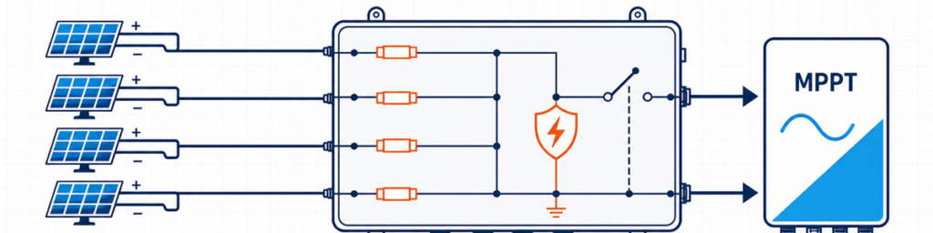
ヒューズ付きソーラーコンバイナーボックスを通じてインバーターのMPPT入力に接続された4本のPVストリングソーラーコンバイナーボックスは、1つのインバーター入力に接続される互換性のあるPVストリングの数、アレイの寒冷時最大開放電圧、Iscベースの設計電流の合計、およびその設置場所で必要な保護に適合する必要があります。入力数だけでは不十分です。4ストリングの場合、インバーターとケーブルレイアウトに応じて、4入力/1出力のボックスが1台、2入力/1出力の回路が2台、または外部コンバイナーがまったく不要な場合もあります。.
購入者にとって「4ストリング、1000 V」は使用可能な仕様のように聞こえます。見積を確認するエンジニアにとって、それは始まりに過ぎません。モジュールのデータシートには、寒い朝にストリングが1000 Vに近づくことが示されている場合があります。インバーターはストリングを2つの独立したMPPTに割り当てる場合があります。プロジェクトの電流係数を適用すると、出力経路は70 A近くを流す必要がある場合があります。これらの事実のいずれか1つでも、ボックスを変更する可能性があります。.
ここでの目的は、モジュールのデータシート、インバータースケジュール、単線結線図にすでに存在する情報を、防御可能な予備仕様に変換することです。一般的な構成と利用可能な製品オプションについては、以下を参照してください。 JUTRION PVコンバイナーボックスシリーズ.
屋根上のストリング数ではなく、インバーター図面から始める
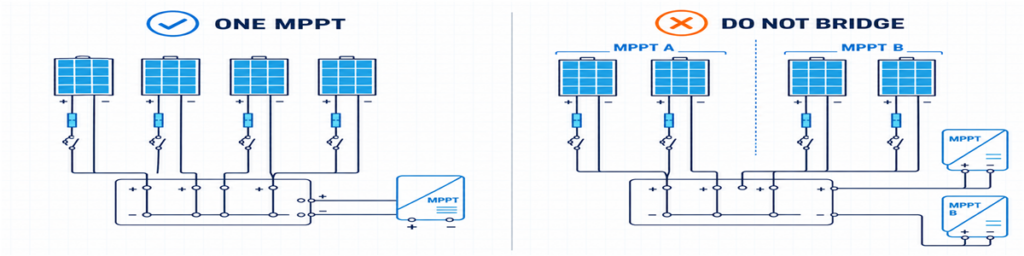
1つのMPPTに対する正しいPVストリンググループ化と、別々のMPPT入力を誤ってブリッジする場合の比較The strings entering one combiner output must have somewhere valid to go. That sounds obvious, yet it is where many early quotations go wrong.
屋根上に8本のストリングがあるとします。インバーター図面では、4本をMPPT Aに、4本をMPPT Bに割り当てています。8入力/1出力コンバイナーを要求すると、インバーターが独立して制御するように設計された2つの回路を結合することになります。実行可能な選択肢は通常、2つの別々の4入力/1出力グループ、電気的に独立した2つのセクションを含む1つの筐体、またはインバーターがすでに適切な入力と保護を備えている場合はストリングの直接接続です。.
並列運転を意図したストリングは、実際に互換性がある必要があります。モジュールタイプ、ストリングあたりのモジュール数、方位、予想される影を確認してください。ストリング長が異なると動作電圧が異なります。モジュールラベルが同一でも、強い影のあるストリングと影のないストリングを組み合わせると、動作の整合性が悪くなる可能性があります。.
これにより、最初の実用的なルールが得られます。
プロジェクト図面に見えるすべてのストリングではなく、1つの互換性のあるMPPT経路に割り当てられたストリングを数えます。.
外部コンバイナーの付加価値が小さい場合
多くのストリングインバーターは、すでに複数のDC入力、内部サージ保護、DC絶縁機能を備えています。各ストリングを適切なインバーター入力に直接配線できる場合、外部コンバイナーを追加すると、設計上の問題を解決せずに余分なケーブル終端が生じる可能性があります。.
単一ストリングボックスは関連するが異なるケースです。1入力/1出力ユニットは電流を合成せず、外部保護および絶縁ボックスとして機能します。これは、インバーターが遠隔にある場合、ローカル絶縁ポイントが必要な場合、またはアクセスしやすい場所に交換可能なサージ保護が必要な場合に役立ちます。.
1枚のシートに記載する価値のある5つの数値
ヒューズサイズや筐体寸法を検討する前に、5つの情報グループを収集します。ほとんどは発行済みのプロジェクト文書から直接コピーできます。.
| 情報 | 通常の入手元 | 変更される内容 |
|---|---|---|
| Voc、Isc、Imp、温度係数、最大直列ヒューズ | PVモジュールデータシート | 電圧、電流、ストリングヒューズの制限 |
| ストリングあたりのモジュール数と並列ストリング数 | ストリング構成表 | 入力数と総電圧/電流 |
| MPPT構成と入力制限 | インバータのデータシートと単線結線図 | どのストリングが出力を共有できるか |
| 最低温度、設置方法、暴露条件 | プロジェクト設計基準とサイトデータ | 低温時Voc、ディレーティング、筐体 |
| 対象国と適用規則 | プロジェクト仕様書 | 保護方式と文書化 |
見落とされがちな値の1つは、インバーターの最大許容短絡電流です。最大動作電流と最大短絡電流は互換性がありません。提案されたアレイは両方に対して確認する必要があります。.
対象国は電気的データと同じくらい重要です。IEC指向のプロジェクト向けに作成されたヒューズ計算に、北米の乗数をそのまま流用して普遍的なルールとして提示してはいけません。.
1000 Vまたは1500 Vを選ぶ前に低温時ストリング電圧を確認する
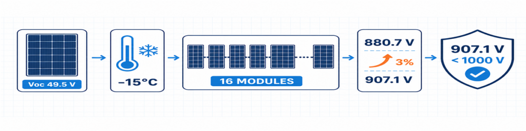
16モジュールの低温時PVストリングVoc計算。設計電圧は907.1 VモジュールのVocは通常、標準試験条件で示されます。セル温度が下がると上昇するため、想定される最低温度条件がストリング最大電圧を左右します。.
モジュールのデータシートに負のVoc温度係数が摂氏1度あたりのパーセントで記載されている場合、初期計算は次のようになります。
Voc、低温 = Voc、STC × [1 + |βVoc| × (25 − Tmin)]
Vstring、低温 = Voc、低温 × 直列モジュール数
係数は小数で入力してください。例えば、−0.28%/°Cは式では0.0028になります。モジュールメーカーが異なる低温方法を提供している場合は、代わりにその方法を使用してください。.
答えはインバーター以上に適合する必要があります。ヒューズリンクとホルダー、SPD、スイッチ断路器またはブレーカー、端子、導体、完成したアセンブリはすべて同じDC回路内にあります。SPDだけを1500 Vデバイスに交換しても、1000 Vボックスが1500 Vアセンブリになるわけではありません。.
未使用の電圧マージンは無駄な容量ではありません。実際に特定されたプロジェクト固有の温度基準と許容差を吸収します。避けるべきは、記録された根拠のない恣意的なマージンです。.
ストリングヒューズは習慣ではなく逆電流に依存する
並列ストリングが健全な場合、各ストリングは共通出力に電流を供給します。1つのストリングに障害が発生した場合、他のストリングがそのストリングに電流を逆流させる可能性があります。ストリングヒューズは、保護が必要な場所でその有害な逆電流を遮断するためにあります。.
他のストリングからの寄与の初期スクリーニングは次のとおりです:
I逆方向、画面 = (n − 1) × Isc、文字列
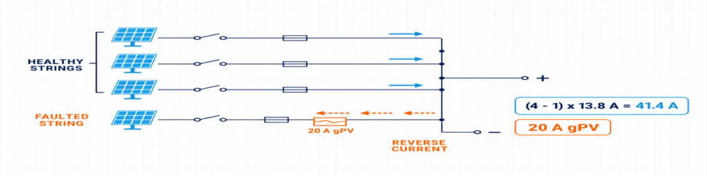
3つの健全なPVストリングから、20 A gPVヒューズで保護された故障ストリングへの逆電流ここで、nは並列ストリングの数です。この式は、2入力と4入力の間で答えが急速に変わる理由を示しています。4ストリンググループの故障ストリングは、3つの健全なストリングから電流を受ける可能性があります。.
この式を完成した保護設計として扱わないでください。選択されたgPVヒューズは、実際の筐体条件下で予想電流を流し、ケーブルと機器を保護し、モジュールの最大直列ヒューズ定格内に収まり、十分なPV DC電圧と遮断能力を備えている必要があります。ホルダーとヒューズは、温度とグループ化の影響を含めて一緒に確認されます。.
IEC 60269-6 は、1500 V DCまでの太陽光発電ストリングおよびアレイで使用されるヒューズリンクの補足要件をカバーしています。プロジェクトで採用された設置規則が、その製品の適用方法を決定します。.
オンラインで見られる1.56 × Iscの数値について
よく見かける1.56 × Iscという数値は、北米で一般的な設計経路で使われる2つの125%係数に関連するものです。これを普遍的なIECの計算式のように言い換えるべきではありません。プロジェクトがNECの適用を受ける場合は、採用されている版、機器の認定、および現地要件に従ってください。IEC準拠のプロジェクトであれば、関連するIECベースの据付規則、ならびにモジュール、ヒューズ、ケーブルの各メーカーの指示を適用してください。.
この区別は見積書に明記する価値があります。そうしないと、同じアレイデータを受け取ったにもかかわらず、2つのサプライヤーが異なるヒューズ定格を提示する可能性があります。.
合成経路は各入力とは別にサイズを決める
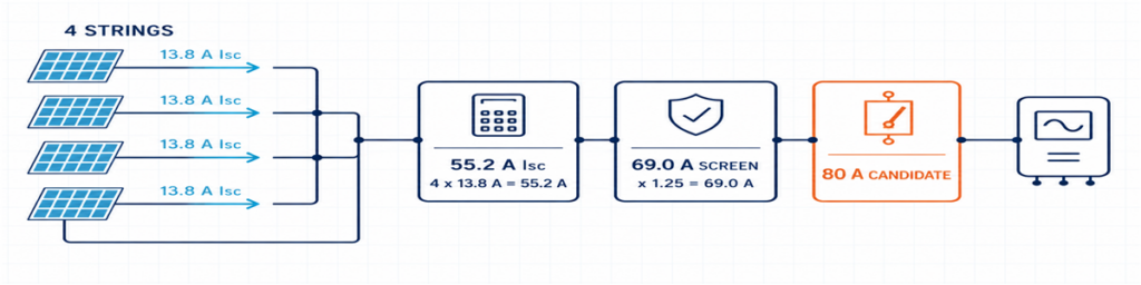
13.8 AのPVストリング4本を合成して55.2 A Iscとし、69 Aの設計スクリーニングと80 Aの出力機器候補を適用した例入力側と出力側では流れる電流が異なります。各入力には1ストリング分が流れ、共通出力には並列ストリングの合計が流れます。.
Isc,total = 並列ストリング数 × Isc、文字列
プロジェクトで要求される設計係数と補正係数は、その後、該当する導体と機器に適用されます。その結果は内部配線、ブスバー、端子、出力ケーブル、出力開閉機器に影響します。また、インバータの公表された制限値と比較する必要もあります。.
選定全体にImpだけを使うと、保護経路が小さすぎる可能性があります。インバータの通常MPPT電流を確認せずにIscだけを使うと、動作上の制限を見落とす可能性があります。各値を分けて扱い、それぞれに目的を持たせてください。.
| 値 | これを使って確認する項目 |
|---|---|
| ストリングImp | 通常動作電流とインバータMPPT適合性 |
| ストリングIsc | ストリング設計電流と過電流保護の計算 |
| 合計Isc | 合成経路とインバータ短絡電流制限 |
| 補正後のプロジェクト設計電流 | 据付条件下での導体、ブスバー、端子、出力機器 |
熱は、カタログ上は余裕に見える定格を覆すことがあります。密集して配置されたヒューズホルダー、端子損失、SPD、直射日光はすべて筐体内温度を上昇させます。基準条件で80 Aの機器が、すべての屋外ボックス内で自動的に80 Aのソリューションになるわけではありません。.
ヒューズ、アイソレーション、ブレーカー、SPDは役割が異なる
各コンポーネントに明確な役割が1つあれば、コンバイナボックスの仕様策定は容易になります。
- gPVヒューズ: 該当する逆過電流条件から個々のストリングを保護します。;
- スイッチディスコネクタ: PV DC定格の負荷開閉と明確なアイソレーション点を提供します。;
- DCサーキットブレーカー: 回路を開閉し、その特性とDC遮断定格が用途に適合する場合には過電流機能も提供します。;
- PV DC SPD: 過渡過電圧を制限するものであり、過電流保護やアイソレーションの代わりにはなりません。.
An output breaker is not mandatory simply because there is room for one. The system design may call for a switch-disconnector where overcurrent protection is already provided elsewhere, or for a breaker with a defined protective duty. Decide the function first.
The same principle applies to the SPD. Confirm the PV DC application, UCPV, protection modes, protection level, discharge-current duty, short-circuit behaviour and backup coordination. Type 2 is commonly used for induced surge conditions. Where an external lightning protection system or another lightning-current path is present, the arrangement may need Type 1 or Type 1+2 protection. See the JUTRION PV DC SPD range after the project voltage and lightning context are known.
For the isolating function, a device rated for the intended PV duty is more meaningful than a generic “DC switch” description. The JUTRION PV DC isolator range includes DC-PV2 options for review against the required voltage, current and pole arrangement.
A Four-String Example from Datasheet to Box
Illustrative example: This is a constructed commercial-rooftop case used to show the calculation. It is not a customer project or a universal design.
Four identical strings are assigned to one high-current inverter input. Each string contains 16 modules. The module datasheet gives Voc = 49.5 V, Isc = 13.8 A, βVoc = −0.28%/°C and a maximum series-fuse rating of 25 A. The project minimum temperature is −15°C. Its design basis also applies a stated 3% allowance after the temperature calculation.
The illustrative inverter has a 1000 V maximum DC input, an 80 A maximum input current and a 100 A maximum short-circuit current. No external lightning protection system is assumed.
The Drawing Points to Four Inputs and One Output
All four strings use the same modules and string length, and the inverter documentation permits them to feed the same input. A 4-in/1-out architecture is therefore appropriate at this stage. If the drawing divided them between two MPPTs, the answer would become two independent 2-in/1-out groups.
The Cold String Reaches 907.1 V
Cold module Voc = 49.5 × [1 + 0.0028 × (25 − (−15))] = 55.04 V
Cold string Voc = 55.04 × 16 = 880.7 V
Project design voltage = 880.7 × 1.03 = 907.1 V
A verified 1000 V assembly can pass this preliminary check, as can the illustrative inverter. The remaining margin is about 93 V. A seventeenth module would raise the result to approximately 964 V before the same allowance and would not pass this example after the allowance is applied.
Parallel Strings Make Individual Fusing Necessary
The other three strings can contribute an initial reverse-current screen of:
(4 − 1) × 13.8 = 41.4 A
これはモジュールの最大直列ヒューズ定格25 Aを上回るため、この例では個別のストリング保護が必要です。プロジェクト方式では、1.25 × 13.8 = 17.25 Aという予備的な下限ヒューズ電流値が得られます。20 AのgPVヒューズは、その値と25 Aのモジュール制限の間に位置します。採用する前に、そのホルダー、ケーブル保護、筐体温度、連続通電能力を確認する必要があります。.
The Common Output Needs More Than a 55.2 A Label
The combined short-circuit current is:
4 × 13.8 = 55.2 A
The example design basis uses 1.25 × Isc as its preliminary output-current screen:
1.25 × 55.2 = 69.0 A
80 AのPV DCスイッチ断路器は妥当な出発点の枠組みであり、自動的な最終選択ではありません。設置時の熱定格、電圧、極数、開閉責務は引き続き確認が必要です。インバータの100 A短絡制限は55.2 Aとの比較を満たします。その80 A動作制限は、実際のデータシートのモジュールImpの4倍と比較する必要があります。.
The preliminary box is now specific enough to review: four independently fused inputs, one combined output, 1000 V-class components throughout, a combined path designed around the stated 69 A screen, PV DC isolation and a Type 2 PV DC SPD subject to final coordination.
The Result on One Page
The calculation is easier to review when the assumptions, result and remaining check are kept together. This is also the point where a buyer can see whether two quotations are actually based on the same duty.
| Selection item | Illustrative result | What still needs confirmation |
|---|---|---|
| 構成 | 4 inputs / 1 output | All four strings feed one compatible inverter input |
| Maximum project voltage | 907.1 V | Site temperature basis, tolerance method and inverter limit |
| String protection | 20 A gPV preliminary selection | Fuse-holder temperature, cable protection and applicable rules |
| Combined short-circuit current | 55.2 A | Inverter maximum permissible short-circuit current |
| Preliminary output-current screen | 69.0 A | Correction factors and installed assembly temperature |
| Output isolation | 80 A frame is a starting candidate | PV DC duty, voltage, poles and installed current rating |
| Surge protection | Type 2 PV DC SPD initially | Ucpv, protection modes, LPS and backup coordination |
| 筐体 | Outdoor IP65 minimum | UV, corrosion, heat, glands and condensation |
Choosing Between a 1/1, 2/1 and 4/1 Configuration
JUTRION currently displays 1000 V DC, IP65 products in 1-in/1-out, 2-in/1-out and 4-in/1-out configurations. Use the input count to shortlist the architecture, then confirm the ratings that the project calculation produced.
| 構成 | Typical reason to shortlist it | Reason to stop and reconsider |
|---|---|---|
| 1 input / 1 output | One string needs an accessible protection and isolation point | No combining occurs; verify that a separate box adds a required function |
| 2 inputs / 1 output | Two matched strings feed one inverter input | The strings belong to separate MPPTs or exceed the combined-input limits |
| 4 inputs / 1 output | Four matched strings feed one suitably rated high-current input | The inverter needs two MPPT groups or the output path is underrated |
The worked example points toward a JUPV1000-4/1 architecture. It does not approve the internal fuse, output device or SPD by model name alone. Those parts have to be quoted against the 907.1 V project voltage, the proposed 20 A gPV string protection, the 69 A preliminary combined-current screen and the outdoor installation conditions.
Custom 1500 V or larger-string configurations deserve a fresh component and assembly check. They should not be treated as a label change to the 1000 V stock arrangement.
The Outdoor Enclosure Can Change the Current Rating
Electrical calculations are often completed in an office at 25°C. The box may spend its working life on a roof where the air is much hotter, direct sunlight warms the enclosure, and several fuse-holders carry current side by side. That difference affects more than comfort during maintenance.
Heat is produced at fuses, terminals, conductors, the SPD and the output device. Closely packed components have less opportunity to cool, while a sealed enclosure restricts air exchange. A component that carries its marked current under its reference conditions may require derating in the final assembly. This is why the 80 A switch-disconnector in the example remains a starting frame until the installed arrangement has been checked.
IP65 is useful, but it answers only an ingress-protection question. It does not automatically establish:
- resistance to long-term ultraviolet exposure;
- corrosion performance near the coast or in an industrial atmosphere;
- acceptable internal temperature under full current and solar loading;
- condensation control during daily heating and cooling;
- suitability of cable glands, seals and materials for the installed cables;
- insulation performance at high altitude.
Mounting details also matter. Cable entries made through the top of an outdoor enclosure create a different water path from bottom entry. Undersized glands may damage seals or leave insufficient cable support. Tight cable bends can transfer mechanical force to fuse-holders and terminals. The enclosure should be reviewed as an installed assembly, not as an empty plastic or metal box with an IP number.
IEC 61439-2:2020 covers power switchgear and controlgear assemblies up to 1500 V DC. The relevance here is practical: using individually rated components does not remove the need to verify the completed assembly, including temperature rise, dielectric properties, protective circuits, clearances, wiring and mechanical construction as applicable.
Send Enough Information for the Supplier to Check the Result
A short technical enquiry is more useful than a long purchasing template. Attach the module and inverter datasheets and state:
- strings per output and modules per string;
- module Voc, Isc, Imp, βVoc and maximum series fuse;
- minimum design temperature and any voltage allowance;
- inverter MPPT arrangement and input limits;
- calculated maximum voltage and combined design current;
- required fuse, isolation, breaker and SPD functions;
- enclosure location, IP requirement, ambient, UV and corrosion exposure;
- cable sizes, monitoring, destination market and quantity.
For the illustrative project, that becomes: 4-in/1-out, four identical 16-module strings feeding one MPPT, 907.1 V stated project design voltage, preliminary 20 A gPV fuses, 55.2 A total Isc, 69 A preliminary output-current screen, PV DC isolation, coordinated Type 2 PV DC surge protection and an outdoor enclosure.
Why Two “4-String, 1000 V, IP65” Quotations May Not Be Equivalent
One quotation may use gPV fuse-links and holders verified for the intended voltage and temperature. Another may list only a nominal fuse current. One box may provide a load-break switch-disconnector; another may use a device intended mainly for isolation. SPD Ucpv, protection modes, short-circuit behaviour and replaceability may also differ even when both quotations say “Type 2 SPD.”
The common output is another source of hidden difference. Compare the installed current capability of the busbars, conductors, terminals and output device, not only the largest ampere number printed in the bill of materials. Also check terminal capacity against the actual outgoing cable. A technically lower-priced quotation is not cheaper if it requires replacement glands, a larger enclosure or rework at site.
A useful comparison therefore normalizes the following items before price:
- input/output arrangement and MPPT grouping;
- maximum DC voltage of the complete path;
- string-fuse class, rating and module limit;
- combined current and installed temperature conditions;
- output device function and DC duty;
- SPD type, Ucpv, modes and coordination;
- terminal and cable-gland capacity;
- enclosure material and environmental suitability.
The final selection should read as one connected electrical path. If the quotation confirms only input count, nominal voltage and IP rating, it has not yet answered the sizing question.
Verify the Box After Installation
A correct design can still be compromised by reversed polarity, loose terminations, damaged glands or a string connected to the wrong input. Commissioning should follow the project procedure and component instructions, with the DC circuit isolated and tested by qualified personnel.
Before energizing the combined output, record:
- string identity, polarity and measured open-circuit voltage;
- whether measured string voltages are reasonably consistent with the design and with one another;
- terminal tightening completed to the specified torque;
- protective-conductor and bonding continuity where required;
- fuse type and rating in every populated way;
- SPD status indication and remote alarm contact, if fitted;
- operation and position indication of the isolating device;
- labels, unused-entry seals, gland compression and enclosure closure.
After the system has operated under representative load, inspect for abnormal heating, discoloration, odour, nuisance fuse operation or moisture. Where the project maintenance plan uses thermography, the baseline image is more useful when load and ambient conditions are recorded with it. The purpose is not to “prove” the design from one scan, but to leave a reference for later comparison.
IEC 62548-1:2023 provides the broader IEC design context for PV arrays, including DC wiring, protection, switching and earthing. The completed assembly also needs appropriate verification; IEC 61439-2:2020 covers power switchgear and controlgear assemblies up to 1500 V DC. PV DC SPD requirements are addressed by IEC 61643-31.
To compare the result with a JUTRION configuration, send the string schedule, module and inverter data, site temperature, protection requirements and destination standard through the PV combiner box page. That gives both sides something more reliable to discuss than “four strings, best price.”
よくある質問
How Many Solar Strings Require a Combiner Box?
There is no universal minimum. An external combiner is useful when compatible strings need to be paralleled before one inverter input, when it reduces long cable runs, or when the project needs a centralized location for fuses, isolation, surge protection or monitoring. If an inverter already accepts every string directly and provides the required functions, a separate combiner may not be necessary.
What Size Fuse Should Be Used in a Solar Combiner Box?
Select a PV-rated gPV fuse from the string Isc, applicable installation method, cable capacity, environmental conditions and module maximum series-fuse rating. The fuse must carry expected current without nuisance operation while remaining low enough to protect the module and cable. Do not apply 1.56 × Isc as a universal IEC rule; the calculation depends on the destination standard.
Can Strings Connected to Different MPPTs Share One Combiner Box?
They may share a physical enclosure only if the MPPT circuits remain electrically separate. Do not combine the outputs of independent MPPT groups unless the inverter manufacturer explicitly permits that architecture. Each group should have its own compatible strings, output path and ratings.
Do I Need a 1000V or 1500V PV Combiner Box?
Calculate the maximum cold-weather open-circuit voltage of the complete string and include the allowances required by the project method. Select a voltage class that keeps the inverter and every component in the combiner path within rating. A 1500 V SPD alone does not make the completed box suitable for 1500 V.
What Is the Difference Between a PV Combiner Box and a PV Protection Box?
A PV combiner box joins two or more compatible string inputs into a common output. A 1-in/1-out PV protection box does not combine strings; it provides a convenient location for functions such as isolation, surge protection or overcurrent protection on one string circuit.
