

Trả lời nhanh: Bạn cần công tắc chuyển mạch tự động cỡ nào?
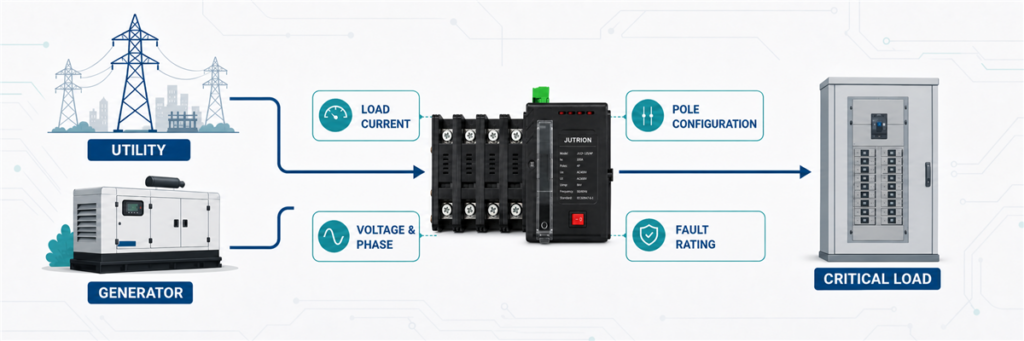
Công tắc chuyển mạch tự động phải chịu được dòng điện cao nhất có thể đi qua nó từ một trong hai nguồn. Hãy tính dòng điện đó từ tải được chuyển mạch, không chỉ từ nhãn máy phát, sau đó chọn định mức ATS phù hợp tiếp theo. Trước khi đặt hàng, cũng cần xác nhận điện áp, pha, số cực, chuyển mạch trung tính, khả năng chịu ngắn mạch, phương thức chuyển tiếp, chức năng bộ điều khiển và tiêu chuẩn áp dụng.
Máy phát 100 kVA không tự động yêu cầu công tắc chuyển mạch 100 A. Ở điện áp 400 V ba pha, 100 kVA tương ứng với khoảng 144 A. Ở điện áp 230 V một pha, cùng công suất biểu kiến đó sẽ tương ứng với khoảng 435 A. Con số công suất giữ nguyên. Dòng điện thì không.
Đó là lý do việc định cỡ công tắc chuyển mạch tự động bắt đầu từ sơ đồ một sợi và tải được chuyển mạch. Định mức máy phát chỉ là một đầu vào. Nó không phải là toàn bộ câu trả lời.
Trước tiên hãy xác định ATS sẽ thực sự mang tải gì
Trước khi dùng công thức, hãy vẽ ranh giới quanh phía tải của ATS. Điều này tránh lỗi định cỡ phổ biến nhất: tính toán một phần của hệ thống trong khi chỉ định công tắc cho phần khác.
ATS có thể chuyển mạch:
- toàn bộ dịch vụ hạ thế hoặc tủ phân phối chính;
- thanh cái khẩn cấp hoặc an toàn tính mạng chuyên dụng;
- bảng phụ tải chọn lọc cấp cho máy bơm, chiếu sáng, điều khiển, làm lạnh hoặc thiết bị CNTT;
- một máy hoặc quy trình công nghiệp;
- đầu ra của máy phát, bộ biến tần hoặc nguồn điện lưới thứ hai.
Giả sử một tòa nhà có dịch vụ chính 800 A nhưng chỉ có bảng tải thiết yếu 250 A được dự phòng. ATS lắp trên bảng thiết yếu đó không tự động là thiết bị 800 A. Yêu cầu dòng điện liên tục của nó theo mạch được chuyển mạch, tuân theo các quy tắc thiết kế chi phối và bố trí thiết bị bảo vệ.
Vấn đề ngược lại cũng xảy ra. Máy phát có thể nhỏ hơn dịch vụ điện lưới, nhưng ATS vẫn nằm trên đường nguồn bình thường và liên tục mang tải đã chọn khi có điện lưới. Có thể cần cắt tải hoặc bảng tải thiết yếu nếu máy phát không thể cấp cho mọi thứ kết nối phía hạ lưu. Công tắc không thể làm cho máy phát quá nhỏ mang thêm tải.
Lập bảng đầu vào định cỡ trước khi bạn tính toán
Định cỡ ATS tốt bắt đầu bằng một danh sách ngắn các đầu vào đã được xác minh. Nếu một số mục chưa biết, hãy đánh dấu chúng là điểm mở thay vì che giấu sau hệ số an toàn lớn. Việc tăng khung ampe không thể sửa được bố trí trung tính không phù hợp, định mức chịu sự cố thấp hoặc bộ điều khiển không thể giao tiếp với máy phát.
| Đầu vào | Tại sao nó quan trọng | Nơi xác minh |
|---|---|---|
| Tải được chuyển mạch | Xác định dòng điện mà ATS phải mang | Bảng tải, sơ đồ một sợi, nhu cầu đo được |
| Nguồn bình thường và nguồn thay thế | Xác định bố trí nguồn và trình tự bộ điều khiển | Sơ đồ một sợi và dữ liệu máy phát/bộ biến tần |
| Điện áp và tần số | Đặt yêu cầu cách điện, cảm biến và bộ điều khiển | Thông số kỹ thuật dự án và nhãn nguồn |
| Hệ thống một pha hoặc ba pha | Thay đổi công thức dòng điện và cấu hình cực | Bản vẽ phân phối |
| Công suất tính bằng A, kW hoặc kVA | Xác định phương pháp tính toán nào hợp lệ | Danh sách tải, dữ liệu máy phát, nhãn thiết bị |
| Hệ số công suất và hiệu suất | Cần thiết khi chuyển đổi một số giá trị kW sang dòng điện | Dữ liệu thiết bị hoặc máy phát |
| Tải động cơ và máy biến áp | Ảnh hưởng đến trình tự chuyển mạch, dòng khởi động và phản ứng nguồn | Danh sách động cơ và nghiên cứu khởi động |
| Dòng sự cố khả dụng | Đặt ra khả năng chịu đựng và đóng cắt yêu cầu | Nghiên cứu ngắn mạch |
| Thiết kế nối đất và trung tính | Xác định xem trung tính liền hay trung tính chuyển mạch là phù hợp | Nghiên cứu nối đất và quy tắc lắp đặt địa phương |
| Môi trường xung quanh và vỏ tủ | Có thể ảnh hưởng đến độ tăng nhiệt, giảm công suất và dòng sản phẩm | Dữ liệu hiện trường và hướng dẫn của nhà sản xuất |
For an existing facility, measured demand can be more useful than adding every connected nameplate. A plant may have 600 kW of connected equipment but never operate all of it simultaneously. Conversely, a short measurement taken during a light production shift may understate the real maximum. Use a representative demand record, the operating schedule, and planned expansion together.
For a new facility, the load schedule should identify which loads are continuous, intermittent, mutually exclusive, or shed during generator operation. This is the point where electrical design and operational priorities meet. The ATS should serve the intended emergency system, not an imaginary condition in which every connected device runs at full load forever.
Convert the Available Project Data into Amps
Use current directly when a verified maximum design current is already available. If the project gives power in kW or kVA, convert it using the correct system voltage and phase arrangement.
When the Input Is kVA
Apparent power in kVA already includes the effect of power factor, so do not divide by power factor a second time.
Single-phase:
I = S × 1,000 / V
Three-phase:
I = S × 1,000 / (√3 × VLL)
Here, I is line current in amperes, S is apparent power in kVA, V is single-phase voltage, and VLL is three-phase line-to-line voltage.
When the Input Is kW
Real power requires a power-factor assumption. If the kW figure is mechanical output from a motor rather than electrical input, efficiency also matters.
Single-phase electrical load:
I = P × 1,000 / (V × PF)
Three-phase electrical load:
I = P × 1,000 / (√3 × VLL × PF)
For a motor specified by shaft-output kW, divide by efficiency as well. Use nameplate current where possible because it reflects the actual motor design better than a generic efficiency estimate.
| Available input | What to use | Common mistake |
|---|---|---|
| Verified load current in A | Use the design current directly | Converting it back to power and adding new assumptions |
| Generator or load rating in kVA | Use the kVA formula for the correct phase and voltage | Dividing by power factor twice |
| Electrical load in kW | Use voltage, phase, and a justified power factor | Assuming PF = 1 for a mixed commercial or industrial load |
| Motor output in kW | Prefer nameplate current; otherwise include PF and efficiency | Treating mechanical output as electrical input |
| Main breaker rating only | Check whether the ATS carries the full service or a selected-load feeder | Automatically copying the main-breaker frame onto every ATS |
Connected Load, Maximum Demand, and Source Capacity
These three values can be different, and each answers a different question.
Connected load is the sum of equipment that could be connected. It is useful for understanding the system but can overstate simultaneous current when loads operate at different times.
Maximum demand is the highest credible simultaneous load under the defined operating condition. This is often the most relevant starting point for the ATS continuous-current requirement.
Source capacity is what the utility, generator, transformer, inverter, or battery system can deliver. The alternate source may be deliberately smaller than the connected load when priority controls shed nonessential circuits.
Consider a hotel with 420 A of connected emergency-side equipment. The operating study shows that fire pumps, evacuation lighting, security, and selected elevators create a maximum transferred demand of 285 A. The generator is rated for 350 A, and the controls prevent comfort HVAC from connecting during an outage. A 400 A ATS may be a defensible starting point. Adding all 420 A without recognizing the control sequence could push the project into a larger, more expensive frame. Using only the 350 A generator rating would miss the reason the system works.
The load-management sequence must be reliable and documented. If the controls fail and all 420 A can connect, the smaller source may be overloaded even though the ATS itself can carry the current. ATS sizing and generator sizing are connected, but they are not the same calculation.
Three Worked ATS Sizing Examples
Example 1: A Single-Phase Essential-Load Panel
Consider an illustrative small commercial site with a 230 V single-phase essential-load panel. The calculated simultaneous load is 11.5 kVA.
I = 11.5 × 1,000 / 230 = 50 A
The calculated current is 50 A. The correct purchasing decision is not simply “buy a 50 A ATS.” Check the continuous loading expected by the installation rules, the available product ratings, cable and protective-device ratings, and any planned load growth. If the verified requirement exceeds 50 A after those checks, a 63 A frame may be the practical selection.
A compact JUTRION automatic transfer switch may suit this type of selected-load application, but the exact model still has to match the source voltage, pole arrangement, controller logic, and short-circuit conditions.
Example 2: A 100 kVA, 400 V Three-Phase Generator
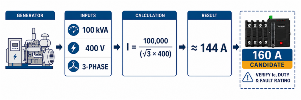
Tính toán kích thước ATS ba pha cho máy phát 100 kVA 400 V cho kết quả khoảng 144 A.A commercial building uses a 100 kVA standby generator at 400 V, three-phase. The ATS transfers a dedicated emergency board that the generator is intended to supply.
I = 100 × 1,000 / (√3 × 400)
I ≈ 144 A
A 125 A ATS would be too small for the generator’s rated apparent-power output. The next suitable standard rating could be 160 A, provided the transferred-load calculation, operating duty, product data, and installation rules support it.
Now change one assumption. If the emergency board’s verified maximum demand is only 105 A and load management prevents additional circuits from connecting during generator operation, the engineer may size around that controlled load rather than the theoretical output of the generator. That decision must be documented in the system design. A supplier should not infer it from the generator nameplate.
This case also shows why an ATS can be rated higher than the generator. A 160 A switch connected to a source capable of 144 A is not inherently a mismatch. The switch rating is a carrying limit, not a command that forces 160 A from the generator.
Should the ATS Match the Generator or the Main Breaker?
There is no universal “match the larger nameplate” rule. Follow the current path.
If the ATS is installed at a full-service transfer point, it may carry the normal-source service load whenever the utility is available. The generator can still be smaller if the system has approved load management, but the transfer equipment and distribution architecture must suit the full normal path.
If the ATS feeds a separate essential-load board, its rating can follow that feeder’s calculated demand and design rules rather than the building’s main service rating. This is common when only critical circuits require backup power.
If the ATS is packaged with a generator for one dedicated machine, the generator current, machine demand, starting behavior, and feeder protection may all be close. Even then, verify the voltage, phase, fault current, and controller interface instead of selecting by kVA alone.
| ATS location | Primary sizing basis | Important secondary check |
|---|---|---|
| Full-service transfer | Maximum current through the service path | Service rules, generator load management, fault current |
| Essential-load subpanel | Calculated demand of selected circuits | Feeder protection and load-shedding logic |
| Dedicated machine or process | Machine operating current | Starting duty and acceptable interruption |
| Generator output switch | Generator rated current and connected transferred load | Overload protection and future parallel/source plans |
| Utility-to-utility transfer | Load current carried from either utility source | Source independence and transition permission |
A larger ATS can be used with a smaller generator when the electrical ratings and protection are coordinated. A smaller ATS cannot be justified merely because the generator is smaller if the switch carries a higher utility-side load during normal operation.
Example 3: A Motor-Heavy Industrial Emergency Bus
An industrial emergency bus has 180 A of running load, including pumps and ventilation motors. Selecting a 200 A ATS may appear sufficient. The harder question is what happens during transfer.
Motor loads can retain voltage after disconnection. If a second source is connected while the residual voltage is out of phase, the electrical and mechanical stress can exceed normal running conditions. Generator voltage and frequency may also dip when several motors restart together.
Do not solve this by applying a universal “motor load × 1.5” rule. That shortcut mixes three different decisions:
- the continuous current the ATS contacts must carry;
- the making and utilization duty of the switching equipment;
- the generator’s ability to accept starting kVA and voltage dip.
A better design may use staged restarting, load shedding, a delayed-transition neutral position, or in-phase transfer. A neutral delay can allow residual voltage from inductive loads to decay before the alternate source is connected. The chosen ATS and controller must support the required sequence.
For this project, the ampere frame cannot be finalized until the motor-starting study, transfer sequence, generator response, and upstream protection are reviewed. The honest preliminary answer is “at least the verified continuous-load requirement, then confirm the transfer duty.”
How Load Type Changes the Decision After the Amp Calculation
Two projects can have the same 250 A running current and need different transfer solutions. The difference lies in what the load does when voltage disappears and returns.
Resistive Heating and Lighting
Predominantly resistive loads usually have a straightforward relationship between power and current. The main questions are simultaneity, continuous duty, and source capacity. Some lighting systems, however, include electronic drivers with high inrush or harmonic current, so the label “lighting” is not enough.
Motors, Pumps, Compressors, and Fans
Motors create starting kVA, residual voltage, and possible phase-angle stress during transfer. The system may restart motors sequentially rather than all at once. A delayed transition can provide time for residual voltage to decay, while in-phase transfer controls can wait for a suitable phase relationship. The correct approach depends on the process and equipment.
Transformers
Transformer energization can produce a high magnetizing inrush that varies with residual flux and the point on the voltage waveform at closing. A transfer that is acceptable for steady-state transformer current may still cause a severe source voltage dip or nuisance operation of protection. Review the transformer and generator study rather than applying a generic current margin.
UPS, Data-Center, and Electronic Loads
Electronic loads can be sensitive to interruption time and source quality. They may also draw nonlinear current. A UPS can bridge an open-transition gap, but the generator and ATS controller must allow the alternate source to stabilize. Transfer thresholds that are too narrow can cause repeated switching when generator voltage or frequency hunts near the acceptance limit.
Fire Pumps and Life-Safety Loads
These systems are governed by application-specific rules and project requirements. They are not ordinary motor feeders. The current IEC 60947-6-1:2026 edition includes specific provisions for transfer switching equipment used with electric-driven fire-pump control equipment. Treat the complete approved system, controller, source, and installation rules together.
Select the Next Suitable ATS Rating, Not the Nearest Number
Once the design current is established, compare it with available product ratings. Never round down. Also avoid oversizing without a reason. A much larger ATS may increase enclosure size, cable-termination requirements, panel cost, and spare-parts burden without improving system performance.
| Calculated current | Possible next frame | What must still be checked |
|---|---|---|
| 28 A | 32 A or the next offered rating | Continuous duty, conductor and protective-device coordination |
| 50 A | 63 A where required by the verified design basis | Load growth, terminals, enclosure, pole configuration |
| 144 A | 160 A | Actual transferred load, source capacity, fault rating |
| 365 A | 400 A | Temperature, bus/cable arrangement, transfer duty |
| 1,420 A | 1,600 A | High-current switch architecture, protection, maintenance strategy |
These are illustrative mappings, not a substitute for a model-specific catalogue. JUTRION offers ATS solutions across a broad current range, but availability, class, poles, controller, and test ratings vary by series.
Check Rated Operational Current and Utilization Category
The number printed as a frame or thermal-current rating is not always the current the device can switch under every load condition. For an IEC project, verify the model’s rated operational current, Ie, at the project voltage and for the applicable utilization category.
IEC transfer switching equipment may be marked with categories such as AC-31, AC-32, or AC-33. The category reflects the type of load and switching duty used to establish the rating. Motor and mixed inductive loads can impose a more demanding making and breaking duty than predominantly resistive loads. A product that carries its full frame current in one category may have a lower Ie in another.
This changes the selection sequence. If the calculation gives 365 A, a nominal 400 A frame is only a candidate. The relevant data table must also show an Ie of at least 365 A at the system voltage and required utilization category. If it does not, move to a larger frame or a product designed for that duty.
| Result from the calculation | Preliminary frame | Next decisive check |
|---|---|---|
| 50 A at 230 V single-phase | 63 A candidate | Ie at 230 V, load duty, poles, and continuous operating condition |
| 144 A at 400 V three-phase | 160 A candidate | Ie at 400/415 V for the required utilization category |
| 365 A motor-heavy load | 400 A candidate | AC-33 duty, restart sequence, generator response, and product data |
This is the missing bridge between a power-system calculation and a real catalogue selection. The formula produces a required current. The manufacturer’s tested Ie confirms whether a particular model can perform that duty.
Check Temperature, Enclosure, Terminals, and Installation Duty
Catalogue current is tied to stated conditions. A switch installed in a cool, ventilated electrical room does not experience the same thermal environment as a sealed outdoor cabinet exposed to sun, dust, salt, or high ambient temperature.
Confirm the permitted ambient range and any manufacturer derating. Do not assume that choosing the next frame automatically guarantees full current at an elevated temperature. Enclosure construction, ventilation, busbar arrangement, cable size, number of conductors per terminal, and internal heat from adjacent equipment all affect the final assembly.
Terminal capacity deserves early attention on high-current projects. A 1,600 A ATS may require multiple parallel cables or bus connections per phase. The panel builder needs the approved conductor range, lug arrangement, bending space, entry direction, torque values, and neutral capacity. An electrically adequate switch that cannot accept the specified cables is not a usable selection.
Frequency of operation also matters. An ATS used only during occasional utility outages has a different operating profile from a generator-to-generator remote site that alternates sources on a schedule. Mechanical and electrical endurance data, maintenance access, spare parts, and bypass requirements become more important as transfer frequency and the cost of downtime increase.
Ampere Rating Is Only the First Gate
A correctly calculated current can still lead to the wrong ATS. Complete the following checks before issuing a purchase specification.
1. Match Both Sources for Voltage, Phase, and Frequency
The ATS and its controller must be suitable for the normal source, alternate source, and load. Confirm nominal voltage, allowable sensing range, single-phase or three-phase arrangement, phase sequence, and frequency. For a generator source, confirm the controller does not transfer until voltage and frequency are stable.
2. Decide Whether the Neutral Must Be Switched
A three-phase, three-pole ATS switches the phase conductors and normally leaves a solid neutral. A four-pole ATS switches the neutral as a fully rated pole. Switched-neutral arrangements are commonly considered with separately derived sources, but “use 4P for every generator” is not a safe universal rule.
The decision depends on the grounding and bonding design, source arrangement, residual-current protection, local rules, and how neutral current paths behave in normal and emergency operation. Have the system designer confirm this point. It cannot be settled by the ampere formula.
3. Choose the Transfer Equipment Class and Protection Architecture
A PC-class transfer switch is primarily a transfer device. It generally relies on coordinated upstream overcurrent protection. A CB-class arrangement uses circuit-breaker-based switching devices and may integrate overload and short-circuit interruption functions, depending on the tested assembly.
Do not select the class from speed or price alone. Ask who is responsible for clearing a downstream fault, which protective device is upstream, and whether the complete combination has the required ratings. JUTRION’s MCCB range and high-current ACB system guide provide useful context for the protective side of that decision.
4. Check IEC Short-Circuit Ratings or UL WCR
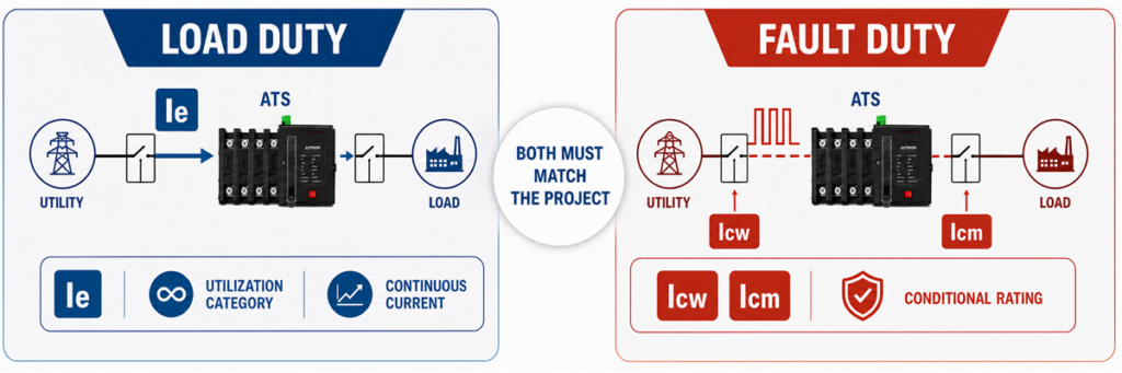
So sánh dòng điện vận hành định mức Ie của ATS với các thông số ngắn mạch Icw, Icm và định mức có điều kiện.A 400 A current rating tells you how much load current the ATS can carry under its rated conditions. It does not tell you that the switch can survive a 50 kA fault at its installation point.
For an IEC project, review the short-circuit values marked for the transfer switching equipment. Depending on the product and protection arrangement, these can include rated short-time withstand current Icw, rated short-circuit making capacity Icm, or a conditional short-circuit rating tied to a specified upstream protective device. The time value and protection conditions matter as much as the current value.
For a North American application, the withstand and closing rating WCR must be adequate for the available fault current at the ATS location under its marked conditions. A WCR can depend on a particular fuse or circuit breaker and its clearing time.
In either system, use the model-specific coordination information. The breaking capacity printed on an upstream MCCB cannot simply be copied into the ATS specification; the two devices perform different jobs during a fault.
5. Select the Transition Method Around the Load
Open transition is break-before-make: the first source disconnects before the second connects. Delayed transition adds an intentional off interval. Closed transition briefly parallels acceptable sources and introduces additional controls and utility requirements.
Most applications do not choose a transition method by current rating. They choose it by load behavior, interruption tolerance, residual voltage, generator response, and source-paralleling rules.
6. Specify the Controller and Project Interfaces
A utility-to-generator system normally needs more than voltage sensing. Check generator start and stop contacts, start delay, source-available settings, transfer delay, retransfer delay, cool-down time, manual operation, test functions, alarm contacts, and remote indication.
Industrial and critical-power projects may also need RS485/Modbus communication, event logging, load shedding, fire-system interfaces, or a bypass-isolation arrangement. These features can change the series and enclosure even when the ampere rating stays the same.
Use This Nine-Step Automatic Transfer Switch Sizing Process
- Mark the ATS boundary on the one-line diagram. Identify every circuit that remains downstream in normal and emergency operation.
- Establish the maximum credible transferred demand. Use measured data or a documented load schedule, not an unexplained sum or a light-load snapshot.
- Convert power to current correctly. Distinguish amperes, kW, and kVA; use the correct single- or three-phase formula.
- Check the alternate source. Confirm that the generator, inverter, or second utility source can supply the intended load and starting sequence.
- Select the next suitable current rating. Use the verified design basis and available product frames. Never round down.
- Review load behavior during transfer. Address motor residual voltage, transformer inrush, UPS ride-through, load shedding, and restart order.
- Complete the electrical configuration. Specify voltage, frequency, poles, neutral treatment, PC/CB architecture, and transition method.
- Verify fault and protection coordination. Compare the marked withstand/closing performance with available fault current and the upstream protective device.
- Finish the project specification. Add controller functions, communications, enclosure, terminals, ambient conditions, applicable standard, quantity, and destination market.
This sequence intentionally separates calculation from verification. It lets a buyer obtain a fast preliminary size without pretending that the result alone authorizes installation.
Keep the calculation record with the quotation. At minimum, record the source of the load data, the date or operating condition represented by any measurements, the diversity assumptions, the formula used, and the reason for choosing the final frame. If a later project revision adds a pump, changes the generator voltage, or moves the ATS to a different point on the one-line diagram, the team can see immediately whether the original result is still valid. Without that record, a frame size often survives through several drawing revisions even after the assumptions behind it have changed.
IEC 60947-6-1:2026 and UL 1008 Are Not Interchangeable Labels
The current IEC edition is IEC 60947-6-1:2026. It applies to transfer switching equipment used to transfer loads between power sources up to 1,000 V AC or 1,500 V DC. The 2026 edition covers manually, remotely, and automatically operated equipment and adds specific treatment for areas including bypass/isolation equipment, closed-transition ATSE, standalone ATS controllers, and fire-pump transfer switching equipment.
For North American projects, UL Solutions identifies UL 1008 as the standard used for automatic transfer switches in emergency and optional standby systems, as well as nonautomatic transfer switches. Installation requirements also depend on the applicable electrical code, project classification, and authority having jurisdiction.
An ampere calculation is useful in either market. It does not prove that a specific ATS is certified, listed, or approved for that project. Confirm the exact model, standard, voltage, short-circuit rating, and installation conditions before ordering.
Why Two ATS Units with the Same Amp Rating May Not Be Equivalent
The ampere rating is only one line on the nameplate. Two 400 A transfer switches may carry the same normal load current while using different switching mechanisms, neutral arrangements, protection architectures, controllers, and short-circuit ratings.
Five checks reveal most of the meaningful differences:
- Transfer architecture: A PC-class device normally depends on coordinated upstream protection, while a CB-class design uses circuit-breaker-based switching and may include overcurrent functions.
- Number of poles: A three-pole unit normally retains a solid neutral. A four-pole unit switches the neutral and must suit the grounding design.
- Fault performance: The marked short-circuit withstand and closing capability must match the available fault current and the specified upstream protective device.
- Controller functions: Source sensing, generator contacts, adjustable delays, event records, communication, and load-control functions vary widely.
- Applicable evidence: Voltage, utilization duty, ambient conditions, IEC or UL requirements, and model-specific test documentation must match the project.
These are system differences, not optional sales extras. A basic PC-class ATS may be the correct answer for a coordinated distribution panel. A critical facility may need delayed transition, advanced monitoring, or bypass isolation. Neither product is automatically better because it has more functions. The correct device is the one whose tested configuration matches the one-line diagram and operating sequence.
Record the Result as a Complete Preliminary Specification
After the calculation, write down the assumptions and the remaining checks. A preliminary specification should identify the transferred load, calculated current, proposed frame, voltage, phase, frequency, source arrangement, poles, transition method, protection architecture, controller interfaces, installation environment, and applicable standard.
This record makes the engineering review easier and prevents a frame size from being separated from the assumptions behind it. It also creates a clean handoff between the system designer, panel builder, generator supplier, and ATS manufacturer.
Once those inputs are confirmed, compare them with the available configurations in the JUTRION automatic transfer switch range. Final model selection should be based on the model-specific ratings and project conditions, not on current alone.
The practical order is simple: define what the ATS will carry, calculate the current, verify Ie for the actual utilization category, and then complete the pole, transition, controller, and short-circuit checks.
