

Trả lời nhanh: Tại sao Bộ chuyển mạch tự động không chuyển sang máy phát điện?
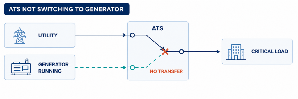
Bộ chuyển mạch tự động không chuyển sang máy phát điện trong khi máy phát điện đang chạyNếu bộ chuyển mạch tự động không chuyển sang nguồn máy phát điện, hãy tìm bước đầu tiên bị lỗi trong chuỗi chuyển mạch. Xác nhận xem ATS có phát hiện nguồn điện lưới không đạt yêu cầu hay không, có phát lệnh khởi động động cơ hay không, có nhận được điện áp và tần số máy phát đạt yêu cầu hay không, có hoàn thành độ trễ đã lập trình hay không, có vận hành cơ cấu chuyển mạch hay không và có trả về phản hồi vị trí chính xác hay không. Trạng thái thiếu đầu tiên thường xác định khu vực lỗi.
Máy phát điện đang chạy không chứng minh rằng ATS đã sẵn sàng chuyển mạch. Bộ ngắt mạch đầu ra của máy phát có thể đang mở, điện áp hoặc tần số có thể vẫn nằm ngoài cửa sổ chấp nhận của bộ điều khiển, có thể thiếu một pha, có thể thiếu một đầu vào cho phép, hoặc cơ cấu có thể bị lỗi sau khi bộ điều khiển phát lệnh. Việc khắc phục sự cố trở nên nhanh hơn khi các điều kiện này được kiểm tra theo trình tự thay vì thay bộ điều khiển trước tiên.
Ranh giới an toàn: vỏ tủ ATS có thể chứa dây dẫn điện lưới và máy phát có điện cùng lúc. Người vận hành có thể ghi lại các chỉ báo, cảnh báo và sự kiện của bộ điều khiển mà không cần mở các ngăn đang có điện. Việc đo điện áp, kiểm tra thông mạch, vận hành cơ cấu bằng tay và kiểm tra bên trong phải tuân theo hướng dẫn sử dụng thiết bị đã đặt hàng, quy trình chuyển mạch tại hiện trường và các quy tắc an toàn điện hiện hành, và chỉ nên được thực hiện bởi nhân sự có trình độ.
Đọc lỗi như một chuỗi chuyển mạch bị đứt đoạn
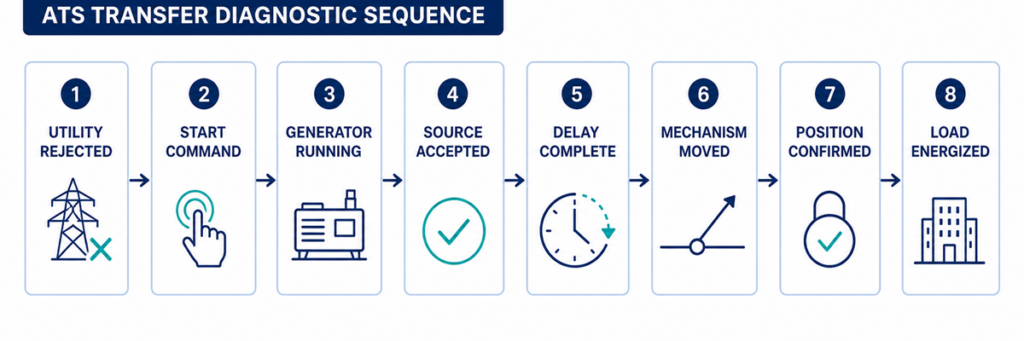
Trình tự chẩn đoán ATS từ sự cố điện lưới đến chuyển tải máy phátChuyển mạch tự động là một chuỗi các quyết định chứ không phải một chuyển động đơn lẻ. Một chuỗi chuyển từ điện lưới sang máy phát điển hình là:
- Bộ điều khiển giám sát nguồn bình thường.
- Nguồn bình thường trở nên không đạt yêu cầu trong thời gian dài hơn độ trễ phát hiện đã lập trình.
- ATS thay đổi tiếp điểm khởi động động cơ để ra lệnh cho máy phát điện.
- Máy phát điện khởi động và tạo ra điện áp và tần số tại các đầu cực nguồn thay thế của ATS.
- Bộ điều khiển chấp nhận nguồn thay thế sau độ trễ ổn định của nó.
- Các khóa liên động và điều kiện cho phép cho phép phát lệnh chuyển mạch.
- Cơ cấu ngắt kết nối nguồn bình thường và kết nối nguồn thay thế theo thiết kế chuyển tiếp của nó.
- Các tiếp điểm phụ xác nhận vị trí mới.
- Điện áp xuất hiện tại các đầu cực tải và máy phát điện mang tải đã chuyển.
Bắt đầu với nhật ký sự kiện của bộ điều khiển và các chỉ báo nguồn/vị trí trên mặt trước. Ghi lại bước được xác nhận cuối cùng. Nếu máy phát điện không bao giờ nhận được yêu cầu khởi động, việc kiểm tra các tiếp điểm nguồn sẽ không giải quyết được vấn đề. Nếu bộ điều khiển hiển thị máy phát điện là khả dụng nhưng cơ cấu không bao giờ chuyển động, việc thay đổi cài đặt máy phát điện cũng sẽ không giải quyết được.
Ghi lại các thông số này trước khi thay đổi cài đặt
Các thông số hữu ích là các giá trị xác định xem bộ điều khiển có chấp nhận nguồn và cho phép chuyển động hay không. Ghi lại các cài đặt hiện tại và giá trị quan sát được trước khi thực hiện bất kỳ thay đổi nào. Cửa sổ chấp nhận và dải độ trễ là cụ thể cho từng bộ điều khiển và dự án; bảng xác định những gì cần ghi lại, không phải các điểm đặt phổ quát.
| Thông số | Những gì cần ghi lại | Tại sao nó quan trọng | Nguồn bằng chứng |
|---|---|---|---|
| Điện áp nguồn danh định | Giá trị danh định đã cấu hình và cách bố trí pha của hệ thống | Cấu hình sai có thể khiến nguồn khỏe mạnh trông như không đạt yêu cầu | Tệp cài đặt đã phê duyệt, nhãn máy và sơ đồ một dây |
| Giới hạn điện áp thấp và điện áp cao | Giá trị kích hoạt/ngắt hoặc cài đặt phần trăm cho từng nguồn | ATS chỉ chuyển sau khi điện áp nguồn vượt qua giới hạn áp dụng và độ trễ | Menu bộ điều khiển và trình tự vận hành |
| Giới hạn tần số | Giá trị chấp nhận tần số thấp/tần số cao | Máy phát đang chạy vẫn có thể bị loại bỏ khi tốc độ không ổn định | Menu bộ điều khiển và dữ liệu máy phát |
| Giám sát pha | Chức năng mất pha, thứ tự pha và mất cân bằng pha được kích hoạt | Một điều kiện pha không đúng có thể chặn việc chấp nhận nguồn | Trạng thái và cài đặt bộ điều khiển |
| Độ trễ sự cố nguồn | Thời gian từ khi nguồn điện lưới không đạt đến hành động khởi động động cơ | Ngăn khởi động đối với nhiễu loạn ngắn | Hiển thị bộ đếm thời gian đang hoạt động và cài đặt đã phê duyệt |
| Độ trễ ổn định máy phát | Thời gian sau khi nguồn thay thế trở nên chấp nhận được trước khi chuyển | Cho phép điện áp và tần số ổn định | Bộ đếm thời gian bộ điều khiển và nhật ký sự kiện |
| Thời gian chuyển mạch và cơ cấu | Thời gian cho phép cho lệnh đóng/mở và xác nhận vị trí | Thời gian chờ phân biệt chuyển động chậm hoặc lỗi với độ trễ bình thường | Mã cảnh báo, nhật ký sự kiện và hướng dẫn sử dụng bộ điều khiển |
| Độ trễ chuyển lại và làm nguội | Thời gian xác minh nguồn điện lưới trở lại và thời gian chạy máy phát không tải | Giải thích lý do ATS vẫn ở vị trí máy phát hoặc lý do động cơ tiếp tục chạy | Cài đặt bộ điều khiển và máy phát |
| Logic tiếp điểm khởi động động cơ | Đóng-để-khởi-động hoặc mở-để-khởi-động; số đầu nối và trạng thái quan sát được | Logic không tương thích ngăn máy phát nhận lệnh dự định | Sơ đồ ATS và sơ đồ khởi động từ xa của máy phát |
| Nguồn điều khiển | Điện áp điều khiển AC/DC định mức và giá trị trong sự kiện lỗi | Sụt điện áp điều khiển có thể đặt lại bộ điều khiển hoặc làm rơi bộ truyền động | Sơ đồ theo đơn đặt hàng và phép đo đủ điều kiện |
| Đầu vào cho phép và đầu vào cấm | Trạng thái bình thường và trạng thái trong lần chuyển mạch lỗi | Một tiếp điểm bên ngoài có thể cố ý chặn chuyển động | Màn hình trạng thái I/O, nhật ký PLC/BMS và sơ đồ đấu dây |
| Phản hồi vị trí | Trạng thái tiếp điểm thường mở, thường đóng thay thế và vị trí trung gian | Bộ điều khiển có thể ra lệnh đúng nhưng không xác nhận được chuyển động | Màn hình I/O của bộ điều khiển và sơ đồ tiếp điểm phụ |
| Trạng thái quan sát được | Khu vực lỗi có khả năng | Bằng chứng tiếp theo tốt nhất |
|---|---|---|
| Nguồn điện lưới bị lỗi; máy phát không khởi động | Chế độ ATS, cảm biến, độ trễ khởi động, tiếp điểm khởi động hoặc dây điều khiển | Trạng thái nguồn bình thường, bộ định thời đang hoạt động, chỉ báo đầu ra khởi động và trạng thái chế độ từ xa của máy phát |
| Máy phát chạy; ATS báo nguồn không khả dụng | Đầu ra máy phát, bộ ngắt mạch, điện áp/tần số, pha hoặc mạch cảm biến | Chỉ báo máy phát khả dụng, số đọc của bộ điều khiển và phép đo đủ điều kiện tại các đầu nối nguồn |
| Máy phát khả dụng; không có lệnh chuyển mạch | Độ trễ, đầu vào cấm, đầu vào cho phép, chế độ kiểm tra hoặc logic điều khiển | Bộ định thời đang hoạt động, đầu vào cấm, cảnh báo và nhật ký sự kiện |
| Lệnh chuyển mạch xuất hiện; cơ cấu không chuyển động | Nguồn điều khiển, bộ truyền động, cuộn dây, động cơ, khóa liên động hoặc vật cản cơ khí | Đầu ra lệnh, nguồn bộ truyền động và phản hồi vị trí |
| Cơ cấu chuyển động; tải vẫn không có điện | Bộ ngắt mạch máy phát mở, đường tiếp điểm bị hỏng, kết nối đầu ra hoặc bảo vệ phía hạ nguồn | Vị trí ATS, điện áp nguồn và tải, trạng thái bộ ngắt mạch |
| Chuyển mạch xảy ra; máy phát bị ngắt hoặc điện áp sụp đổ | Bước tải, công suất máy phát, dòng khởi động, cài đặt bảo vệ hoặc sự cố pha | Nhật ký sự kiện máy phát, dòng điện, tần số và điện áp trong quá trình chuyển mạch |
Xác nhận nhận diện nguồn từ lúc mất điện lưới đến khi máy phát khả dụng
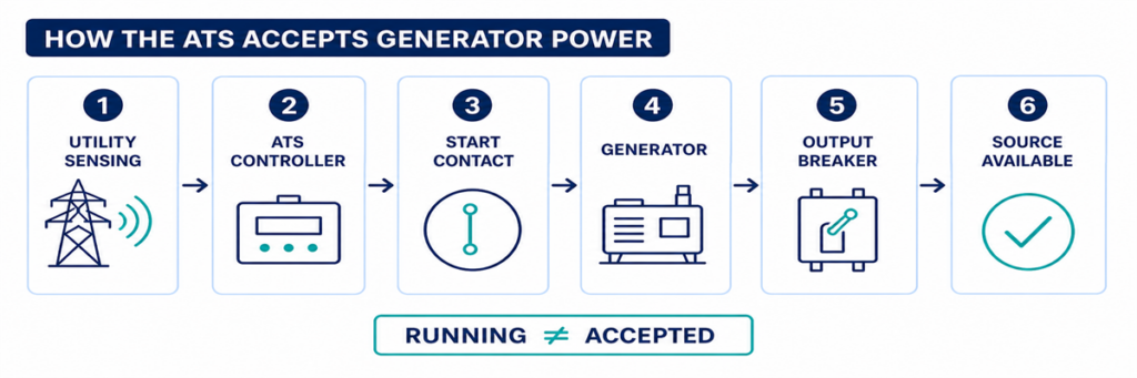
Cách ATS phát hiện và chấp nhận nguồn máy phát trước khi chuyển mạchĐiểm kiểm tra 1: ATS có thực sự từ chối nguồn điện lưới không?
ATS thường vẫn ở vị trí nguồn điện lưới khi bộ điều khiển coi nguồn đó là chấp nhận được. Người vận hành cơ sở có thể thấy đèn mờ, mất điện một phần hoặc sự cố bảng điện phía hạ nguồn trong khi các điểm cảm biến điện áp tại ATS vẫn nằm trong giới hạn đã lập trình. Trong trường hợp đó, việc từ chối chuyển mạch có thể là hành vi đúng chứ không phải lỗi ATS.
Kiểm tra chỉ báo nguồn bình thường và các giá trị của bộ điều khiển cho từng pha được giám sát. So sánh chúng với các chức năng điện áp thấp, điện áp cao, tần số, mất pha và thứ tự pha đã cấu hình cho bộ điều khiển theo đơn đặt hàng. Cũng kiểm tra độ trễ thời gian khi mất nguồn bình thường. Một nhiễu loạn ngắn có thể biến mất trước khi bộ định thời đó hết hạn, cố ý ngăn việc khởi động máy phát không cần thiết.
Common reasons the controller still accepts utility
- The outage is downstream of the ATS sensing point.
- Only a circuit or load feeder has failed.
- The undervoltage pickup/dropout setting does not match the intended operating window.
- A sensing fuse or wiring fault gives the controller an incorrect state.
- The controller is reading the wrong nominal-voltage or source configuration.
- The source-failure delay has not expired.
Do not lower a voltage threshold simply to force transfer. First establish the intended source-quality limits and verify that the sensing configuration matches the system. A loose neutral or missing phase can create hazardous voltages that require investigation, not a wider acceptance window.
Checkpoint 2: Was the Generator Start Command Issued?
When the normal source is rejected, many utility-to-generator ATS controllers operate a dry contact connected to the generator remote-start circuit. The contact may close to start or open to start, depending on the generator and ATS design. The two devices must use compatible logic.
First confirm that the ATS is in AUTO or its normal operating mode. Maintenance, monitor, manual, inhibit, fire-control and exercise modes can intentionally block automatic transfer or change the start sequence. Record active alarms and input states before resetting anything; a reset can erase the most useful evidence.
If the controller shows that the start output has operated but the generator remains stopped, inspect the interface between the ATS and generator. Typical causes include an open control conductor, incorrect use of normally open or normally closed terminals, a loose terminal, a blown control fuse, a disabled generator remote mode, low starting-battery voltage or a generator shutdown alarm.
A jumper should not be improvised across start terminals unless the manufacturer’s procedure explicitly requires it and the test is controlled by qualified personnel. Unexpected generator starting can expose people working on the engine, alternator or downstream circuit.
Checkpoint 3: Is Generator Power Reaching the ATS?
A generator can be running while delivering no usable power to the transfer switch. The engine state and alternate-source electrical state are separate checkpoints.
Look for the controller’s generator-available indication. Check whether the generator output breaker is closed and whether any external isolator, feeder breaker or fuse between the generator and ATS is open. Inspect the generator controller for overvoltage, undervoltage, overspeed, underspeed, excitation, phase or breaker-trip alarms.
Where live testing is authorized, qualified personnel should measure the source at the ATS terminals—not only at the generator display. Confirm the correct phase-to-phase and, where applicable, phase-to-neutral voltages, frequency and phase rotation. A good reading at the alternator but no reading at the ATS points to the intervening breaker, cable, termination or protective device.
Why the ATS may reject a running generator
- Voltage remains outside the programmed acceptance band.
- Frequency has not stabilized.
- One phase is absent or the phase sequence is incorrect.
- The controller nominal voltage or sensing ratio is configured incorrectly.
- The generator breaker is open or has tripped.
- A sensing fuse, transformer or harness is open.
- The generator reaches acceptable conditions only briefly and drops out again.
Do not treat the generator’s unloaded panel voltage as final proof. The relevant value is the source condition recognized by the ATS, and later the voltage and frequency retained when the load is applied.
Trace the Transfer Command, Mechanism and Position Feedback
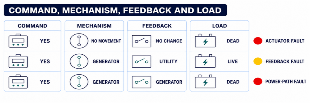
ATS command, switching mechanism, position feedback and load voltage diagnostic comparisonCheckpoint 4: Is a Timer or Permissive Holding the Transfer?
Once the alternate source is acceptable, transfer may still be delayed intentionally. A generator-warm-up timer allows voltage and frequency to stabilize. Other applications require a load-shed confirmation, elevator or motor sequence, UPS status, fire-system input, process permissive, or remote authorization before the switch moves.
Use the controller display to identify which timer is active and whether it is counting. Compare the setting with the approved sequence of operation rather than assuming a delay is excessive. On some controllers a test button or delay-bypass function can shorten a test sequence; this must be used only under the model-specific procedure and when the load is ready to transfer.
If the timer finishes but no command follows, inspect logic inputs for transfer inhibit, emergency inhibit, external trip, source preference, manual retransfer or load-shed confirmation. A permanently energized field contact can make the ATS appear defective while it is obeying the programmed interlock.
Checkpoint 5: Did the Controller Command the Mechanism?
This checkpoint separates a logic problem from an actuator or power-switching problem. Review the event log for commands such as open normal, close alternate, transfer initiated or failure to close. Compare the displayed command with the actual position indicators.
If no command was produced even though source and permissive conditions appear correct, possible causes include an active inhibit, configuration error, failed output, controller power problem or internal controller fault. Verify the controller supply and connectors using the manufacturer’s service instructions before condemning the controller.
If a command was produced, determine whether control voltage reached the relevant motor, solenoid, shunt trip, closing coil or breaker accessory. The exact circuit depends on whether the ATS uses a dedicated switching mechanism, contactors or motorized circuit breakers. Do not apply a generic terminal diagram to a different mechanism.
Checkpoint 6: Can the Switching Mechanism Complete Its Motion?
A controller can issue the correct command while the power mechanism remains in its previous position or stops between positions. Possible causes include:
- missing or low actuator control voltage;
- a blown control fuse or open control transformer secondary;
- a failed motor, solenoid, closing coil or shunt-trip circuit;
- a charged-spring or stored-energy mechanism that is not ready;
- an electrical or mechanical interlock that has not released;
- a breaker that has tripped and requires reset before closing;
- binding, contamination, corrosion or a shipping/maintenance obstruction;
- misaligned or failed limit switches and auxiliary contacts.
Listen for a command and observe the approved external position indication, but do not repeatedly cycle a mechanism that stalls or chatters. Repeated commands can overheat a coil or motor and damage contacts or linkages.
Manual operation is not an ordinary live troubleshooting shortcut. Manufacturer instructions commonly require both utility and generator sources to be isolated before using a manual handle. Follow the exact procedure for the model, verify absence of voltage, and preserve any stored-energy precautions.
Checkpoint 7: Does Position Feedback Agree with the Power Path?
The controller may use auxiliary contacts to prove that one source opened and the other closed. If the mechanism moves but the feedback contact does not change, the controller can report a failed transfer or block the next command. A loose plug, incorrect auxiliary-contact wiring, failed microswitch or mechanical misalignment can create this mismatch.
Compare three independent pieces of evidence:
- the controller’s commanded state;
- the approved mechanical position indicator;
- the electrical state at the load terminals.
These states should agree. If the controller says “load on generator” but the load terminals remain dead, investigate the generator breaker, power contacts, bus connections and downstream protective devices. If load voltage is present but the controller does not confirm position, the feedback circuit is the stronger suspect.
When the ATS Transfers but the Generator Cannot Hold the Load
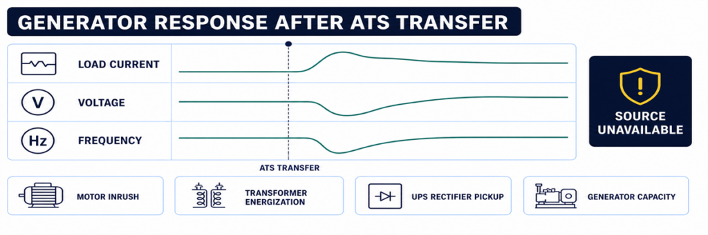
Generator voltage and frequency drop after an automatic transfer switch transfers the loadSome systems complete the movement and then immediately return, trip or lose voltage. That is not the same symptom as “no transfer.” It indicates that the alternate source became unacceptable during or after the load step, or that protection operated.
Review generator voltage, frequency and current trends at the transfer instant. Large motors, transformers, UPS rectifiers and simultaneous load pickup can cause voltage dip or frequency decay. A generator breaker may trip because of overload, short circuit, earth fault or an incorrect protection setting. Phase imbalance or a loose neutral can create a source-quality failure even when total kW appears reasonable.
If the transferred load or generator capacity is uncertain, rebuild the current and load assumptions from the approved load schedule and generator data. The JUTRION generator sizing calculator for ATS backup provides a first-pass check of running load and starting demand. It does not diagnose a control failure, and its result must be verified against the generator manufacturer’s transient-performance data.
Use a Controlled Functional Test to Reproduce the Sequence
A controlled test is more useful than waiting for the next outage. Prepare the load, generator and responsible personnel, then use the test method specified for the ordered ATS. The procedure should verify:
- normal source is initially acceptable and carrying the load;
- the test command initiates the intended engine-start sequence;
- the generator reaches acceptable voltage and frequency;
- the programmed transfer delay operates;
- the mechanism reaches the alternate position;
- the generator carries the intended load without unacceptable voltage or frequency deviation;
- normal-source return and retransfer delay operate;
- the generator completes its cool-down period and stops;
- alarms, event logs, remote indications and position feedback agree throughout.
Do not simulate a failure by disconnecting arbitrary sensing wires or opening energized compartments. Use the controller’s approved test function or the project test procedure. Life-safety, fire-pump, medical, data-centre and continuous-process systems require coordination before any transfer test.
Capture the Evidence Before Resetting or Replacing Parts
Intermittent transfer faults are difficult to diagnose after power has returned and alarms have been cleared. Capture evidence before resetting the system:
- ATS manufacturer, model, controller type and serial number;
- normal and alternate source voltage, frequency and phase configuration;
- controller mode and source-available indicators;
- event and alarm codes with timestamps;
- active delay and its remaining time;
- engine-start output state and generator remote-mode state;
- generator output-breaker position;
- commanded position, mechanical position and feedback state;
- whether the failure occurred unloaded, during transfer or after load pickup;
- recent maintenance, setting changes or wiring work.
This record prevents “controller fault” from becoming the default diagnosis. It also allows a manufacturer or service technician to distinguish an ATS problem from a generator, field-wiring, protection or load problem.
Use the Exact Symptom to Enter the Correct Checkpoint
“The ATS did not transfer” is not specific enough for diagnosis. Record the last state the system completed, then enter the corresponding checkpoint above. This prevents generator, controller and mechanism faults from being mixed together.
| Fault report | First checkpoint | Do not begin by replacing |
|---|---|---|
| Generator did not start | Utility sensing and engine-start output | Power-switching mechanism |
| Generator runs, source unavailable | Generator output at ATS and source settings | ATS main contacts |
| Both sources available, no command | Timers, mode, inhibits and permissives | Generator AVR |
| Command present, no motion | Control power, actuator and interlock | Complete controller without output checks |
| Motion present, wrong status | Auxiliary contacts and position feedback | Generator |
| Transfer followed by collapse | Loaded voltage, frequency, current and protection event | ATS sensing before reviewing the generator event |
| No retransfer to utility | Utility acceptance and return logic | Generator start circuit |
Interpret Controller Indicators Without Treating Them as Measurements
Front-panel indicators are the safest first evidence, but each answers a limited question. A “generator available” LED usually means the controller has accepted the values it senses; it does not prove every phase is present at the load terminals. A “load on generator” indication may be driven by an auxiliary contact; it does not independently measure current flowing to the load.
Use the indicators to form a test hypothesis:
- Normal available: the controller accepts the normal source at its sensing inputs.
- Generator available: alternate-source voltage and frequency have met the configured acceptance logic.
- Engine start active: the controller has commanded its start-output state; field wiring and generator response still require confirmation.
- Transfer timer active: the controller is intentionally waiting, not necessarily stalled.
- Load connected: a position input has changed; verify actual output voltage if the load remains dead.
- Transfer failed: the commanded position was not confirmed within the permitted time.
- Source unavailable: a sensed value is outside acceptance, but the display may not identify whether the cause is the source, sensing circuit or configuration.
If the display provides per-phase voltage and frequency, compare the values with a qualified independent measurement when safe and authorized. A large disagreement points toward sensing wiring, fuses, transformers, selector plugs or configuration. Agreement with an out-of-range value points toward the source itself.
Check Control Power Before Blaming the Controller
A blank screen, intermittent reset or missing output can result from a control-power problem outside the electronic controller. Depending on the ATS design, control power may come from one source, both sources through selection circuitry, a control transformer, a DC supply or an internal power module.
Review the correct schematic and identify which supply should energize the controller at each stage. During a utility failure, an arrangement that normally powers controls from utility must transition to an alternate control source or stored energy. A blown fuse, incorrect transformer tap, loose plug, low DC voltage or failed selector circuit can cause the controller to restart at exactly the time it should transfer.
Evidence of a control-power problem includes:
- display or LEDs resetting when a source fails;
- event-log timestamps restarting;
- relays chattering rather than holding;
- an actuator beginning motion and dropping out;
- normal operation in manual test but failure during a real source interruption;
- different behaviour when the panel door or wiring harness is moved.
Measure control voltage at the condition that produces the fault, not only during stable normal operation. Any live measurement requires appropriate equipment, access boundaries and qualified personnel.
Use Event Timing to Find Intermittent Transfer Failures
An ATS that works during inspection but failed during an outage needs a timeline. Align records from the utility monitor, ATS controller, generator controller, protective devices, BMS or SCADA and critical-load equipment. Even controllers without detailed waveform capture usually preserve enough event order to identify the missing link.
A useful event timeline records:
- the first normal-source abnormality;
- the moment the ATS declared normal unavailable;
- engine-start output operation;
- generator crank and running status;
- alternate-source voltage/frequency available;
- transfer command;
- normal-source open confirmation;
- alternate-source close confirmation;
- load voltage restoration;
- any subsequent trip, retransfer or source-unavailable event.
Timing exposes faults that a static inspection misses. For example, if the generator becomes available for two seconds and then disappears, investigate its stabilization and output. If the transfer command and failed-to-close alarm are separated by the mechanism timeout, investigate actuator power and feedback. If the controller reboots between normal-source loss and engine start, investigate control-power continuity.
Environmental clues matter
Record whether failures coincide with low temperature, high humidity, condensation, dust, vibration, heavy load, battery age or long idle periods. Intermittent connectors, sticky mechanisms, weak starting batteries and enclosure heaters may pass a warm daytime test and fail during an overnight outage. The clue is correlation, not assumption; reproduce the condition safely before replacing parts.
Distinguish an ATS Fault from a Generator or Downstream Fault
The ATS sits between two sources and a load, so symptoms are often assigned to the wrong equipment. Use boundaries at the normal-source terminals, alternate-source terminals and load terminals.
| Evidence | More likely area | Lý do |
|---|---|---|
| No start output from ATS after confirmed source failure | ATS sensing, mode, timer or start logic | The generator has not yet been requested to act |
| Start output changes; generator does not crank | Field wiring, generator remote input, battery or generator alarm | The command left the ATS |
| Generator display shows voltage; ATS alternate terminals do not | Generator breaker, feeder or termination | Power is lost between generator and ATS |
| Alternate voltage reaches ATS; controller reads unavailable | Sensing circuit, settings or controller input | Power exists but is not accepted |
| Alternate source accepted; close command absent | ATS logic, delay, inhibit or permissive | The mechanism has not been asked to move |
| Close command and actuator power present; no movement | Actuator, interlock or mechanism | Logic and control delivery are proven |
| ATS load terminals energized; downstream panel dead | Downstream breaker, cable or load system | The transfer switch has delivered power |
This boundary method also improves communication with suppliers. A report stating “generator voltage was present at ATS alternate terminals, controller remained unavailable, settings and sensing fuses checked” is actionable. “ATS does not work” is not.
Verify Retransfer and Cool-Down as Part of the Same System
A complete automatic sequence does not end when the load reaches generator power. When utility returns, the controller normally verifies that it remains acceptable for a return delay, transfers the load back and keeps the generator running unloaded for a cool-down period before releasing the start command.
If utility has returned but the ATS remains on generator, check normal-source acceptance, return delay, manual-retransfer mode, source preference and external inhibit inputs. In applications where return is intentionally supervised, the system may require an operator command even though automatic transfer to generator was permitted.
If the load returns to utility but the generator continues running, determine whether the ATS start contact remains in the run state, whether the field wiring is shorted, or whether the generator’s own cool-down or exercise logic is active. Avoid changing both ATS and generator timers at once; doing so makes the final cause difficult to prove.
Commission the Complete Sequence and Prevent Repeat Failures
Many transfer failures originate at the interface between equipment supplied by different parties. Commissioning must verify the complete chain, not only that each component powers up.
Confirm the source definitions
Record nominal voltage, frequency, phase sequence, neutral arrangement and source preference. Confirm controller sensing selections or transformer taps against the actual system. Verify that both sources and the ATS are compatible before attempting transfer.
Prove the engine-start interface
Document whether the generator expects close-to-start or open-to-start logic and which terminals are used at both ends. Confirm remote mode, conductor continuity and the response to an approved ATS test command.
Prove every timer and inhibit
Record source-failure delay, engine-start delay, generator stabilization, transfer, return and cool-down settings. Operate external inhibit, load-shed and permissive contacts one at a time and verify that controller indication matches the intended sequence.
Prove position and remote status
Verify normal connected, alternate connected, source available, common alarm and transfer-failure outputs at the local display and remote monitoring system. Incorrectly mapped feedback can make a healthy ATS look failed to the BMS—or conceal a real failure.
Test under a representative load
A no-load movement test proves mechanics and part of the control chain, but it does not prove generator response to load pickup or contact-path performance. Where the project procedure permits, perform a representative loaded transfer and record voltage, frequency and current. Stage loads when the approved operating sequence requires it.
Leave a baseline record
Save settings, timer values, event logs, source readings, transfer times and position-feedback states from a successful test. Future technicians can compare a failed event against this known-good sequence rather than relying on memory.
Prevent the Same No-Transfer Fault from Returning
Exercise the complete system at an interval appropriate to the application and local requirements, not only the generator engine. A no-load engine run does not prove that the ATS senses, transfers, carries load, retransfers and stops correctly.
Maintenance should include inspection of control wiring, terminals, fuses, connectors, enclosure condition, heaters where fitted, position indication, mechanical operation under an approved isolated procedure, event logs and generator batteries. Review controller settings after firmware, generator, transformer, protection or load changes.
For projects selecting replacement equipment, confirm source arrangement, voltage, frequency, current, poles and neutral treatment, transfer class, short-circuit coordination, controller I/O and enclosure conditions. Use the JUTRION automatic transfer switch sizing calculator to screen load current, a suitable rating step and the initial pole/configuration questions. It cannot select the final ATS without the fault-current, neutral, transition and controller checks.
After those project inputs are confirmed, compare the result with the JUTRION automatic transfer switch range. The available PC-class, CB-class and controller configurations still have to be matched to the actual source, protection and operating sequence.
Câu hỏi Thường gặp
Why does the generator start but the ATS not transfer?
The ATS may not see acceptable generator voltage or frequency, the generator breaker may be open, a stabilization delay or inhibit may be active, or the controller may command transfer while the mechanism or feedback circuit fails. Identify the first missing state in the transfer sequence.
Can I manually move an ATS to generator power?
Only under the model-specific manufacturer procedure. Many transfer switches require both sources to be disconnected before manual operation. Never use the manual handle as a live troubleshooting shortcut.
Why does the ATS transfer and then immediately return?
The generator source may fall outside its voltage or frequency acceptance window when load is applied, or the generator breaker/protection may operate. Check the event log and generator behaviour during the load step.
Can an incorrect time-delay setting stop an ATS from transferring?
Yes. Source-failure, engine-start, generator-stabilization and transfer delays can make a correct sequence appear stalled. An active inhibit or permissive can also block transfer after the timer ends.
Does a blank ATS controller mean the complete switch has failed?
Not necessarily. Missing controller power, an open control fuse, transformer or harness problem can blank the display. Verify the control-power path under the manufacturer’s service procedure before replacing the controller.
Finish the Diagnosis at the First Missing State
Do not begin with the most expensive component. Begin with the sequence. If the ATS never rejects utility, investigate sensing and settings. If it rejects utility but never requests a start, investigate mode, timers and the start circuit. If the generator runs but remains unavailable, investigate its electrical output and the ATS sensing path. If the source is accepted but the switch does not move, investigate permissives, control power, actuator and interlocks. If the mechanism moves but the load remains dead, verify the power path and feedback.
That evidence-led order shortens downtime and avoids replacing a controller for a generator breaker, a mechanism for an active inhibit, or an entire ATS for one open control conductor.
