

Quick Answer: Why Is the Automatic Transfer Switch Not Switching to the Generator?
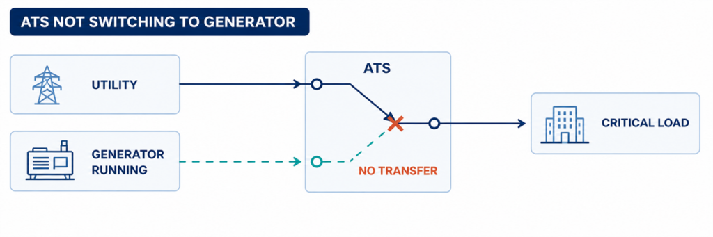
Automatic transfer switch not switching to the generator while the generator is runningIf an automatic transfer switch is not switching to generator power, find the first failed step in the transfer sequence. Confirm whether the ATS detected an unacceptable utility source, issued the engine-start command, received acceptable generator voltage and frequency, completed its programmed delay, operated the switching mechanism, and returned the correct position feedback. The first missing state normally identifies the fault area.
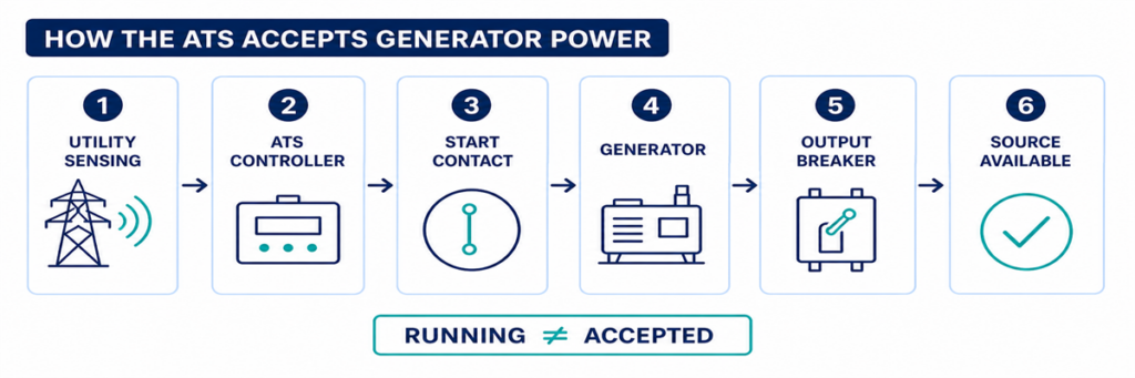
A running generator does not prove that the ATS is ready to transfer. The generator output breaker may be open, voltage or frequency may remain outside the controller acceptance window, a phase may be missing, a permissive input may be absent, or the mechanism may fail after the controller issues the command. Troubleshooting becomes faster when these conditions are checked in sequence instead of replacing the controller first.
Safety boundary: an ATS enclosure can contain live utility and generator conductors at the same time. Operators may record indicators, alarms and controller events without opening energized compartments. Voltage measurements, continuity tests, manual mechanism operation and internal inspection must follow the ordered equipment manual, site switching procedure and applicable electrical-safety rules, and should be performed only by qualified personnel.
Read the Failure as a Broken Transfer Sequence
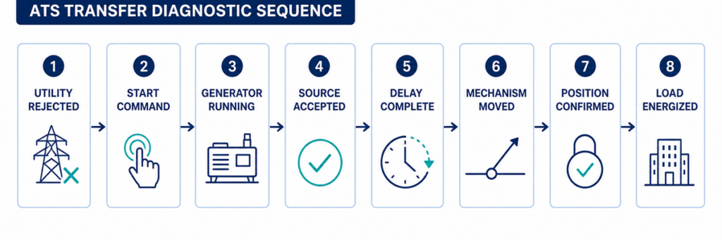
ATS diagnostic sequence from utility failure to generator load transferAn automatic transfer is a chain of decisions rather than one movement. A typical utility-to-generator sequence is:
- The controller monitors the normal source.
- The normal source becomes unacceptable for longer than the programmed detection delay.
- The ATS changes its engine-start contact to command the generator.
- The generator starts and develops voltage and frequency at the ATS alternate-source terminals.
- The controller accepts the alternate source after its stabilization delay.
- Interlocks and permissives allow a transfer command.
- The mechanism disconnects the normal source and connects the alternate source according to its transition design.
- Auxiliary contacts confirm the new position.
- Voltage appears at the load terminals and the generator carries the transferred load.
Start with the controller event log and front-panel source/position indicators. Write down the last confirmed step. If the generator never receives a start request, inspecting power contacts will not solve the problem. If the controller shows the generator as available but the mechanism never moves, changing generator settings will not solve it either.
Record These Parameters Before Changing a Setting
The useful parameters are the values that determine whether the controller accepts a source and permits movement. Record the current settings and observed values before making any change. Acceptance windows and delay ranges are controller- and project-specific; the table identifies what to capture, not universal setpoints.
| Parameter | What to record | Why it matters | Evidence source |
|---|---|---|---|
| Nominal source voltage | Configured nominal value and system phase arrangement | Wrong configuration can make a healthy source appear unacceptable | Approved settings file, nameplate and one-line diagram |
| Undervoltage and overvoltage limits | Pickup/dropout values or percentage settings for each source | The ATS transfers only after source voltage crosses the applicable limit and delay | Controller menu and sequence of operation |
| Frequency limits | Underfrequency/overfrequency acceptance values | A running generator may still be rejected while speed is unstable | Controller menu and generator data |
| Phase monitoring | Phase loss, phase sequence and phase-unbalance functions enabled | One incorrect phase condition can block source acceptance | Controller status and settings |
| Source-failure delay | Time from unacceptable utility to engine-start action | Prevents starting for a brief disturbance | Active-timer display and approved settings |
| Generator stabilization delay | Time after the alternate source becomes acceptable before transfer | Allows voltage and frequency to settle | Controller timer and event log |
| Transfer and mechanism timeout | Permitted time for open/close command and position confirmation | A timeout separates slow or failed motion from normal delay | Alarm code, event log and controller manual |
| Retransfer and cool-down delays | Utility-return verification time and unloaded generator run time | Explains why the ATS remains on generator or why the engine continues running | Controller and generator settings |
| Engine-start contact logic | Close-to-start or open-to-start; terminal numbers and observed state | Incompatible logic prevents the generator receiving the intended command | ATS schematic and generator remote-start diagram |
| Control supply | Rated AC/DC control voltage and value during the failed event | A control-voltage dip can reset the controller or drop the actuator | Ordered schematic and qualified measurement |
| Permissive and inhibit inputs | Normal state and state during the failed transfer | An external contact may intentionally block movement | I/O status screen, PLC/BMS log and wiring diagram |
| Position feedback | Normal-open, alternate-closed and intermediate-position contact states | The controller may command correctly but fail to confirm movement | Controller I/O screen and auxiliary-contact diagram |
| Observed state | Likely fault area | Best next evidence |
|---|---|---|
| Utility failed; generator does not start | ATS mode, sensing, start delay, start contact or control wiring | Normal-source status, active timer, start-output indication and generator remote-mode status |
| Generator runs; ATS says source unavailable | Generator output, breaker, voltage/frequency, phase or sensing circuit | Generator-available indicator, controller readings and qualified measurement at source terminals |
| Generator is available; no transfer command | Delay, inhibit, permissive, test mode or control logic | Active timer, inhibit input, alarm and event log |
| Transfer command appears; mechanism does not move | Control supply, actuator, coil, motor, interlock or mechanical obstruction | Command output, actuator supply and position feedback |
| Mechanism moves; load remains dead | Open generator breaker, damaged contact path, output connection or downstream protection | ATS position, source and load voltage, breaker states |
| Transfer occurs; generator trips or voltage collapses | Load step, generator capacity, inrush, protection setting or phase problem | Generator event log, current, frequency and voltage during the transfer |
Confirm Source Recognition from Utility Failure to Generator Availability
How an ATS detects and accepts generator power before transferringCheckpoint 1: Did the ATS Actually Reject the Utility Source?
The ATS normally remains on utility while the controller considers that source acceptable. A facility operator may see dim lights, a partial outage or a downstream panel failure while the voltage-sensing points at the ATS remain within their programmed limits. In that case, refusing to transfer may be correct behaviour rather than an ATS fault.
Check the normal-source indicator and the controller values for each monitored phase. Compare them with the configured undervoltage, overvoltage, frequency, phase-loss and phase-sequence functions for the ordered controller. Also check the time delay on normal-source failure. A short disturbance may disappear before that timer expires, deliberately preventing an unnecessary generator start.
Common reasons the controller still accepts utility
- The outage is downstream of the ATS sensing point.
- Only a circuit or load feeder has failed.
- The undervoltage pickup/dropout setting does not match the intended operating window.
- A sensing fuse or wiring fault gives the controller an incorrect state.
- The controller is reading the wrong nominal-voltage or source configuration.
- The source-failure delay has not expired.
Do not lower a voltage threshold simply to force transfer. First establish the intended source-quality limits and verify that the sensing configuration matches the system. A loose neutral or missing phase can create hazardous voltages that require investigation, not a wider acceptance window.
Checkpoint 2: Was the Generator Start Command Issued?
When the normal source is rejected, many utility-to-generator ATS controllers operate a dry contact connected to the generator remote-start circuit. The contact may close to start or open to start, depending on the generator and ATS design. The two devices must use compatible logic.
First confirm that the ATS is in AUTO or its normal operating mode. Maintenance, monitor, manual, inhibit, fire-control and exercise modes can intentionally block automatic transfer or change the start sequence. Record active alarms and input states before resetting anything; a reset can erase the most useful evidence.
If the controller shows that the start output has operated but the generator remains stopped, inspect the interface between the ATS and generator. Typical causes include an open control conductor, incorrect use of normally open or normally closed terminals, a loose terminal, a blown control fuse, a disabled generator remote mode, low starting-battery voltage or a generator shutdown alarm.
A jumper should not be improvised across start terminals unless the manufacturer’s procedure explicitly requires it and the test is controlled by qualified personnel. Unexpected generator starting can expose people working on the engine, alternator or downstream circuit.
Checkpoint 3: Is Generator Power Reaching the ATS?
A generator can be running while delivering no usable power to the transfer switch. The engine state and alternate-source electrical state are separate checkpoints.
Look for the controller’s generator-available indication. Check whether the generator output breaker is closed and whether any external isolator, feeder breaker or fuse between the generator and ATS is open. Inspect the generator controller for overvoltage, undervoltage, overspeed, underspeed, excitation, phase or breaker-trip alarms.
Where live testing is authorized, qualified personnel should measure the source at the ATS terminals—not only at the generator display. Confirm the correct phase-to-phase and, where applicable, phase-to-neutral voltages, frequency and phase rotation. A good reading at the alternator but no reading at the ATS points to the intervening breaker, cable, termination or protective device.
Why the ATS may reject a running generator
- Voltage remains outside the programmed acceptance band.
- Frequency has not stabilized.
- One phase is absent or the phase sequence is incorrect.
- The controller nominal voltage or sensing ratio is configured incorrectly.
- The generator breaker is open or has tripped.
- A sensing fuse, transformer or harness is open.
- The generator reaches acceptable conditions only briefly and drops out again.
Do not treat the generator’s unloaded panel voltage as final proof. The relevant value is the source condition recognized by the ATS, and later the voltage and frequency retained when the load is applied.
Trace the Transfer Command, Mechanism and Position Feedback
ATS command, switching mechanism, position feedback and load voltage diagnostic comparisonCheckpoint 4: Is a Timer or Permissive Holding the Transfer?
Once the alternate source is acceptable, transfer may still be delayed intentionally. A generator-warm-up timer allows voltage and frequency to stabilize. Other applications require a load-shed confirmation, elevator or motor sequence, UPS status, fire-system input, process permissive, or remote authorization before the switch moves.
Use the controller display to identify which timer is active and whether it is counting. Compare the setting with the approved sequence of operation rather than assuming a delay is excessive. On some controllers a test button or delay-bypass function can shorten a test sequence; this must be used only under the model-specific procedure and when the load is ready to transfer.
If the timer finishes but no command follows, inspect logic inputs for transfer inhibit, emergency inhibit, external trip, source preference, manual retransfer or load-shed confirmation. A permanently energized field contact can make the ATS appear defective while it is obeying the programmed interlock.
Checkpoint 5: Did the Controller Command the Mechanism?
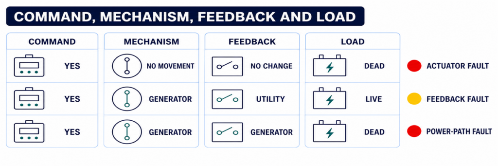
This checkpoint separates a logic problem from an actuator or power-switching problem. Review the event log for commands such as open normal, close alternate, transfer initiated or failure to close. Compare the displayed command with the actual position indicators.
If no command was produced even though source and permissive conditions appear correct, possible causes include an active inhibit, configuration error, failed output, controller power problem or internal controller fault. Verify the controller supply and connectors using the manufacturer’s service instructions before condemning the controller.
If a command was produced, determine whether control voltage reached the relevant motor, solenoid, shunt trip, closing coil or breaker accessory. The exact circuit depends on whether the ATS uses a dedicated switching mechanism, contactors or motorized circuit breakers. Do not apply a generic terminal diagram to a different mechanism.
Checkpoint 6: Can the Switching Mechanism Complete Its Motion?
A controller can issue the correct command while the power mechanism remains in its previous position or stops between positions. Possible causes include:
- missing or low actuator control voltage;
- a blown control fuse or open control transformer secondary;
- a failed motor, solenoid, closing coil or shunt-trip circuit;
- a charged-spring or stored-energy mechanism that is not ready;
- an electrical or mechanical interlock that has not released;
- a breaker that has tripped and requires reset before closing;
- binding, contamination, corrosion or a shipping/maintenance obstruction;
- misaligned or failed limit switches and auxiliary contacts.
Listen for a command and observe the approved external position indication, but do not repeatedly cycle a mechanism that stalls or chatters. Repeated commands can overheat a coil or motor and damage contacts or linkages.
Manual operation is not an ordinary live troubleshooting shortcut. Manufacturer instructions commonly require both utility and generator sources to be isolated before using a manual handle. Follow the exact procedure for the model, verify absence of voltage, and preserve any stored-energy precautions.
Checkpoint 7: Does Position Feedback Agree with the Power Path?
The controller may use auxiliary contacts to prove that one source opened and the other closed. If the mechanism moves but the feedback contact does not change, the controller can report a failed transfer or block the next command. A loose plug, incorrect auxiliary-contact wiring, failed microswitch or mechanical misalignment can create this mismatch.
Compare three independent pieces of evidence:
- the controller’s commanded state;
- the approved mechanical position indicator;
- the electrical state at the load terminals.
These states should agree. If the controller says “load on generator” but the load terminals remain dead, investigate the generator breaker, power contacts, bus connections and downstream protective devices. If load voltage is present but the controller does not confirm position, the feedback circuit is the stronger suspect.
When the ATS Transfers but the Generator Cannot Hold the Load
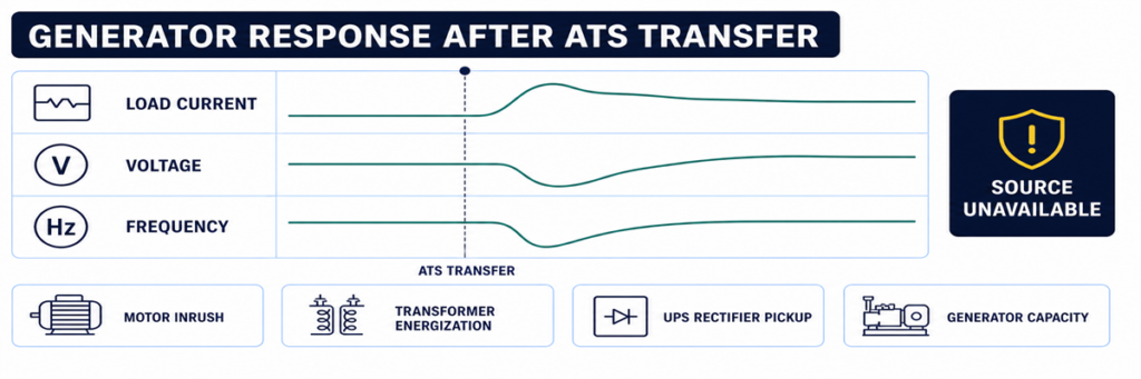
Generator voltage and frequency drop after an automatic transfer switch transfers the loadSome systems complete the movement and then immediately return, trip or lose voltage. That is not the same symptom as “no transfer.” It indicates that the alternate source became unacceptable during or after the load step, or that protection operated.
Review generator voltage, frequency and current trends at the transfer instant. Large motors, transformers, UPS rectifiers and simultaneous load pickup can cause voltage dip or frequency decay. A generator breaker may trip because of overload, short circuit, earth fault or an incorrect protection setting. Phase imbalance or a loose neutral can create a source-quality failure even when total kW appears reasonable.
If the transferred load or generator capacity is uncertain, rebuild the current and load assumptions from the approved load schedule and generator data. The JUTRION generator sizing calculator for ATS backup provides a first-pass check of running load and starting demand. It does not diagnose a control failure, and its result must be verified against the generator manufacturer’s transient-performance data.
Use a Controlled Functional Test to Reproduce the Sequence
A controlled test is more useful than waiting for the next outage. Prepare the load, generator and responsible personnel, then use the test method specified for the ordered ATS. The procedure should verify:
- normal source is initially acceptable and carrying the load;
- the test command initiates the intended engine-start sequence;
- the generator reaches acceptable voltage and frequency;
- the programmed transfer delay operates;
- the mechanism reaches the alternate position;
- the generator carries the intended load without unacceptable voltage or frequency deviation;
- normal-source return and retransfer delay operate;
- the generator completes its cool-down period and stops;
- alarms, event logs, remote indications and position feedback agree throughout.
Do not simulate a failure by disconnecting arbitrary sensing wires or opening energized compartments. Use the controller’s approved test function or the project test procedure. Life-safety, fire-pump, medical, data-centre and continuous-process systems require coordination before any transfer test.
Capture the Evidence Before Resetting or Replacing Parts
Intermittent transfer faults are difficult to diagnose after power has returned and alarms have been cleared. Capture evidence before resetting the system:
- ATS manufacturer, model, controller type and serial number;
- normal and alternate source voltage, frequency and phase configuration;
- controller mode and source-available indicators;
- event and alarm codes with timestamps;
- active delay and its remaining time;
- engine-start output state and generator remote-mode state;
- generator output-breaker position;
- commanded position, mechanical position and feedback state;
- whether the failure occurred unloaded, during transfer or after load pickup;
- recent maintenance, setting changes or wiring work.
This record prevents “controller fault” from becoming the default diagnosis. It also allows a manufacturer or service technician to distinguish an ATS problem from a generator, field-wiring, protection or load problem.
Use the Exact Symptom to Enter the Correct Checkpoint
“The ATS did not transfer” is not specific enough for diagnosis. Record the last state the system completed, then enter the corresponding checkpoint above. This prevents generator, controller and mechanism faults from being mixed together.
| Fault report | First checkpoint | Do not begin by replacing |
|---|---|---|
| Generator did not start | Utility sensing and engine-start output | Power-switching mechanism |
| Generator runs, source unavailable | Generator output at ATS and source settings | ATS main contacts |
| Both sources available, no command | Timers, mode, inhibits and permissives | Generator AVR |
| Command present, no motion | Control power, actuator and interlock | Complete controller without output checks |
| Motion present, wrong status | Auxiliary contacts and position feedback | Generator |
| Transfer followed by collapse | Loaded voltage, frequency, current and protection event | ATS sensing before reviewing the generator event |
| No retransfer to utility | Utility acceptance and return logic | Generator start circuit |
Interpret Controller Indicators Without Treating Them as Measurements
Front-panel indicators are the safest first evidence, but each answers a limited question. A “generator available” LED usually means the controller has accepted the values it senses; it does not prove every phase is present at the load terminals. A “load on generator” indication may be driven by an auxiliary contact; it does not independently measure current flowing to the load.
Use the indicators to form a test hypothesis:
- Normal available: the controller accepts the normal source at its sensing inputs.
- Generator available: alternate-source voltage and frequency have met the configured acceptance logic.
- Engine start active: the controller has commanded its start-output state; field wiring and generator response still require confirmation.
- Transfer timer active: the controller is intentionally waiting, not necessarily stalled.
- Load connected: a position input has changed; verify actual output voltage if the load remains dead.
- Transfer failed: the commanded position was not confirmed within the permitted time.
- Source unavailable: a sensed value is outside acceptance, but the display may not identify whether the cause is the source, sensing circuit or configuration.
If the display provides per-phase voltage and frequency, compare the values with a qualified independent measurement when safe and authorized. A large disagreement points toward sensing wiring, fuses, transformers, selector plugs or configuration. Agreement with an out-of-range value points toward the source itself.
Check Control Power Before Blaming the Controller
A blank screen, intermittent reset or missing output can result from a control-power problem outside the electronic controller. Depending on the ATS design, control power may come from one source, both sources through selection circuitry, a control transformer, a DC supply or an internal power module.
Review the correct schematic and identify which supply should energize the controller at each stage. During a utility failure, an arrangement that normally powers controls from utility must transition to an alternate control source or stored energy. A blown fuse, incorrect transformer tap, loose plug, low DC voltage or failed selector circuit can cause the controller to restart at exactly the time it should transfer.
Evidence of a control-power problem includes:
- display or LEDs resetting when a source fails;
- event-log timestamps restarting;
- relays chattering rather than holding;
- an actuator beginning motion and dropping out;
- normal operation in manual test but failure during a real source interruption;
- different behaviour when the panel door or wiring harness is moved.
Measure control voltage at the condition that produces the fault, not only during stable normal operation. Any live measurement requires appropriate equipment, access boundaries and qualified personnel.
Use Event Timing to Find Intermittent Transfer Failures
An ATS that works during inspection but failed during an outage needs a timeline. Align records from the utility monitor, ATS controller, generator controller, protective devices, BMS or SCADA and critical-load equipment. Even controllers without detailed waveform capture usually preserve enough event order to identify the missing link.
A useful event timeline records:
- the first normal-source abnormality;
- the moment the ATS declared normal unavailable;
- engine-start output operation;
- generator crank and running status;
- alternate-source voltage/frequency available;
- transfer command;
- normal-source open confirmation;
- alternate-source close confirmation;
- load voltage restoration;
- any subsequent trip, retransfer or source-unavailable event.
Timing exposes faults that a static inspection misses. For example, if the generator becomes available for two seconds and then disappears, investigate its stabilization and output. If the transfer command and failed-to-close alarm are separated by the mechanism timeout, investigate actuator power and feedback. If the controller reboots between normal-source loss and engine start, investigate control-power continuity.
Environmental clues matter
Record whether failures coincide with low temperature, high humidity, condensation, dust, vibration, heavy load, battery age or long idle periods. Intermittent connectors, sticky mechanisms, weak starting batteries and enclosure heaters may pass a warm daytime test and fail during an overnight outage. The clue is correlation, not assumption; reproduce the condition safely before replacing parts.
Distinguish an ATS Fault from a Generator or Downstream Fault
The ATS sits between two sources and a load, so symptoms are often assigned to the wrong equipment. Use boundaries at the normal-source terminals, alternate-source terminals and load terminals.
| Evidence | More likely area | Reason |
|---|---|---|
| No start output from ATS after confirmed source failure | ATS sensing, mode, timer or start logic | The generator has not yet been requested to act |
| Start output changes; generator does not crank | Field wiring, generator remote input, battery or generator alarm | The command left the ATS |
| Generator display shows voltage; ATS alternate terminals do not | Generator breaker, feeder or termination | Power is lost between generator and ATS |
| Alternate voltage reaches ATS; controller reads unavailable | Sensing circuit, settings or controller input | Power exists but is not accepted |
| Alternate source accepted; close command absent | ATS logic, delay, inhibit or permissive | The mechanism has not been asked to move |
| Close command and actuator power present; no movement | Actuator, interlock or mechanism | Logic and control delivery are proven |
| ATS load terminals energized; downstream panel dead | Downstream breaker, cable or load system | The transfer switch has delivered power |
This boundary method also improves communication with suppliers. A report stating “generator voltage was present at ATS alternate terminals, controller remained unavailable, settings and sensing fuses checked” is actionable. “ATS does not work” is not.
Verify Retransfer and Cool-Down as Part of the Same System
A complete automatic sequence does not end when the load reaches generator power. When utility returns, the controller normally verifies that it remains acceptable for a return delay, transfers the load back and keeps the generator running unloaded for a cool-down period before releasing the start command.
If utility has returned but the ATS remains on generator, check normal-source acceptance, return delay, manual-retransfer mode, source preference and external inhibit inputs. In applications where return is intentionally supervised, the system may require an operator command even though automatic transfer to generator was permitted.
If the load returns to utility but the generator continues running, determine whether the ATS start contact remains in the run state, whether the field wiring is shorted, or whether the generator’s own cool-down or exercise logic is active. Avoid changing both ATS and generator timers at once; doing so makes the final cause difficult to prove.
Commission the Complete Sequence and Prevent Repeat Failures
Many transfer failures originate at the interface between equipment supplied by different parties. Commissioning must verify the complete chain, not only that each component powers up.
Confirm the source definitions
Record nominal voltage, frequency, phase sequence, neutral arrangement and source preference. Confirm controller sensing selections or transformer taps against the actual system. Verify that both sources and the ATS are compatible before attempting transfer.
Prove the engine-start interface
Document whether the generator expects close-to-start or open-to-start logic and which terminals are used at both ends. Confirm remote mode, conductor continuity and the response to an approved ATS test command.
Prove every timer and inhibit
Record source-failure delay, engine-start delay, generator stabilization, transfer, return and cool-down settings. Operate external inhibit, load-shed and permissive contacts one at a time and verify that controller indication matches the intended sequence.
Prove position and remote status
Verify normal connected, alternate connected, source available, common alarm and transfer-failure outputs at the local display and remote monitoring system. Incorrectly mapped feedback can make a healthy ATS look failed to the BMS—or conceal a real failure.
Test under a representative load
Uji gerakan tanpa beban membuktikan mekanik dan sebagian rantai kendali, tetapi tidak membuktikan respons generator terhadap pengambilan beban atau kinerja jalur kontak. Jika prosedur proyek mengizinkan, lakukan transfer berbeban yang representatif dan catat tegangan, frekuensi, serta arus. Atur beban bertahap bila urutan operasi yang disetujui mensyaratkannya.
Tinggalkan catatan dasar
Simpan pengaturan, nilai pewaktu, log kejadian, pembacaan sumber, waktu transfer, dan status umpan balik posisi dari pengujian yang berhasil. Teknisi di masa mendatang dapat membandingkan kejadian gagal dengan urutan yang diketahui baik ini alih-alih mengandalkan ingatan.
Cegah Gangguan Tanpa Transfer yang Sama agar Tidak Kembali
Latih sistem lengkap pada interval yang sesuai dengan aplikasi dan persyaratan setempat, bukan hanya mesin generator. Pengoperasian mesin tanpa beban tidak membuktikan bahwa ATS mendeteksi, mentransfer, memikul beban, mentransfer balik, dan berhenti dengan benar.
Pemeliharaan harus mencakup pemeriksaan kabel kendali, terminal, sekring, konektor, kondisi selungkup, pemanas jika terpasang, indikasi posisi, operasi mekanis di bawah prosedur terisolasi yang disetujui, log kejadian, dan baterai generator. Tinjau pengaturan pengendali setelah perubahan firmware, generator, transformator, proteksi, atau beban.
Untuk proyek yang memilih peralatan pengganti, konfirmasikan susunan sumber, tegangan, frekuensi, arus, kutub dan perlakuan netral, kelas transfer, koordinasi hubung singkat, I/O pengendali, dan kondisi selungkup. Gunakan JUTRION kalkulator ukuran sakelar transfer otomatis untuk menyaring arus beban, langkah peringkat yang sesuai, dan pertanyaan awal kutub/konfigurasi. Kalkulator ini tidak dapat memilih ATS akhir tanpa pemeriksaan arus gangguan, netral, transisi, dan pengendali.
Setelah masukan proyek tersebut dikonfirmasi, bandingkan hasilnya dengan rangkaian sakelar transfer otomatis JUTRION. Konfigurasi kelas PC, kelas CB, dan pengendali yang tersedia tetap harus disesuaikan dengan sumber, proteksi, dan urutan operasi aktual.
Pertanyaan yang Sering Diajukan
Mengapa generator menyala tetapi ATS tidak mentransfer?
ATS mungkin tidak melihat tegangan atau frekuensi generator yang dapat diterima, pemutus generator mungkin terbuka, tunda stabilisasi atau inhibisi mungkin aktif, atau pengendali mungkin memerintahkan transfer sementara mekanisme atau rangkaian umpan balik gagal. Identifikasi keadaan hilang pertama dalam urutan transfer.
Dapatkah saya menggerakkan ATS secara manual ke daya generator?
Hanya berdasarkan prosedur pabrikan khusus model. Banyak sakelar transfer mensyaratkan kedua sumber diputus sebelum operasi manual. Jangan pernah menggunakan tuas manual sebagai jalan pintas pemecahan masalah dalam kondisi bertegangan.
Mengapa ATS mentransfer lalu segera kembali?
Sumber generator mungkin berada di luar jendela penerimaan tegangan atau frekuensinya saat beban diterapkan, atau pemutus/proteksi generator mungkin bekerja. Periksa log kejadian dan perilaku generator selama langkah beban.
Dapatkah pengaturan tunda waktu yang salah menghentikan ATS dari transfer?
Ya. Tunda kegagalan sumber, nyala mesin, stabilisasi generator, dan transfer dapat membuat urutan yang benar tampak terhenti. Inhibisi atau permissif yang aktif juga dapat memblokir transfer setelah pewaktu berakhir.
Apakah pengendali ATS yang kosong berarti sakelar lengkap telah gagal?
Belum tentu. Daya pengendali yang hilang, sekring kendali yang terbuka, masalah transformator atau harness dapat mengosongkan layar. Verifikasi jalur daya kendali berdasarkan prosedur servis pabrikan sebelum mengganti pengendali.
Selesaikan Diagnosis pada Keadaan Hilang Pertama
Jangan mulai dengan komponen yang paling mahal. Mulailah dengan urutannya. Jika ATS tidak pernah menolak utilitas, periksa penginderaan dan pengaturannya. Jika ATS menolak utilitas tetapi tidak pernah meminta start, periksa mode, timer, dan sirkuit start. Jika generator berjalan tetapi tetap tidak tersedia, periksa keluaran listriknya dan jalur penginderaan ATS. Jika sumber diterima tetapi sakelar tidak bergerak, periksa permissives, daya kontrol, aktuator, dan interlock. Jika mekanisme bergerak tetapi beban tetap mati, verifikasi jalur daya dan umpan balik.
Urutan berbasis bukti tersebut mempersingkat waktu henti dan menghindari penggantian pengontrol karena pemutus generator, mekanisme karena inhibit aktif, atau seluruh ATS karena satu konduktor kontrol yang terbuka.
