

คู่มือการควบคุม การเลือก และการติดตั้งใหม่ของกลไกการทำงานด้วยมอเตอร์สำหรับ MCCB
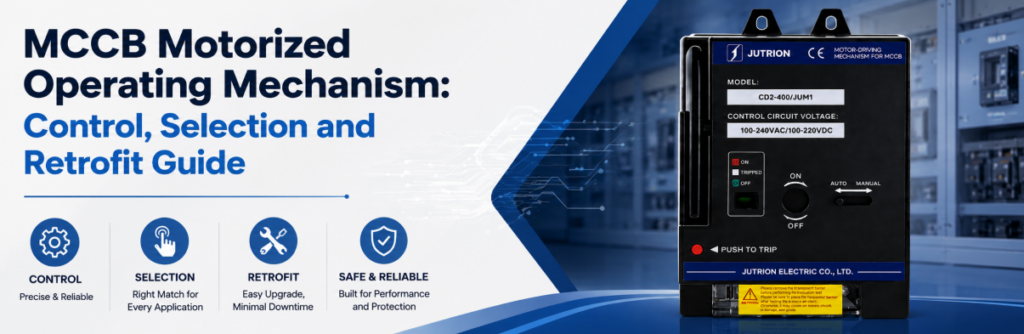
คู่มือการควบคุม การเลือก และการติดตั้งเพิ่มเติมกลไกการทำงานแบบมอเตอร์ของ MCCBคำตอบโดยย่อ: กลไกมอเตอร์ของ MCCB ทำหน้าที่อะไร?
An กลไกการทำงานแบบมอเตอร์ของ MCCB, หรือที่เรียกว่ากลไกมอเตอร์ของ MCCB คือตัวกระตุ้นทางไฟฟ้าที่เคลื่อนเบรกเกอร์ชนิดโมลด์เคสที่เข้ากันได้ระหว่างสถานะทางกลตามคำสั่ง ขึ้นอยู่กับเบรกเกอร์และกลไกที่จับคู่กัน มันสามารถเปิด ปิด และรีเซ็ตเบรกเกอร์หลังจากการทริปได้ เป็นอุปกรณ์เสริมของเบรกเกอร์เพียงชนิดเดียวที่สามารถ ปิด เบรกเกอร์จากระยะไกลได้ — ชันต์ทริปและอันเดอร์โวลเทจรีลีสสามารถเปิดได้อย่างเดียวเท่านั้น.
ห้องควบคุมส่งคำสั่ง CLOSE ไปยังเบรกเกอร์ป้อนไฟแล้วไม่มีอะไรเกิดขึ้น ข้อสันนิษฐานแรกตามปกติคือมอเตอร์เสีย แต่มอเตอร์มักจะยังดีอยู่: เบรกเกอร์อาจยังอยู่ในสถานะ TRIPPED ตัวเลือกอาจอยู่ที่ MANUAL สัญญาณอนุญาตให้ปิดอาจขาดหายไป หรือแหล่งจ่ายควบคุมอาจแรงดันตกในระหว่างการทำงาน.
นั่นคือประเด็นหลักของคู่มือนี้ กลไกมอเตอร์ไม่ใช่มือไฟฟ้าที่หมุนคันโยก แต่มันคือข้อต่อหนึ่งในโซ่: ระบบอัตโนมัติออกคำสั่ง ลอจิกอนุญาตตัดสินว่าอนุญาตหรือไม่ กลไกเคลื่อนเบรกเกอร์ และหน้าสัมผัสเสริมยืนยันผลลัพธ์ หากข้อต่อใดไม่ถูกระบุไว้ “การทำงานระยะไกลของ MCCB” ก็ไม่ใช่ฟังก์ชันที่สมบูรณ์.
กลไกมอเตอร์ก็ไม่ใช่อุปกรณ์ป้องกันเช่นกัน มันไม่ตรวจจับกระแส ไม่ทริปเมื่อเกิดฟอลต์ และไม่เพิ่มค่า Iลูกบาศก์ หรือเปลี่ยนทริปยูนิตของเบรกเกอร์ และมันก็ไม่ใช่สิ่งทดแทนคอนแทกเตอร์: เบรกเกอร์ที่มีกลไกมอเตอร์ถูกสร้างมาเพื่อการทำงานที่ไม่บ่อยครั้ง ไม่ใช่สำหรับรอบการทำงานนับพันครั้งต่อวันที่วงจรมอเตอร์ต้องการ.
ใช้คู่มือนี้ในสามรอบ:
- ยืนยันว่าโครงการต้องการเพียงการเปิดจากระยะไกล หรือต้องการการรีเซ็ตและการปิดจากระยะไกลด้วย.
- ตรวจสอบความเข้ากันได้ทางกล แรงดันควบคุม ความต้องการกระแสเริ่มต้น และแรงดันตกในสายเคเบิล.
- กำหนดสัญญาณอนุญาต การป้อนกลับ อินเทอร์ล็อก และพฤติกรรมหลังการทริปป้องกัน.
ข้อมูลจำเพาะโดยสรุป
| การตัดสินใจ | สิ่งที่ชี้ขาด | จุดที่ผู้ซื้อมักผิดพลาด |
|---|---|---|
| ประเภทอุปกรณ์เสริม | ว่าจำเป็นต้อง ปิด จากระยะไกลหรือไม่ ไม่ใช่แค่ทริป | สั่งชันต์ทริปสำหรับ “การควบคุมระยะไกล” |
| การเคลื่อนที่ที่ต้องการ | เปิดอย่างเดียว หรือเปิด–รีเซ็ต–ปิดหลังการทริป | คิดว่า “การปิดระยะไกล” รวมการรีเซ็ตจากสถานะ TRIPPED |
| ความพอดีทางกล | ซีรีส์เบรกเกอร์ เฟรม จำนวนขั้ว และการติดตั้ง — จากแผ่นป้ายชื่อ | จับคู่จากพิกัดแอมแปร์เพียงอย่างเดียว |
| แรงดันควบคุม | แรงดันตกตามระยะสายเคเบิลจริง | เลือก 24 V DC จากความเคยชินสำหรับระยะทางยาว |
| ขนาดแหล่งจ่ายควบคุม | VA กระแสเริ่มต้นรวม บวกกับส่วนเผื่อของแหล่งจ่ายไฟโครงการ | คำนวณขนาดจากโหลดขณะถือ |
| การป้อนกลับ | หน้าสัมผัสตำแหน่ง บวกกับหน้าสัมผัสทริป/สัญญาณเตือนแยกต่างหาก | ใช้หน้าสัมผัสเสริมตัวเดียวสำหรับทุกอย่าง |
| รอบการทำงาน | จำนวนครั้งต่อปีเทียบกับความทนทานตามพิกัด | ใช้เบรกเกอร์ในที่ที่ควรใช้คอนแทกเตอร์ |
การทำงานระยะไกลเริ่มต้นด้วยสถานะสามสถานะของเบรกเกอร์ ไม่ใช่สอง
สวิตช์มือมี ON หรือ OFF แต่ MCCB มีสถานะที่สามที่ควบคุมการออกแบบการควบคุมระยะไกลทุกแบบ: TRIPPED คำสั่งปิดไม่สามารถปฏิบัติต่อเบรกเกอร์ที่ทริปแล้วเหมือนกับว่ามันแค่เปิดอยู่.
เปิด หมายถึงหน้าสัมผัสหลักปิดอยู่ กลไกมอเตอร์ไม่ควรได้รับคำสั่งปิดซ้ำเมื่อเบรกเกอร์ปิดอยู่แล้ว ซึ่งเป็นเหตุผลว่าทำไมการป้อนกลับตำแหน่งจึงน่าเชื่อถือกว่าการสมมติว่าคำสั่งล่าสุดสำเร็จ.
ปิด หมายถึงหน้าสัมผัสเปิดอยู่และกลไกพร้อมสำหรับการปิดตามปกติหากสัญญาณอนุญาตครบถ้วน การแสดง OFF ไม่ได้พิสูจน์ว่าวงจรปลอดภัยสำหรับการทำงาน การแยกวงจร การล็อก และการพิสูจน์ว่าไม่มีไฟยังคงเป็นข้อกำหนดแยกต่างหาก.
ตัดวงจร หมายความว่ากลไกตอบสนองต่อรีเลย์ป้องกันหรือคำสั่งปลดวงจร ก่อนที่เบรกเกอร์จะปิดได้อีกครั้ง โดยปกติกลไกต้องเคลื่อนที่ผ่านจังหวะรีเซ็ตก่อน การปลดวงจรจากฟอลต์เป็นข้อมูล ไม่ใช่เพียงตำแหน่งคันโยกที่ต่างออกไป.
| สถานะที่สังเกตได้ | ความหมายสำหรับระบบควบคุม | การกระทำถัดไปที่อนุญาต | ต้องมีการตอบกลับ |
|---|---|---|---|
| เปิด | หน้าสัมผัสหลักปิดอยู่ | ค้างไว้ หรือสั่ง OPEN เมื่อจำเป็น | หน้าสัมผัสตำแหน่ง |
| ปิด | หน้าสัมผัสเปิด กลไกพร้อมปิด | สั่ง CLOSE เฉพาะเมื่อเงื่อนไขอนุญาตเป็นจริงเท่านั้น | สัญญาณบอกตำแหน่งเปิด และสถานะอนุญาตให้ปิด |
| ตัดวงจร | ทริปป้องกันหรือทริประยะไกลทำงานแล้ว | ตรวจสอบ รีเซ็ตหากได้รับอนุญาต แล้วประเมินการปิดใหม่ | สัญญาณทริป/ alarm แยกจากสถานะ OFF ปกติ |
| กำลังเคลื่อนที่หรือยังไม่ยืนยัน | กลไกกำลังทำงาน ติดขัด หรือสัญญาณป้อนกลับไม่สอดคล้อง | บล็อกคำสั่งถัดไปจนกว่าจะหมดเวลาและวินิจฉัยเสร็จ | ตัวจับเวลาคำสั่งบวกการเปรียบเทียบตำแหน่ง |
การรีเซ็ตระยะเคลื่อนที่เป็นข้อกำหนดทางกลแยกต่างหาก
หลังทริปป้องกัน เบรกเกอร์หลายรุ่นต้องเลื่อนคันโยกให้เลยตำแหน่ง OFF ปกติก่อนกลไกจึงจะรีเซ็ต มอเตอร์โอเปอเรเตอร์ที่ออกแบบมาเฉพาะการสับ ON/OFF อาจให้ระยะเคลื่อนที่ไม่เพียงพอ ต้องระบุ “รีเซ็ตระยะไกลหลังทริป” อย่างชัดเจน แทนที่จะถือว่ารวมอยู่ใน “ปิดระยะไกล” แล้ว.
การรีเซ็ตยังเปลี่ยนลอจิกสัญญาณป้อนกลับ หน้าสัมผัส alarm อาจเคลียร์เมื่อกลไกรีเซ็ต ขณะที่หน้าสัมผัสเสริม OFF อาจแสดงสถานะหน้าสัมผัสหลักเปิดอยู่แล้ว หากคอนโทรลเลอร์ใช้ OFF เพียงอย่างเดียวเป็นหลักฐาน ก็อาจสั่ง CLOSE ขณะที่เบรกเกอร์ยังค้างอยู่ในสถานะทริปทางกล.
มอเตอร์โอเปอเรเตอร์, ชันต์ทริป หรืออันเดอร์โวลเทจรีลีส: เลือกอุปกรณ์เสริมให้ตรงกับงาน
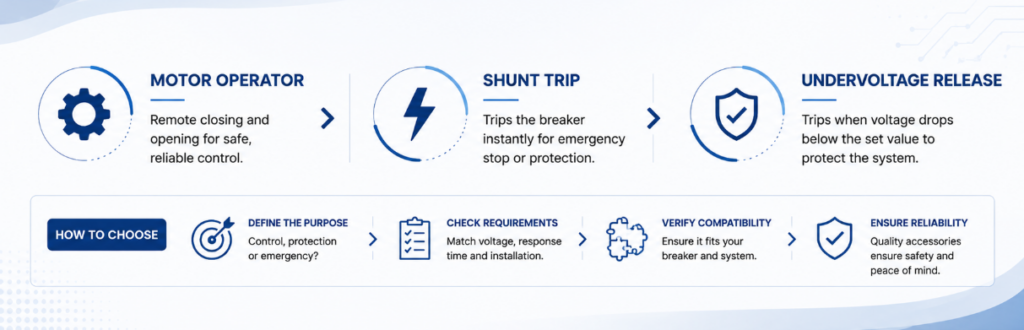
มอเตอร์โอเปอเรเตอร์ เทียบกับ ชันต์ทริป เทียบกับ อันเดอร์โวลเทจรีลีส สำหรับการเลือกอุปกรณ์เสริม MCCBการควบคุมระยะไกลมักถูกระบุเกินความจำเป็น เพราะอุปกรณ์เสริมเหล่านี้ถูกมองว่าใช้แทนกันได้ แต่จริง ๆ แล้วเสริมซึ่งกันและกัน และความเข้าใจผิดที่แพงที่สุดในหมวดนี้คือการซื้อชันต์ทริปแล้วพบว่ามันปิดเบรกเกอร์อีกครั้งไม่ได้.
| ความสามารถ | มอเตอร์โอเปอเรเตอร์ | ชันต์ทริป (MX) | รีลีสแรงดันต่ำ (MN) | หน้าสัมผัสเสริม (OF) |
|---|---|---|---|---|
| ปิดเบรกเกอร์จากระยะไกล | ได้ เมื่อการออกแบบที่เข้าคู่กันอนุญาต | No | No | No |
| เปิดเบรกเกอร์จากระยะไกล | ใช่ | ใช่ | ได้ เมื่อไฟเลี้ยงหาย | No |
| รีเซ็ตหลังทริป | ขึ้นอยู่กับรุ่น — ต้องยืนยัน | No | No | No |
| รายงานตำแหน่งเบรกเกอร์ | ไม่ใช่โดยตัวมันเอง | No | No | ใช่ |
| ต้องใช้ไฟเลี้ยงต่อเนื่อง | ไม่ — ดึงกระแสเฉพาะขณะทำงาน | ไม่ — จ่ายไฟเฉพาะตอนสั่งทริป | ใช่ — ค้างสถานะจ่ายไฟไว้ | ไม่ — หน้าสัมผัสไร้แรงดัน |
| เมื่อไฟเลี้ยงควบคุมหาย | เบรกเกอร์คงสถานะเดิม ควบคุมระยะไกลไม่ได้ | ทริปไม่ได้ | ทริป — fail-safe โดยธรรมชาติ | สถานะหน้าสัมผัสไม่เปลี่ยน |
| บทบาททั่วไป | ตัวสั่งเปิด รีเซ็ต และปิดระยะไกล | เส้นทางทริปสำหรับสัญญาณเตือนอัคคีภัยหรือเหตุฉุกเฉิน | ทริปแบบ fail-safe และการอนุญาตให้ปิด | การยืนยันคำสั่งและอินเตอร์ล็อก |
อ่านสองแถวสุดท้ายประกอบกัน ชันต์ทริปต้องมีไฟเลี้ยงควบคุมที่ปกติจึงจะทำงานได้ ส่วนอันเดอร์โวลเทจรีลีสทำงาน precisely เมื่อไฟเลี้ยงหาย เลือกระหว่างสองอย่างนี้โดยถามว่าควรเกิดอะไรขึ้นหากไฟเลี้ยงควบคุมเองล้มเหลว มอเตอร์โอเปอเรเตอร์ตอบคำถามอีกข้อหนึ่ง: ใครเป็นคนปิดเบรกเกอร์เมื่อไม่มีใครยืนอยู่หน้ามัน.
มอเตอร์โอเปอเรเตอร์อาจเปิดเบรกเกอร์ทางกล และโครงการอาจ ยังคง ต้องใช้ชันต์ทริป เพราะวงจรป้องกันหรือวงจรฉุกเฉินมักต้องการเส้นทางทริปอิสระที่กำหนดไว้ชัดเจน อุปกรณ์ทั้งสองติดตั้งร่วมกัน ไม่ใช่เลือกอย่างใดอย่างหนึ่ง.
มอเตอร์โอเปอเรเตอร์เคลื่อนเบรกเกอร์ได้จริงอย่างไร
คำสั่งไปถึงกลไก มอเตอร์แบบมีเกียร์ทำงาน และเบรกเกอร์เปลี่ยนสถานะ สิ่งที่เกิดขึ้นระหว่างจุดเหล่านั้นแตกต่างกันไปตามการออกแบบ และความแตกต่างนั้นส่งผลต่อระยะเวลาคำสั่ง จังหวะเวลา และสิ่งที่คอนโทรลเลอร์ควรคาดหวังหลังจากไฟดับ.
ไดเรกต์ไดรฟ์. มอเตอร์เคลื่อนอินเทอร์เฟซการทำงานตลอดช่วงชักเต็มขณะที่ได้รับพลังงาน คำสั่งต้องยาวนานพอสำหรับการเคลื่อนที่เต็มระยะ และการเคลื่อนที่ของแอคชูเอเตอร์โดยรวมเป็นไปตามคันเบรกเกอร์ ซึ่งทำให้การทำงานสังเกตได้ง่ายระหว่างการคอมมิชชันนิง.
พลังงานสะสม. มอเตอร์ชาร์จสปริง แล้วสปริงจะถูกปล่อยเพื่อเคลื่อนหน้าสัมผัสในการทำงานเร็วครั้งเดียว สิ่งนี้แยกความเร็วหน้าสัมผัสออกจากความเร็วมอเตอร์ ซึ่งเป็นสิ่งที่ช่วยให้หน้าสัมผัสปิดเร็วพอที่จะจำกัดการอาร์กล่วงหน้า ลำดับการชาร์จและการทำงานของหน้าสัมผัสเป็นสองเหตุการณ์แยกกัน และคอนโทรลเลอร์ควรเผื่อเวลาสำหรับทั้งสองอย่าง.
ไม่มีแนวทางใดดีกว่าแบบสากล คำถามชี้ขาดคือชุดเบรกเกอร์และกลไกทั้งหมดทำงานตามลำดับเปิด รีเซ็ต และปิดที่ต้องการได้หรือไม่ด้วยแหล่งจ่ายควบคุมที่มีอยู่และภายในเวลาของโครงการ ในทั้งสองกรณี มอเตอร์หยุดเมื่อการทำงานเสร็จสิ้น ซึ่งเป็นเหตุผลที่มอเตอร์โอเปอเรเตอร์มีความต้องการชั่วขณะสูงและแทบไม่มีโหลดคงที่.
การทำงานด้วยมือต้องถูกกำหนดไว้อย่างชัดเจนไม่ว่าแบบใดก็ตาม หน้าพอร์ตโฟลิโอ JUTRION ปัจจุบันระบุสวิตช์อัตโนมัติ/มือในตัวสำหรับช่วงกลไกการทำงานแบบมอเตอร์ ยืนยันการเข้าประกอบเชิงกลของรุ่นที่สั่ง ว่าโหมดมือบล็อกคำสั่งระยะไกลหรือไม่ ว่าตัดไฟมอเตอร์หรือไม่ และคอนโทรลเลอร์รับฟีดแบ็กตำแหน่งตัวเลือกหรือไม่ ตัวเลือกมือไม่ใช่อุปกรณ์แยกวงจรและต้องประสานกับขั้นตอนการล็อกของตู้.
สร้างห่วงโซ่คำสั่ง การอนุญาต การเคลื่อนที่ และฟีดแบ็ก
วงจรควบคุมมอเตอร์ที่เชื่อถือได้มีฟังก์ชันเชื่อมโยงสี่อย่าง แต่ละอย่างต้องการอินพุต เอาต์พุต การตอบสนองเมื่อล้มเหลว และการทดสอบคอมมิชชันนิงที่กำหนดไว้.
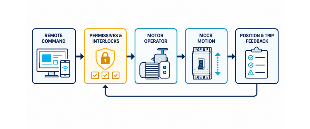
ห่วงโซ่ควบคุมกลไกการทำงานแบบมอเตอร์ของ MCCB แสดงคำสั่งระยะไกล เงื่อนไขอนุญาตและอินเทอร์ล็อก การเคลื่อนที่ของเบรกเกอร์ และฟีดแบ็กตำแหน่งและทริปคำสั่ง
- คำสั่งอาจมาจากปุ่มกดเฉพาะที่ เอาต์พุต PLC รีเลย์ BMS คอนโทรลเลอร์ถ่ายโอน หรือรีเลย์ป้องกัน กำหนดว่ากลไกคาดหวังพัลส์ สัญญาณคงค้าง หรืออินพุตเปิดและปิดแยกกัน อย่าอนุมานการจัดเรียงจากแรงดันควบคุม คำสั่งต้องแยกจากกัน: หากเปิดและปิดสามารถถูกจ่ายพลังงานพร้อมกันได้ผ่านรีเลย์ทับซ้อนหรือข้อผิดพลาดซอฟต์แวร์ วงจรต้องแก้ไขความขัดแย้งอย่างคาดเดาได้.
การอนุญาต
- คำสั่งคือคำขอ ไม่ใช่อำนาจในการจ่ายไฟให้วงจร เงื่อนไขอนุญาตให้ปิดโดยทั่วไปรวมถึงแรงดันแหล่งจ่ายที่สมบูรณ์ ไม่มีการล็อกเอาต์ที่ทำงานอยู่ เบรกเกอร์ไม่อยู่ในโหมดซ่อมบำรุง แหล่งจ่ายสำรองเปิดอยู่ สาเหตุการทริปถูกเคลียร์แล้ว และสวิตช์เลือกอยู่ในตำแหน่งรีโมท การเปิดมักมีเงื่อนไขอนุญาตน้อยกว่า แต่ตรรกะที่จำเป็นยังคงต้องอยู่ในเอกสารเหตุและผลของโครงการ ไม่ใช่ดุลยพินิจของผู้ติดตั้ง.
การเคลื่อนที่
- เมื่อได้รับอนุญาตแล้ว กลไกจะดึงกำลังควบคุมและเคลื่อนเบรกเกอร์ แหล่งจ่ายต้องรักษาแรงดันไว้ได้ตลอดความต้องการชั่วขณะนั้น แหล่งจ่ายที่วัดค่าได้ถูกต้องขณะหยุดนิ่งอาจแรงดันตกเมื่อมอเตอร์สตาร์ท ทำให้การทำงานไม่สมบูรณ์ เผื่อเวลาทำงานที่ผู้ผลิตประกาศไว้บวกระยะขอบสำหรับการตรวจสอบ และห้ามออกคำสั่งซ้ำอย่างรวดเร็วเพื่อบังคับให้ทำงานสำเร็จ.
การป้อนกลับ
- ยืนยันสถานะทางกายภาพหลังออกคำสั่ง หน้าสัมผัสตำแหน่งระบุ ON หรือ OFF หน้าสัมผัสสัญญาณเตือนแยกต่างหากใช้แยกการทริปป้องกันออกจากการเปิดตามคำสั่ง หากคำสั่งหมดอายุโดยไม่มีสถานะตามที่คาดไว้ ให้แจ้งเตือน failure-to-open หรือ failure-to-close และบล็อกการลองซ้ำ นั่นเปลี่ยนความล้มเหลวแบบเงียบให้เป็นข้อมูลวินิจฉัยที่นำไปใช้ได้.
ขนาดแหล่งจ่ายควบคุมตามกระแสกระชากขณะดูด ไม่ใช่โหลดค้าง
นี่คือการคำนวณที่มักถูกข้ามบ่อยที่สุด และเป็นสิ่งที่แยกแผงที่ทำงานได้ออกจากแผงที่ล้มเหลวเป็นครั้งคราว คอยล์อุปกรณ์เสริมดึงกระแสต่างกันสองแบบอย่างมาก.
- VA ขณะดูด (กระแสกระชาก) — กระแสกระชากช่วงสั้นขณะคอยล์จ่ายพลังงานและมอเตอร์สตาร์ท เป็นตัวกำหนดความสามารถชั่วขณะที่แหล่งจ่ายต้องมี และแรงดันตกที่อุปกรณ์อื่นบนแหล่งจ่ายเดียวกันจะเห็น.
- VA ขณะค้าง — กระแสต่อเนื่องเมื่อจ่ายพลังงานแล้ว เป็นตัวกำหนดโหลดความร้อนคงที่.
แหล่งจ่ายที่รองรับโหลดค้างได้สบายแต่แรงดันตกขณะดูด จะทำให้คอยล์ปลด หรือไม่สามารถดึงเข้าได้เลย อุปกรณ์ไม่ได้เสีย แหล่งจ่ายมีขนาดเล็กเกินไปสำหรับความต้องการที่กินเวลาเพียงเสี้ยววินาที.
ความต้องการสูงสุด (ขณะดูด):
VA สูงสุด = Σ (VA ขณะดูด × จำนวน)
กระแสสูงสุดที่แรงดันคอยล์:
Iสูงสุด = VA สูงสุด / V
ความต้องการคงที่ (ขณะค้าง):
VA คงที่ = Σ (VA ขณะค้าง × จำนวน)
พิกัดแหล่งจ่ายที่แนะนำ:
แหล่งจ่ายเบื้องต้นตัวอย่าง = VA สูงสุด × 1.25
ตัวคูณ 1.25 เป็นค่าประมาณที่ใช้ในเครื่องคิดเลขของ JUTRION ไม่ใช่ข้อกำหนดสากลที่ระบุโดย IEC 60947-2 ให้เปลี่ยนค่าตัวนี้หากผู้ผลิตแหล่งจ่ายไฟ ข้อมูลหม้อแปลงควบคุม มาตรฐานโครงการ ภาระงาน อุณหภูมิ หรือการศึกษาการทำงานพร้อมกันต้องการค่ากำลังสำรองที่แตกต่างกัน
เมื่ออุปกรณ์เสริมหลายตัวสามารถจ่ายพลังงานพร้อมกันได้ — มอเตอร์โอเปอเรเตอร์ทำงานรอบของมันขณะที่ undervoltage release ถูกค้างไว้ — ให้นำค่าขณะดูดมารวมกัน การรวมกันนั้น ไม่ใช่อุปกรณ์ตัวใดตัวหนึ่ง คือกรณีเลวร้ายที่สุด เครื่องคำนวณกำลังอุปกรณ์เสริมเบรกเกอร์ JUTRION คำนวณสมการเหล่านี้โดยตรง.
| อุปกรณ์เสริม | VA ขณะดูด | กระแสค้าง (VA) | รอบการทำงาน |
|---|---|---|---|
| มอเตอร์โอเปอเรเตอร์ | ประมาณ 300–600 | 0 | ดึงกระแสเฉพาะระหว่างรอบการทำงาน |
| ชันต์ทริป (MX) | ประมาณ 100–300 | 0 | ชั่วขณะ; จ่ายไฟเฉพาะเมื่อสั่งทริป |
| รีลีสแรงดันต่ำ (MN) | ประมาณ 200–350 | ประมาณ 5–10 | จ่ายพลังงานต่อเนื่อง |
| หน้าสัมผัสเสริม / แจ้งเตือน | เล็กน้อยมาก | เล็กน้อยมาก | หน้าสัมผัสไร้แรงดัน |
เหล่านี้คือช่วงค่าเริ่มต้นตัวอย่างที่เผยแพร่โดยเครื่องคำนวณ JUTRION ไม่ใช่ค่า IEC หรือพิกัดของผลิตภัณฑ์ที่สั่งซื้อ ความต้องการของคอยล์แตกต่างกันตามซีรีส์ ขนาดเฟรม และชนิด AC หรือ DC ดังนั้นให้เปลี่ยนค่าเริ่มต้นทุกค่าด้วยตัวเลขจากเอกสารข้อมูลของอุปกรณ์ที่สั่งซื้อจริง ตารางนี้มีประโยชน์สำหรับทำความเข้าใจหน้าที่ขณะดูดเทียบกับขณะค้าง ไม่ใช่สำหรับออกข้อกำหนดหม้อแปลงหรือแหล่งจ่ายไฟขั้นสุดท้าย.
ตรวจสอบแรงดันตกก่อนเลือกคอยล์ 24 V DC
ไฟ DC แรงดันต่ำมักถูกกำหนดเพื่อความเข้ากันได้กับราง PLC หรือแหล่งจ่ายควบคุมที่สำรองด้วย UPS สำหรับมอเตอร์โอเปอเรเตอร์ควรพิจารณาใหม่: กำลังเท่ากันที่แรงดันต่ำกว่าหมายถึงกระแสที่เพิ่มขึ้นตามสัดส่วน และแรงดันตกก็เพิ่มขึ้นตามไปด้วย.
สำหรับวงจรควบคุม DC แบบสองสาย:
ΔU = 2 × L × I × ρ / A
โดยที่ ΔU คือแรงดันตกในหน่วยโวลต์ (V), L คือระยะทางเดินสายทางเดียวในหน่วยเมตร (m), I คือกระแสทำงานในหน่วยแอมป์ (A), ρ คือความต้านทานจำเพาะของทองแดง (ประมาณ 0.0175 Ω·mm²/m ที่ 20 °C เพิ่มขึ้นตามอุณหภูมิ) และ A คือพื้นที่หน้าตัดตัวนำในหน่วย mm² จัดเรียงใหม่สำหรับระยะทางที่อนุญาต:
Lสูงสุด = ΔU × A / (2 × I × ρ)
สำหรับการเปรียบเทียบเชิงตัวอย่าง สมมติกลไกที่มีความต้องการตอนสตาร์ท 450 VA และอนุญาตให้แรงดันตก 10% ค่า 450 VA เป็นค่าที่สร้างขึ้นภายในช่วงทั่วไปของเครื่องคำนวณ ไม่ใช่พิกัดรุ่นของ JUTRION:
| แรงดันคอยล์ | กระแสตอนสตาร์ท | แรงดันตกที่อนุญาต | ระยะทางสูงสุดบนสาย 2.5 mm² | ระยะทางสูงสุดบนสาย 6 mm² |
|---|---|---|---|---|
| DC 24 V | 18.8 A | 2.4 V | ประมาณ 9 เมตร | ประมาณ 22 เมตร |
| DC 110 V | 4.1 A | 11 V | ประมาณ 192 เมตร | ประมาณ 460 เมตร |
| AC 220 V | 2.0 A | 22 V | ประมาณ 768 เมตร | ประมาณ 1844 เมตร |
ภายใต้สมมติฐานเฉพาะเหล่านี้ ตัวเลือก DC 24 V บนตัวนำ 2.5 mm² ถึงขีดจำกัดแรงดันตก 10% ที่ประมาณเก้าเมตร นี่ไม่ใช่ขีดจำกัดความยาวสายสากล: ผลลัพธ์เปลี่ยนแปลงโดยตรงตามความต้องการตอนสตาร์ทของกลไกที่สั่งซื้อ ขนาดตัวนำ อุณหภูมิ การสูญเสียที่ขั้วต่อ และช่วงแรงดันทำงานที่อนุญาต สำหรับระยะทางไกลจากห้องควบคุม ให้เปรียบเทียบตัวนำที่ใหญ่กว่า แหล่งจ่ายเฉพาะที่เบรกเกอร์ และแรงดันควบคุมที่สูงขึ้น.
นี่คือเหตุผลที่คอยล์เสริมมีให้เลือกในช่วงแรงดันกว้างเช่นนี้ กลไกการทำงานด้วยมอเตอร์ของ JUTRION มีให้เลือกใน AC 110 V, AC 220 V และ AC 400 V และใน DC 24 V, DC 36 V, DC 110 V และ DC 220 V เพื่อให้สามารถเลือกแรงดันควบคุมให้เหมาะกับระยะสายแทนที่จะเลือกสายตามแรงดันที่ติดเป็นนิสัย.
ตัวอย่างการคำนวณ: ฟีดเดอร์ 400 A พร้อมมอเตอร์โอเปอเรเตอร์ระยะไกล
การใช้งาน. เบรกเกอร์ MCCB ขนาด 400 A จ่ายไฟให้สถานีสูบน้ำจากห้องควบคุมที่อยู่ห่างออกไปประมาณ 60 เมตร เบรกเกอร์ต้องเปิด รีเซ็ต และปิดจากระยะไกล มีอุปกรณ์ปลดแรงดันต่ำติดตั้งอยู่เพื่อให้เบรกเกอร์ทริปเมื่อสูญเสียแหล่งจ่ายควบคุม.
ขั้นตอนที่ 1 — ระบุสิ่งที่สามารถจ่ายไฟพร้อมกันได้. มอเตอร์โอเปอเรเตอร์ทำงานรอบการทำงานในขณะที่อุปกรณ์ปลดแรงดันต่ำถูกค้างไว้ ทั้งสองอยู่บนแหล่งจ่ายควบคุมเดียวกัน ดังนั้นจึงนับทั้งคู่.
ขั้นตอนที่ 2 — กำหนดค่าตัวอย่าง. สมมติว่ามอเตอร์โอเปอเรเตอร์มีค่า 450 VA สำหรับการดึงใช้งาน / 0 สำหรับการถือ และการปล่อยแรงดันต่ำที่ 275 VA สำหรับการดึงใช้งาน / 7 VA สำหรับการถือ ค่าที่สร้างขึ้นเหล่านี้อยู่ในช่วงประมาณของเครื่องคิดเลข JUTRION; ให้เปลี่ยนเป็นค่าจากแผ่นข้อมูลอุปกรณ์เสริมที่สั่งซื้อ
ขั้นตอนที่ 3 — ความต้องการสูงสุด.
ค่า VA สูงสุด = (450 × 1) + (275 × 1) = 725 VA
ขั้นตอนที่ 4 — ความต้องการคงที่.
ค่า VA คงที่ = (0 × 1) + (7 × 1) = 7 VA
อัตราส่วนคือบทเรียน: ความต้องการชั่วขณะมากกว่าความต้องการต่อเนื่องมากกว่าร้อยเท่า.
ขั้นตอนที่ 5 — ขนาดแหล่งจ่าย.
แหล่งจ่ายตัวอย่าง = 725 × 1.25 = 906 VA
ขั้นตอนที่ 6 — ตรวจสอบแรงดันเทียบกับระยะทาง. ที่ DC 24 V กระแสสูงสุดคือ 725 / 24 = 30.2 A และการรักษาระดับแรงดันตก 10 % ตลอดระยะ 60 ม. จะต้องใช้สายประมาณ 26 mm² — ซึ่งไม่เหมาะสมสำหรับวงจรควบคุม ที่ AC 220 V กระแสสูงสุดคือ 725 / 220 = 3.3 A และสาย 2.5 mm² ก็เพียงพอพร้อมระยะเผื่อ.
ผลลัพธ์เชิงตัวอย่าง: AC 220 V เป็นตัวเลือกที่ใช้งานได้จริงมากกว่าสำหรับระยะ 60 ม. ที่สมมติขึ้น หม้อแปลงควบคุมประมาณ 1 kVA และตัวนำขนาด 2.5 mm² เป็นผลลัพธ์เบื้องต้นภายใต้ข้อมูลที่ระบุ การเลือกขั้นสุดท้ายต้องพิจารณาการควบคุมแรงดันระยะสั้นของหม้อแปลง การป้องกัน วิธีการติดตั้ง อุณหภูมิ ข้อมูลอุปกรณ์จริง และช่วงแรงดันที่อนุญาต ที่ DC 24 V ตัวอย่างนี้ชี้ให้เห็นถึงความจำเป็นในการใช้แหล่งจ่ายเฉพาะที่หรือตัวนำที่มีขนาดใหญ่กว่าอย่างมีนัยสำคัญ.
การปิดอัตโนมัติต้องมีเงื่อนไขอนุญาต การล็อกระหว่างกัน และนโยบายการรีเซ็ต
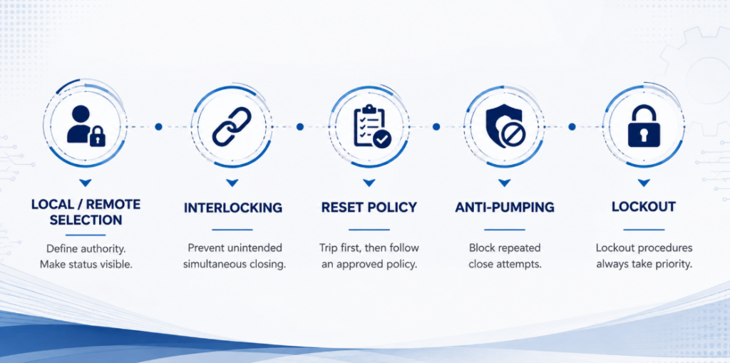
เงื่อนไขอนุญาตการปิดอัตโนมัติ การล็อกแหล่งจ่ายระหว่างกัน นโยบายการรีเซ็ต การป้องกันการปิดซ้ำ และการล็อกเพื่อการบำรุงรักษาการเปิดระยะไกลเป็นเรื่องตรงไปตรงมา การปิดระยะไกลอาจทำให้อุปกรณ์ที่เสียหายได้รับพลังงาน เริ่มเครื่องจักรใหม่ ขนานแหล่งจ่าย หรือทำให้ผู้ที่เชื่อว่าวงจรจะยังคงเปิดอยู่ตกอยู่ในอันตราย เส้นทางการปิดสมควรได้รับความใส่ใจทางวิศวกรรมมากกว่ามอเตอร์.
การเลือกโหมดท้องถิ่น/ระยะไกล. สวิตช์เลือกกำหนดผู้มีอำนาจ สถานะของสวิตช์ควรปรากฏต่อตัวควบคุม เพื่อให้คำสั่งที่ถูกบล็อกแสดงข้อความ “โหมดท้องถิ่น” ที่ชัดเจน แทนที่จะเป็นสัญญาณเตือนความผิดพลาดทั่วไป.
การล็อกแหล่งจ่ายระหว่างกัน. ในกรณีที่เบรกเกอร์สองตัวใช้เลือกแหล่งจ่ายระหว่างยูทิลิตี้ เครื่องกำเนิดไฟฟ้า หรือบัส ตรรกะต้องป้องกันการปิดพร้อมกันโดยไม่ตั้งใจ เว้นแต่ระบบถูกออกแบบให้ขนานกัน การล็อกเชิงกลเพิ่มชั้นการป้องกันทางกายภาพ แต่ต้องตรวจสอบความเข้ากันได้กับเบรกเกอร์และกลไกที่เลือก.
นโยบายการรีเซ็ตและการปิดซ้ำ. การทริปเพื่อป้องกันโดยปกติควรบล็อกการปิดอัตโนมัติจนกว่าสาเหตุจะถูกจำแนก บางระบบอนุญาตให้ปิดซ้ำภายใต้การควบคุมหนึ่งครั้งสำหรับเหตุการณ์ชั่วคราวที่กำหนด บางระบบต้องมีการตรวจสอบหลังการทริปทุกครั้ง มอเตอร์โอเปอเรเตอร์ดำเนินการตามนโยบายที่อนุมัติ — ไม่ควรสร้างนโยบายเองโดยค่าเริ่มต้น.
การป้องกันการปิดซ้ำ (Anti-pumping). หากคำสั่ง CLOSE ยังคงอยู่ขณะที่เบรกเกอร์ทริป ระบบต้องไม่หมุนเวียนระหว่างการปิดและการทริป สถาปัตยกรรมการควบคุมควรบล็อกความพยายามซ้ำ ๆ จนกว่าคำสั่งจะถูกยกเลิกและลำดับที่ได้รับอนุญาตใหม่เริ่มต้นขึ้น.
การล็อกเพื่อการบำรุงรักษา. การยับยั้งด้วยซอฟต์แวร์ไม่ใช่สิ่งทดแทนขั้นตอนการล็อกที่ได้รับการอนุมัติ ระบบระยะไกลสามารถออกคำสั่งโดยไม่คาดคิดระหว่างการทดสอบ การกู้คืนการสื่อสาร หรือการรีสตาร์ทซอฟต์แวร์.
นำตรรกะไปใช้กับสถาปัตยกรรมทั่วไปสามแบบ
เครื่องกำเนิดไฟฟ้าและการถ่ายโอนแหล่งจ่าย
เบรกเกอร์สองตัว แต่ละตัวมีมอเตอร์โอเปอเรเตอร์ ถูกสลับโดยตัวควบคุมการถ่ายโอนเพื่อให้มีเพียงตัวเดียวที่ปิดอยู่ตลอดเวลา มอเตอร์โอเปอเรเตอร์จำเป็นเพราะตัวควบคุมต้อง ปิด ปิดเบรกเกอร์ ไม่ใช่เพียงแค่ทริปตัวหนึ่ง.
ตัวควบคุมเปิดแหล่งจ่ายที่ใช้งานอยู่ ยืนยันว่าเปิดแล้วผ่านการตอบกลับตำแหน่ง และจากนั้นจึงอนุญาตให้แหล่งจ่ายสำรองปิด การล็อกระหว่างกันเป็นข้อบังคับ แหล่งจ่ายควบคุมต้องพร้อมใช้งานจากแหล่งจ่ายใดก็ตามที่ยังมีไฟ — รายละเอียดที่มักถูกมองข้ามเมื่อหม้อแปลงควบคุมได้รับไฟจากฝั่งยูทิลิตี้เพียงฝั่งเดียว.
ความแตกต่างที่สำคัญ: มอเตอร์โอเปอเรเตอร์ให้การเคลื่อนที่ มันไม่ได้ทำให้เบรกเกอร์สองตัวกลายเป็นสวิตช์ถ่ายโอนด้วยตัวมันเอง.
สถานที่ที่ไม่มีคนดูแลหรือสถานีไฟฟ้าย่อยระยะไกล
เบรกเกอร์ในห้องเครื่องบนดาดฟ้า สถานีสูบน้ำ หรือสถานีไฟฟ้าย่อยที่ไม่มีคนควบคุมถูกติดตั้งมอเตอร์เพื่อให้สามารถตรวจสอบการทริปและฟื้นฟูแหล่งจ่ายได้โดยไม่ต้องเดินทางไปยังสถานที่ ระยะสายเคเบิลมักยาว ซึ่งทำให้การตัดสินใจเรื่องแรงดันควบคุมเป็นข้อจำกัดหลักแทนที่จะเป็นกลไก ติดตั้งหน้าสัมผัสสัญญาณเตือนควบคู่กับหน้าสัมผัสตำแหน่ง เพื่อให้ระบบควบคุมสามารถแยกความแตกต่างระหว่างการทริปจากความผิดพลาดและการเปิดตามคำสั่ง ก่อนที่ใครจะพยายามรีเซ็ตระยะไกล.
การตัดโหลดและการสลับตามกำหนดการ
ระบบจัดการพลังงานเปิดวงจรป้อนที่ไม่สำคัญเมื่อความจุของเครื่องกำเนิดไฟฟ้าหรือความต้องการของสถานที่ถึงขีดจำกัด จากนั้นฟื้นฟูเป็นขั้นตอนเพื่อหลีกเลี่ยงความต้องการสูงสุดครั้งที่สอง แต่ละวงจรป้อนต้องมีลำดับความสำคัญ เวลาปิดขั้นต่ำ เงื่อนไขอนุญาตการปิด และสัญญาณเตือนความผิดพลาด.
การเปิดหนึ่งครั้งและการปิดหนึ่งครั้งต่อวันรวมประมาณ 10,950 ครั้งในสิบห้าปี ยืนยันว่ากลไกที่สั่งซื้อนิยามการทำงานหรือรอบอย่างไรก่อนเปรียบเทียบตัวเลขนี้กับความทนทาน การสลับตามปกติบ่อยครั้งอาจเหมาะกับคอนแทคเตอร์ โดยให้เบรกเกอร์ทำหน้าที่ป้องกันและแยกวงจร.
การติดตั้งมอเตอร์โอเปอเรเตอร์ย้อนหลังกับเบรกเกอร์ที่ติดตั้งอยู่แล้ว
งานเขียนส่วนใหญ่ในหัวข้อนี้สมมติว่าเบรกเกอร์และอุปกรณ์เสริมถูกระบุพร้อมกัน ส่วนใหญ่ของคำถามจริงกลับตรงกันข้าม: เบรกเกอร์ใช้งานมาหลายปีแล้ว ความต้องการการทำงานระยะไกลเกิดขึ้นทีหลัง และคำถามคือสามารถเพิ่มกลไกได้โดยไม่ต้องเปลี่ยนเบรกเกอร์หรือไม่.
MCCB บางรุ่นที่ติดตั้งแล้วสามารถรับโอเปอเรเตอร์แบบติดตั้งเพิ่มเติมได้โดยไม่ต้องเปลี่ยนเบรกเกอร์ เมื่อกลไกที่ได้รับการอนุมัติติดตั้งที่ด้านหน้า เส้นทางกระแสและการตั้งค่าการตัดวงจรอาจไม่เปลี่ยนแปลง แต่ต้องแยกแผงและตรวจสอบสภาพเบรกเกอร์ก่อนการติดตั้ง มีสามปัจจัยที่กำหนดว่าการติดตั้งเพิ่มเติมนั้นเป็นไปได้หรือไม่:
- ซีรีส์และเฟรม. กลไกถูกจับคู่กับเบรกเกอร์เฉพาะ ไม่ใช่พิกัดกระแส เบรกเกอร์ 250 A สองตัวจากซีรีส์ต่างกันมักต้องใช้กลไกที่แตกต่างกัน.
- ระยะห่างด้านหน้า. มอเตอร์โอเปอเรเตอร์เพิ่มความลึก ตรวจสอบระยะห่างถึงประตูตู้และถึงแผ่นครอบก่อนสั่งซื้อ.
- แหล่งจ่ายควบคุม. แผงที่มีอยู่อาจไม่มีหม้อแปลงควบคุมหรือแหล่งจ่าย DC หรือมีแต่ไม่มีความจุตามที่คำนวณข้างต้น ในการติดตั้งย้อนหลัง นี่มักเป็นข้อจำกัดจริงมากกว่ากลไก.
ยี่ห้อไม่ใช่อุปสรรคอัตโนมัติ การปรับเฉพาะรุ่นสามารถครอบคลุมประมาณ 99% ของการออกแบบเบรกเกอร์กระแสหลัก โดยอินเทอร์เฟซการติดตั้ง เค้าโครงขั้วต่อ และแรงดันคอยล์ถูกจับคู่กับเบรกเกอร์เป้าหมาย เปอร์เซ็นต์นี้อธิบายความกว้างของโปรแกรมการปรับ ไม่ได้หมายความว่ากลไกสากลหนึ่งตัวพอดีกับ MCCB ทุกตัว.
การตรวจสอบความเข้ากันได้: บันทึกผู้ผลิตเบรกเกอร์ ซีรีส์ เฟรม และจำนวนขั้ว จากนั้นให้รูปถ่ายป้ายชื่อและมุมมองด้านหน้าที่ชัดเจน ข้อมูลเหล่านี้ช่วยให้ตรวจสอบอินเทอร์เฟซการติดตั้งและระยะการเคลื่อนที่ก่อนเลือกกลไก.
เบรกเกอร์ที่ยังใช้งานได้อาจได้รับการควบคุมระยะไกลโดยไม่ต้องเปลี่ยนใหม่ ขึ้นอยู่กับสภาพ พื้นที่ว่าง เอกสารที่ต้องใช้ และความเข้ากันได้ของกลไกที่ได้รับการอนุมัติ.
ตรวจสอบตัวเลือกอุปกรณ์เสริมที่รองรับ
ชุดอุปกรณ์เสริมครบชุด ช่วงอุปกรณ์เสริมสำหรับ MCB และ MCCB อาจรวมถึงกลไกการทำงานด้วยมอเตอร์ ตัวปลด shunt ตัวปลดแรงดันต่ำ หน้าสัมผัสเสริม และหน้าสัมผัสสัญญาณเตือน ตารางด้านล่างเปรียบเทียบฟังก์ชันด้านการควบคุม แต่การติดตั้งเชิงกล仍需ต้องยืนยันกับป้ายชื่อเบรกเกอร์.
| อุปกรณ์เสริม | ตัวเลือกแรงดันไฟฟ้าควบคุม | การกำหนดค่า | ความทนทานที่กำหนด |
|---|---|---|---|
| กลไกการทำงานด้วยมอเตอร์ | AC 110 V, AC 220 V, AC 400 V; DC 24 V, DC 36 V, DC 110 V, DC 220 V | สวิตช์เลือกโหมดอัตโนมัติ/ manual ในตัว | 10,000 ครั้งของการสั่งงานระยะไกล |
| ชุดตัดวงจรระยะไกล (MX / ST) | AC 230 V, AC 400 V; DC 24 V | การตัดวงจรทันที | 4,000 ครั้งของการตัดวงจร |
| อุปกรณ์ปลดแรงดันต่ำ (MN / UVR) | AC 230 V, AC 400 V; DC 24 V, DC 48 V | ปลดที่ 35 %–70 % Un | 4,000 ครั้งของการตัดวงจร |
| หน้าสัมผัสเสริม (OF) | ไม่มีแรงดันไฟฟ้า | 1 NO + 1 NC หรือ 2 NO + 2 NC | 10,000 รอบทางไฟฟ้า |
| หน้าสัมผัสสัญญาณเตือน (SD) | ไม่มีแรงดันไฟฟ้า | 1 NO + 1 NC หรือ 2 NO + 2 NC | 10,000 รอบทางไฟฟ้า |
ช่วงแรงดันไฟฟ้ากว้างช่วยให้แหล่งจ่ายควบคุมเป็นไปตามการติดตั้ง ภายในตู้สวิตช์เดียว DC 24 V สามารถรวมเข้ากับลอจิก PLC ได้อย่างสะดวก สำหรับระยะทางไกล แรงดันควบคุมที่สูงขึ้นอาจลดความต้องการตัวนำไฟฟ้า.
ตัวเลขที่เผยแพร่ในกลุ่มผลิตภัณฑ์ระบุ 10,000 ครั้งของการสั่งงานระยะไกลสำหรับหมวดกลไก และ 4,000 ครั้งของการตัดวงจรสำหรับอุปกรณ์เสริมการตัด ตรวจสอบว่าโมเดลที่สั่งซื้อกำหนดและทดสอบการทำงานอย่างไรก่อนเปรียบเทียบกับภาระงานของโครงการ ใช้ คอนแทคเตอร์ เมื่อต้องการสวิตชิ่งเป็นประจำบ่อยครั้ง.
หลีกเลี่ยงข้อผิดพลาดแปดประการที่ทำให้มอเตอร์โอเปอเรเตอร์ล้มเหลว
| ข้อผิดพลาด | ผลลัพธ์ | การป้องกัน |
|---|---|---|
| การระบุชุดตัดวงจรระยะไกลสำหรับ “การควบคุมระยะไกล” | ตัดวงจรระยะไกลได้ แต่ต้องปิดด้วยมือที่แผง | ตรวจสอบก่อนว่าต้องการการปิดระยะไกลหรือไม่ |
| การสันนิษฐานว่าการปิดระยะไกลรวมถึงการรีเซ็ตจากสถานะ TRIPPED | เบรกเกอร์จะไม่ปิดหลังจากการตัดวงจรเนื่องจากข้อบกพร่อง | ระบุ “รีเซ็ตระยะไกลหลังการตัดวงจร” อย่างชัดเจนในข้อกำหนด |
| การกำหนดขนาดแหล่งจ่ายควบคุมจากค่า VA ขณะค้าง | กลไกไม่สามารถดึงเข้าได้ มีอาการเป็นช่วงๆ | กำหนดขนาดจากความต้องการดึงเข้ารวม และใช้ระยะเผื่อของโครงการที่บันทึกไว้ |
| การเลือก DC 24 V สำหรับระยะทางไกล | แรงดันตกทำให้การทำงานไม่น่าเชื่อถือ ถูกวินิจฉัยผิดว่าเป็นกลไกเสีย | ตรวจสอบแรงดันตกที่ระยะจริงก่อนกำหนดแรงดันไฟฟ้า |
| การละเลยการทำงานของอุปกรณ์เสริมพร้อมกัน | แหล่งจ่ายที่เพียงพอสำหรับอุปกรณ์หนึ่งตัวเกิดตกเมื่อสองตัวทำงานพร้อมกัน | เพิ่มค่า VA ขณะดึงเข้าของทุกสิ่งที่สามารถทำงานพร้อมกันได้ |
| จับคู่จากพิกัดแอมแปร์เพียงอย่างเดียว | อุปกรณ์เสริมไม่สามารถติดตั้งได้ หรือชนกับประตู | ตรวจสอบซีรีส์ โครง และระยะห่างจากแผ่นป้ายชื่อ |
| การละเว้นหน้าสัมผัสการตัด/สัญญาณเตือนแยก | ระบบไม่สามารถแยกแยะการตัดวงจรจากข้อบกพร่องกับการเปิดที่สั่งการ และอาจปิดซ้ำบนข้อบกพร่อง | ติดตั้งหน้าสัมผัสตำแหน่งและสัญญาณเตือน และเดินสายทั้งสอง |
| การปล่อยสวิตช์เลือกไว้ที่ MANUAL หลังการติดตั้งเสร็จ | คำสั่งระยะไกลถูกเพิกเฉยอย่างเงียบๆ | ตรวจสอบและบันทึกตำแหน่งสวิตช์เลือกเมื่อส่งมอบ |
วินิจฉัยความล้มเหลวโดยติดตามสายโซ่ควบคุม
| อาการ | พื้นที่ที่อาจเป็นปัญหา | หลักฐานที่ต้องเก็บ | การดำเนินการถัดไปที่ปลอดภัย |
|---|---|---|---|
| มอเตอร์ไม่ทำงาน | ขาดแหล่งจ่าย สวิตช์เลือกอยู่ที่ MANUAL ไม่มีคำสั่ง เงื่อนไขอนุญาตเปิดอยู่ ฟิวส์ควบคุมขาด | แรงดันที่ขั้วแหล่งจ่ายและขั้วคำสั่ง สถานะสวิตช์เลือกและ PLC | ตรวจสอบคำสั่งและเงื่อนไขอนุญาตก่อนเปลี่ยนอะไร |
| มอเตอร์ทำงาน แต่เบรกเกอร์ไม่เปลี่ยนสถานะ | ความไม่ตรงกันทางกล การจัดตำแหน่งผิด เบรกเกอร์ยังอยู่ในสถานะ TRIPPED การรีเซ็ตไม่สมบูรณ์ | การแสดงผลเบรกเกอร์; การเคลื่อนที่ด้วยมือ; การจัดตำแหน่ง | แยกแหล่งจ่ายควบคุมและตรวจสอบอินเทอร์เฟซเชิงกล |
| เบรกเกอร์ถึงตำแหน่งแต่ PLC แสดงความล้มเหลว | คอนแทกต์เสริมผิด, การตีความ NO/NC ผิด, สายป้อนกลับขาด, ตัวจับเวลาสั้นเกินไป | สถานะคอนแทกต์ที่เบรกเกอร์และคอนโทรลเลอร์; เวลาทำงานที่วัดได้ | แก้ไขลอจิกป้อนกลับแทนที่จะขยายตัวจับเวลาอย่างไม่ยั้งคิด |
| แรงดันควบคุมทรุดตัวระหว่างการเคลื่อนที่ | แหล่งจ่ายขนาดเล็กเกินไป, ระยะทางไกล, ตัวนำเล็ก, โหลดพร้อมกัน | แรงดันต่ำสุด ที่กลไก ระหว่างการทำงาน | แก้ไขวงจรจ่ายไฟโดยใช้ข้อมูลเฉพาะรุ่น |
| ทำงานในพื้นที่ แต่ไม่ทำงานจากห้องควบคุม | แรงดันตกตลอดระยะทางไกล, ขั้วต่อหลวมที่จุดรวมสาย | คำนวณแรงดันตกใหม่ตามขนาดและความยาวจริง; ตรวจสอบจุดเชื่อมต่อ | ปรับขนาดตัวนำหรือเปลี่ยนแรงดันควบคุม |
| เบรกเกอร์ปิดและทริปซ้ำๆ | ฟอลต์ไม่ถูกเคลียร์, คำสั่งปิดค้างอยู่, ขาดลอจิกป้องกันการปิดซ้ำ | การแสดงผลทริป, ประวัติคำสั่ง, เหตุการณ์การป้องกัน | บล็อกการปิดซ้ำและตรวจสอบวงจรที่ได้รับการป้องกัน |
อย่าเริ่มการวินิจฉัยโดยการบายพาสเงื่อนไขอนุญาตหรือบังคับที่จับ ระบุก่อนว่าฟังก์ชันใดในสี่อย่างล้มเหลว — คำสั่ง, เงื่อนไขอนุญาต, การเคลื่อนที่ หรือการป้อนกลับ ซึ่งจะป้องกันไม่ให้ความผิดพลาดของลอจิกควบคุมถูกเข้าใจผิดว่าเป็นความล้มเหลวเชิงกล และป้องกันการทำงานซ้ำกับเบรกเกอร์ที่ถูกบล็อกหรือทริปแล้ว.
บันทึกพารามิเตอร์เหล่านี้ก่อนเลือกกลไก
- รูปถ่ายป้ายชื่อเบรกเกอร์ — ระบุยี่ห้อ, ซีรีส์, โครงและพิกัดในขั้นตอนเดียว
- ยี่ห้อเบรกเกอร์, ซีรีส์และรุ่น หากไม่สามารถเข้าถึงป้ายชื่อได้
- จำนวนขั้วและทิศทางการติดตั้ง
- ฟังก์ชันที่ต้องการ: เปิดระยะไกล, รีเซ็ตระยะไกลหลังทริป, ปิดระยะไกล หรือทั้งสามอย่าง
- แรงดันควบคุมที่มี, AC หรือ DC และแหล่งจ่าย
- ระยะสายไฟจากแหล่งจ่ายควบคุมถึงเบรกเกอร์
- วิธีคำสั่ง: พัลส์, ค้างไว้ หรืออินพุตเปิดและปิดแยกกัน
- อุปกรณ์เสริมอื่นๆ ที่ติดตั้งในเวลาเดียวกัน
- คอนแทกต์ป้อนกลับที่ต้องการสำหรับตำแหน่งและสาเหตุการทริป
- จำนวนการทำงานที่คาดหวังต่อวันหรือต่อปี
- สิ่งที่ต้องเกิดขึ้นหากแหล่งจ่ายควบคุมล้มเหลว
- ความลึกของตู้และระยะห่างประตู
- ตลาดปลายทางและเอกสารที่จำเป็นสำหรับโครงการ
สิ่งที่เอกสารส่งมอบทางเทคนิคควรยืนยัน
เอกสารส่งมอบทางเทคนิคที่มีประโยชน์ควรระบุกลไกที่แน่นอนที่ตรงกับเบรกเกอร์ที่ระบุ แทนที่จะเพียงแค่ทำซ้ำกระแสของเบรกเกอร์ ตรวจสอบการกำหนดแรงดันควบคุม, การจัดเรียงอินพุตเปิดและปิด, ความสามารถในการรีเซ็ต, กำลังหรือกระแสเริ่มทำงาน, เวลาทำงาน, ความทนทานเชิงกล, แผนภาพขั้วต่อ, ขนาดโดยรวม และการจัดเรียงคอนแทกต์เสริมที่เข้ากันได้ ควรระบุด้วยว่ากลไกเป็นชุดประกอบติดตั้งด้านหน้าแบบสมบูรณ์หรือต้องใช้ขายึด, ข้อต่อหรืออุปกรณ์เดินสายแยกต่างหาก.
สำหรับการปรับปรุงใหม่ ขอแบบวาดที่แสดงอินเทอร์เฟซการติดตั้งและความลึกที่เพิ่มขึ้น สำหรับการถ่ายโอนแหล่งจ่ายอัตโนมัติหรือการใช้งานฟีดเดอร์แบบอินเทอร์ล็อก ขอตารางความจริงของคำสั่งด้วย: อินพุตใดที่ยอมรับในสถานะ ON, OFF และ TRIPPED, คำสั่งต้องคงอยู่นานเท่าใด และเกิดอะไรขึ้นเมื่อแหล่งจ่ายหายไประหว่างการทำงาน รายละเอียดเหล่านี้เปลี่ยนการอ้างความเข้ากันได้เป็นอินเทอร์เฟซที่ผู้สร้างตู้สามารถตรวจสอบได้.
หากกลไกสองตัวใช้ค่าเริ่มทำงาน, เวลาทำงานหรือลำดับการรีเซ็ตที่แตกต่างกัน กลไกเหล่านั้นไม่เทียบเท่ากันโดยตรงแม้ว่าทั้งคู่จะมีคำอธิบายผลิตภัณฑ์เดียวกัน เปรียบเทียบฟังก์ชันควบคุมทั้งหมดและข้อกำหนดการติดตั้ง ไม่ใช่เพียงพิกัดแอคชูเอเตอร์เพียงอย่างเดียว.
คำถามที่พบบ่อย
มอเตอร์โอเปอเรเตอร์กับชันต์ทริปแตกต่างกันอย่างไร
มอเตอร์โอเปอเรเตอร์ทำหน้าที่เปิด รีเซ็ต และปิด MCCB ที่เข้ากันได้ด้วยกลไก ชันต์ทริปทำหน้าที่ปลดเบรกเกอร์ด้วยไฟฟ้าเมื่อขดลวดได้รับพลังงาน และไม่สามารถรีเซ็ตหรือปิดได้ ระบบอัตโนมัติมักใช้ทั้งสองอย่างร่วมกัน เพื่อทำหน้าที่ต่างกัน.
มอเตอร์โอเปอเรเตอร์สามารถรีเซ็ตเบรกเกอร์หลังจากการทริปได้หรือไม่?
กลไกที่เข้าคู่กันสามารถทำการเคลื่อนไหวรีเซ็ตได้ แต่จะขึ้นอยู่กับรุ่นเฉพาะ ตรวจสอบว่าตัวดำเนินการรองรับการรีเซ็ตระยะไกลสำหรับเบรกเกอร์รุ่นของคุณโดยเฉพาะ และกำหนดให้ระบบควบคุมเคลียร์สภาวะทริปก่อนจึงจะรับคำสั่งปิด.
ฉันสามารถติดตั้งมอเตอร์โอเปอเรเตอร์เข้ากับเบรกเกอร์จากผู้ผลิตรายอื่นได้หรือไม่
การติดตั้งข้ามยี่ห้อสามารถทำได้เมื่อกลไกได้รับการดัดแปลงและตรวจสอบแล้วสำหรับเบรกเกอร์เป้าหมาย ความเข้ากันได้ไม่สามารถระบุได้จากพิกัดกระแสเพียงอย่างเดียว ควรยืนยันผู้ผลิต ซีรีส์ โครง จำนวนขั้ว อินเทอร์เฟซการติดตั้ง และระยะเคลื่อนที่ในการทำงานจากแผ่นป้ายชื่อ ข้อมูลขนาด และภาพถ่ายด้านหน้า.
สามารถเพิ่มมอเตอร์โอเปอเรเตอร์เข้ากับเบรกเกอร์ที่ติดตั้งอยู่แล้วได้หรือไม่?
MCCBs ที่ติดตั้งอยู่บางรุ่นสามารถรับโอเปอเรเตอร์แบบติดตั้งด้านหน้าได้โดยไม่ต้องเปลี่ยนเบรกเกอร์ ตรวจสอบสภาพเบรกเกอร์ ซีรีส์ โครงสร้าง อินเทอร์เฟซของแฮนเดิล ระยะห่างด้านหน้า จุดยึด แหล่งจ่ายควบคุม การเดินสายไฟป้อนกลับ และเอกสารประกอบโครงการที่จำเป็นก่อนอนุมัติการปรับปรุงใหม่.
ฉันควรเลือกแรงดันควบคุมแบบใด?
เลือกจากระยะสายไฟ ไม่ใช่จากความเคยชิน คำนวณกระแสจุดทำงานที่แรงดันไฟฟ้าแต่ละตัวที่พิจารณา และตรวจสอบแรงดันตกคร่อมตามระยะทางจริง ภายในตู้สวิตช์บอร์ด DC 24 V สะดวก แต่สำหรับระยะทางไกล คอยล์ AC 220 V มักให้สายไฟที่เรียบง่ายกว่ามาก.
มอเตอร์ไรซ์ MCCB จะปิดวงจรอัตโนมัติหลังจากเกิดข้อบกพร่องหรือไม่?
ไม่ปลอดภัยโดยค่าเริ่มต้น การปิดอัตโนมัติต้องมีนโยบายรีเซ็ตที่ได้รับการอนุมัติ เงื่อนไขการทริปที่ชัดเจน เงื่อนไขอนุญาตที่สมบูรณ์ การล็อกอินเตอร์ล็อกที่ถูกต้อง และการยืนยันผลตอบกลับ การติดตั้งหลายแห่งต้องมีการอนุญาตด้วยตนเองหลังจากการทริปป้องกันใดๆ.
การตรวจสอบทางวิศวกรรมขั้นสุดท้าย
- การปิดระยะไกลจำเป็นจริง ไม่ใช่เพียงการทริประยะไกล
- การรีเซ็ตจากสถานะ TRIPPED ถูกระบุอย่างชัดเจนหากเบรกเกอร์ต้องกู้คืนจากการทริปฟอลต์
- ซีรีส์, โครงและการติดตั้งเบรกเกอร์ยืนยันจากป้ายชื่อ
- กำลังเริ่มทำงานและค้างไว้ VA นำมาจากดาต้าชีต ไม่ใช่การสันนิษฐาน
- ความต้องการกำลังเริ่มทำงานรวมคำนวณสำหรับทุกอย่างที่สามารถจ่ายพลังงานพร้อมกันได้
- แหล่งจ่ายควบคุมมีขนาดสำหรับความต้องการกำลังเริ่มทำงานรวม โดยมีระยะเผื่อที่ต้องการตามแหล่งจ่ายที่เลือก, โครงการและเงื่อนไขการติดตั้ง
- แรงดันควบคุมถูกเลือกหลังจากการตรวจสอบแรงดันตกที่ระยะจริง
- พฤติกรรมเมื่อแหล่งจ่ายควบคุมหายไปถูกตัดสินใจ โดยมีรีลีสแรงดันต่ำหากจำเป็น
- คอนแทกต์ตำแหน่งและทริป/แจ้งเตือนถูกระบุและเดินสาย
- เงื่อนไขอนุญาตการปิด, อินเทอร์ล็อกและการป้องกันการปิดซ้ำถูกกำหนดในลอจิกควบคุม
- จำนวนการทำงานที่คาดหวังต่อปีถูกตรวจสอบกับความทนทานที่กำหนด
- ระยะห่างด้านหน้าได้รับการตรวจสอบและตำแหน่งของตัวเลือกถูกบันทึกไว้ในระหว่างการเริ่มใช้งาน
ระบุสายควบคุมก่อนกลไก
กลไกเป็นส่วนที่ตรงไปตรงมา สิ่งที่กำหนดว่าการติดตั้งจะทำงานได้หรือไม่คือทุกอย่างรอบๆ ตัวมัน: ไม่ว่าแหล่งจ่ายควบคุมจะรักษาแรงดันไฟฟ้าผ่านกระแสเกินหลายเท่าของโหลดคงที่หรือไม่ ไม่ว่าแรงดันไฟฟ้าของคอยล์ที่เลือกจะทนทานต่อระยะทางได้หรือไม่ และไม่ว่าลอจิกจะสามารถแยกแยะเบรกเกอร์ที่ตัดวงจรจากเบรกเกอร์ที่เปิดอยู่ได้หรือไม่.
ลำดับที่ใช้งานได้จริงคือ: ยืนยันว่าจำเป็นต้องปิดวงจรจากระยะไกล ระบุเบรกเกอร์จากแผ่นป้ายชื่อ ตัดสินใจว่าต้องใช้การเคลื่อนไหวใดบ้างรวมถึงการรีเซ็ต เลือกแรงดันไฟฟ้าควบคุมจากความยาวสายเคเบิล กำหนดขนาดแหล่งจ่ายตามความต้องการดึงรวมของอุปกรณ์ จากนั้นจึงกำหนดการตอบกลับ การล็อกระหว่างกัน และความทนทาน.
สำหรับบริบทการเลือกเพิ่มเติม โปรดดู คู่มืออุปกรณ์เสริมเบรกเกอร์วงจร. หากต้องการ ตรวจสอบความตรงของกลไกที่แม่นยำ, โปรดระบุแผ่นป้ายชื่อเบรกเกอร์ รูปถ่ายมุมมองด้านหน้า และข้อกำหนดของโครงการ เพื่อให้สามารถตรวจสอบชุดประกอบทั้งหมดก่อนการติดตั้งได้.
เอกสารอ้างอิงทางเทคนิคและขอบเขตข้อมูล
แหล่งข้อมูลมีวัตถุประสงค์ที่แตกต่างกัน IEC 60947-2:2024 ให้กรอบมาตรฐานผลิตภัณฑ์สำหรับเบรกเกอร์วงจรแรงดันต่ำ ไม่ได้ถูกอ้างอิงเป็นแหล่งที่มาของค่าเผื่อแหล่งจ่ายตัวอย่าง 1.25 ช่วง VA ของอุปกรณ์เสริมทั่วไป ตัวเลือกแรงดันไฟฟ้าควบคุมของ JUTRION ตัวเลขความทนทาน หรือความครอบคลุมการปรับใช้ 99% ค่าเหล่านั้นมาจากหน้าอุปกรณ์เสริม JUTRION ปัจจุบันและเครื่องคำนวณกำลังไฟฟ้าของอุปกรณ์เสริมเบรกเกอร์ ความต้องการไฟฟ้าที่แน่นอน จังหวะเวลา ขีดจำกัดแรงดันไฟฟ้าปฏิบัติการ และความเข้ากันได้ต้องมาจากเอกสารอุปกรณ์เสริมที่สั่งซื้อ.
- IEC 60947-2:2024 — อุปกรณ์สวิตช์และอุปกรณ์ควบคุมแรงดันต่ำ — ส่วนที่ 2: เบรกเกอร์วงจร (ฉบับที่หก กันยายน 2024; แทนที่ฉบับที่ห้าปี 2016 และการแก้ไขเพิ่มเติม 1:2019) UL 489 ใช้กับเบรกเกอร์วงจรแบบกล่องหล่อในตลาดอเมริกาเหนือ.
