

Automatic Transfer Switch vs Manual Changeover Switch: Which Should You Choose?
A manual changeover switch and an automatic transfer switch can both move a load between two power sources without intentionally connecting those sources together. The practical difference is who completes the outage-response sequence. Choose a manual changeover switch when a trained operator will be present, the interruption can wait, and the alternate source can be started and checked manually. Choose an automatic transfer switch (ATS) when the site may be unattended, recovery time matters, or the system must start a generator, verify the alternate source, transfer the load and return to normal power without waiting for a person.
Automation does not make the electrical ratings optional, and manual operation does not make a transfer arrangement primitive. In either case, the equipment must suit the actual sources, load current, utilization category, pole and neutral arrangement, short-circuit conditions, enclosure and applicable installation rules.
Who Controls the Power Transfer, and How Quickly Is Power Restored?
During an outage, a complete transfer involves more than moving a handle or motor mechanism. Someone—or some control system—must decide that the normal source is unacceptable, make the alternate source available, confirm that it is suitable for the load, transfer safely, and later decide when to return.
| Transfer responsibility | Manual changeover switch | Automatic transfer switch |
|---|---|---|
| Detect normal-source failure | Operator observes the outage or alarm | Controller monitors the source against configured limits |
| Start the alternate source | Normally performed by the operator | ATS can issue a start signal to a compatible generator |
| Confirm source readiness | Operator follows the approved indication or measurement procedure | Controller checks voltage, frequency and phase conditions supported by the selected model |
| Transfer the load | Operator moves the switch according to the operating procedure | Controller commands the transfer mechanism after the required delay |
| Return to normal source | Operator decides when to retransfer | Controller can verify stable restoration and retransfer automatically |
| Stop or cool down generator | Operator completes the shutdown sequence | ATS and generator controls can coordinate a cool-down period and stop signal |
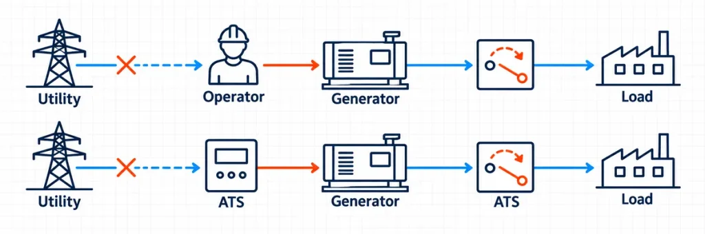
Manual and automatic power-transfer responsibility chains from utility failure through generator supply to the load.This responsibility chain is the best starting point because it avoids two misleading shortcuts. The first is assuming that every portable generator should have a manual switch. Some generators support remote-start arrangements, but the complete generator and transfer system must be designed for them. The second is assuming that every permanent generator needs an ATS. A permanently installed source can still serve a manually controlled system when the operational plan allows it.
A manual switch may move from source I to source II quickly once a person reaches it. The load interruption, however, began when normal power failed—not when the handle started moving. The effective recovery time therefore includes detection, operator response, access to the switch, generator starting, source checks and the mechanical changeover.
An ATS removes most of the human delay, but it does not create uninterrupted power. A utility-to-generator sequence normally includes source-failure confirmation, generator starting, voltage and frequency stabilization, transfer-mechanism operation and contact transition. The load still sees an interruption unless another system, such as a suitable UPS, bridges that interval.
Decision rule: If the load can wait for a competent operator, manual changeover may be sufficient. If the cost or risk begins before that operator can respond, automatic transfer is the stronger starting point.
This distinction matters for refrigeration, pumps, telecom sites, remote infrastructure, data systems and industrial processes. A five-minute response may be acceptable for one workshop and unacceptable for a wastewater pump station. The equipment choice should follow the tolerated outage duration and operating procedure rather than a generic label such as “commercial” or “critical.”
Manual Changeover Works Best When Human Control Is Part of the Plan
A manual changeover switch is often the cleaner solution when backup operation is occasional and supervised. It has no automatic sensing sequence to configure, does not need to issue an engine-start command, and usually has fewer control components to commission and maintain.
That simplicity is valuable only when the human steps are realistic. The operator must be available, trained and able to reach the equipment safely. The site also needs a clear procedure for starting the alternate source, removing or shedding unsuitable loads, checking source condition, transferring, retransferring and shutting down the generator.
Situations that favor manual changeover
- Occasional backup with staff on site: a workshop, small commercial facility or process where a trained person is normally present during operating hours.
- Portable or manually started generator: the source already requires a person to connect, start or supervise it, so automatic switching alone would not complete the recovery sequence.
- Non-critical loads: the delay before restoration does not create an unacceptable safety, product-loss or equipment-risk condition.
- Deliberate load selection: the operator must disconnect nonessential loads before connecting a limited-capacity generator.
- Simple local control: remote monitoring, event logs and unattended generator exercise are not project requirements.
Manual does not mean unprotected or improvised. The device still needs a reliable interlocking arrangement that prevents the normal and alternate sources from being closed together when parallel operation is not permitted. It also needs the correct utilization category, current-carrying capacity, pole configuration and isolation characteristics for the circuit.
The JUTRION JUHGL switch-disconnector range includes load-switching and changeover configurations for industrial distribution. The exact manual changeover arrangement must be selected from the current model data and the project one-line diagram; an ordinary isolator should not be assumed to provide a complete transfer function.
Choose an ATS When Recovery Must Not Depend on Attendance
An ATS combines a power-switching mechanism with sensing and control logic. In a utility-to-generator system, the controller can reject an unacceptable normal source, operate a generator-start contact, wait until the alternate source is within its permitted window, transfer the load, monitor normal-source recovery and later perform retransfer and generator cool-down.
That sequence makes an ATS appropriate when a site is unattended or when waiting for an operator would defeat the purpose of the backup source. Common examples include telecom facilities, remote pumping stations, building services, selected healthcare loads, emergency systems, security infrastructure and production processes with costly restart procedures.
Automation adds interfaces that must be engineered
The ATS controller and generator controller must agree on the start-contact logic. The sensing inputs must match the voltage, frequency, phase arrangement and neutral reference of both sources. Delays need to reject brief disturbances without extending a genuine outage unnecessarily. Position feedback must distinguish a completed transfer from a command that the mechanism did not execute.
This is why “automatic” is not a complete specification. Before choosing a JUTRION ATS, confirm the source arrangement, rated current, poles, neutral treatment, PC- or CB-class architecture, utilization category, controller functions, generator interface and required communication or alarm points. The ATS operating and selection guide explains the complete equipment architecture.
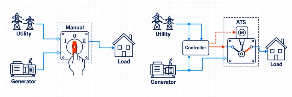
Manual changeover and ATS architectures comparing local handle operation with controller-driven motorized transfer.If an existing ATS does not reach generator position, use the ATS transfer diagnostic sequence to find the first missing state rather than replacing the controller immediately.
Compare Lifecycle Cost, Not Only the Purchase Price
The initial equipment cost of a manual changeover switch is normally lower because it does not include the same sensing, controller, actuator and generator-interface functions. That does not automatically make it the lower-cost system.
If manual restoration requires an operator to travel to a remote site, the operating cost accumulates with every outage and test. If delayed power causes spoiled material, flooding, loss of communications or a lengthy production restart, the consequence can exceed the ATS price difference during one event.
The reverse is also true. Adding automatic controls to a lightly used backup circuit can create unnecessary commissioning and maintenance work. Control fuses, sensing conductors, batteries, actuators, relays, communication modules and generator interfaces all create failure points that a simple manual procedure may avoid.
Manual Changeover vs ATS: Practical Comparison
| Decision factor | Choose manual changeover when… | Choose an ATS when… |
|---|---|---|
| Will someone be present? | A trained operator is reliably available | The site may be empty, remote or difficult to access |
| How long can the load remain off? | Minutes of interruption are acceptable | Recovery must begin immediately after a verified source failure |
| How does the generator start? | Manual start and supervision are expected | The generator supports the required remote-start interface |
| What happens if automation fails? | The manual procedure itself is the normal method | Emergency manual operation and a tested fallback procedure are provided |
| How often will transfer occur? | Outages and exercises are infrequent | Regular exercising, testing or frequent source disturbances justify automation |
| What is the financial consequence of delay? | Low and controlled | Higher than the added lifecycle cost of automation |
| Who will maintain the control system? | The site benefits from fewer control components and a simple local procedure | Qualified staff can test sensing, timing, actuator and generator-start functions |
| Typical best fit | Attended, occasional and delay-tolerant standby applications | Unattended, continuity-sensitive or remote-start applications |
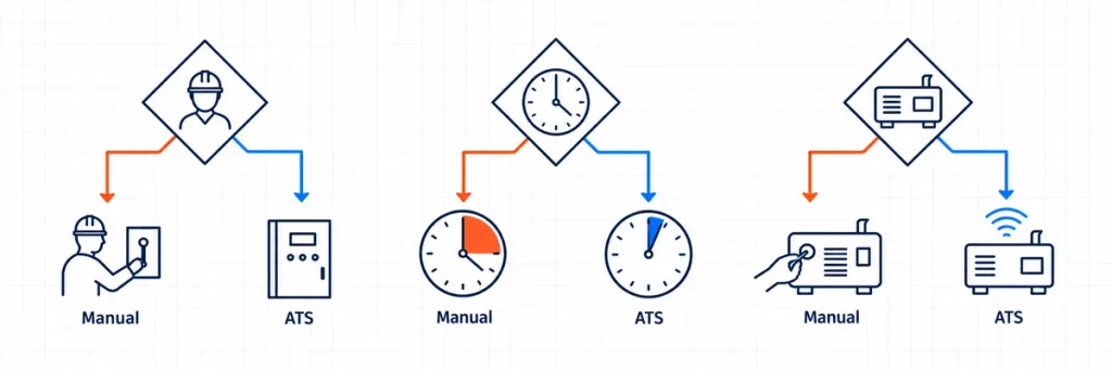
Selection diagram comparing operator presence, acceptable delay and generator-start method for manual changeover and ATS.Evaluate lifecycle cost with the real operating plan: equipment, installation, generator compatibility, commissioning, scheduled testing, travel, spare parts, downtime and training. A purchase-price comparison alone hides the cost of the response method.
Both Options Still Need the Same Electrical Decisions
Changing the operating method does not change the load current or the conductor system. Both manual and automatic equipment must be selected as transfer switching equipment for the actual duty.
IEC 60947-6-1:2026 distinguishes manually operated transfer switching equipment (MTSE), remotely operated equipment (RTSE) and automatic transfer switching equipment (ATSE). These are defined operating methods, not informal grades of the same switch. The standard also places complete-equipment boundaries around the transfer function, so adding a motor or relay to an ordinary switch does not by itself establish compliant ATSE.
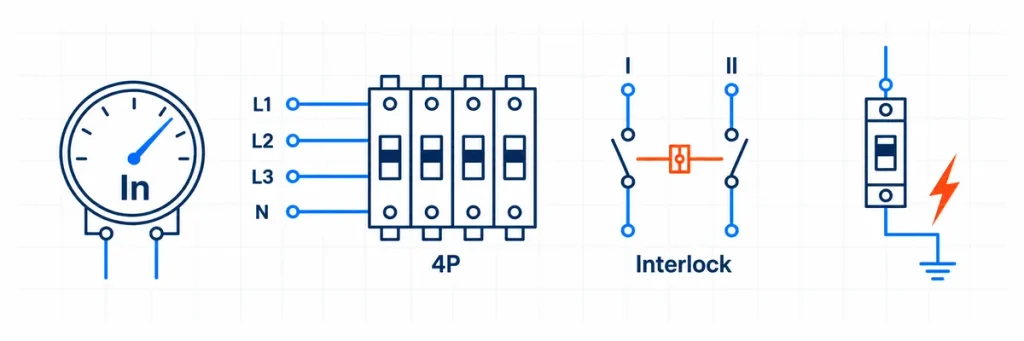
Electrical selection checks for rated current, four-pole conductors, source interlocking and fault coordination.Current and load duty
The switch must carry the highest current expected through the transferred path. Size from the load and system design, not solely from the generator nameplate. Motors, transformers and mixed distribution feeders can impose switching duty and inrush conditions that are not represented by steady-state amperes alone.
For an ATS calculation, the generator kW-to-amps and ATS sizing guide separates transferred load, generator capacity and switch rating. The same current-path reasoning applies to manual changeover equipment.
Poles, neutral and protective earth
A single-phase or three-phase description does not by itself decide whether the neutral must be switched. The source bonding, earthing system, residual-current protection and installation rules determine whether the transfer equipment needs two, three or four switched paths. Protective earth is not treated as an ordinary transferred conductor.
Use the 2P, 3P and 4P transfer-switch guide to define which conductors move. Do not assume that a manual switch and an ATS with the same visible pole count are automatically interchangeable; their terminal functions and approved system arrangements can differ.
Interlocking and transition
For the common open-transition arrangement, the connected load is disconnected from one source before it is connected to the other. Mechanical and/or electrical interlocking helps prevent unintended source overlap. If a project requires closed transition, bypass isolation or more than two sources, it has moved beyond a basic manual-versus-automatic comparison and needs equipment designed for that transfer sequence.
In multi-source systems involving grid-tied solar PV or battery energy storage systems, an open-transition transfer switch must coordinate with the inverter control and protection scheme. Transfer and retransfer delays should allow connected inverters to disconnect, verify the available source and reconnect safely without creating an unintended parallel condition or phase-angle mismatch.
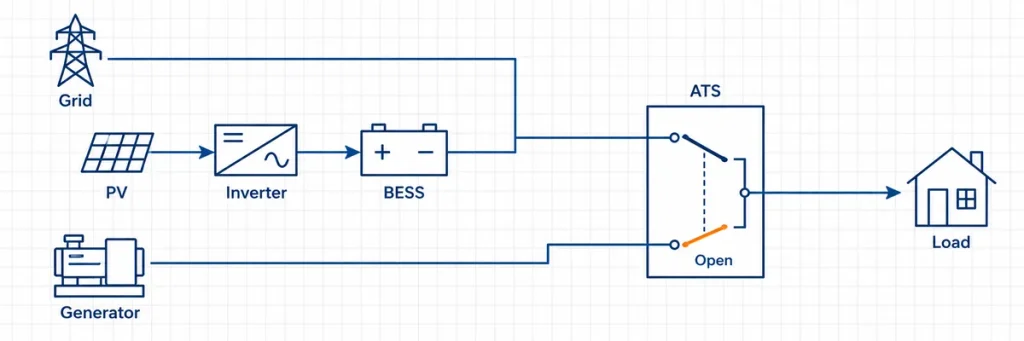
Open-transition ATS coordination between grid, solar PV, battery storage, generator and load.Short-circuit and protection coordination
A transfer switch must be suitable for the available fault conditions and coordinated with upstream protective devices. Automation does not add short-circuit protection automatically, and a manual operating handle does not determine fault performance. Verify the complete equipment marking, class, conditional ratings or withstand data, protective-device relationship and destination-market requirements.
For North American projects, UL Solutions identifies both automatic and nonautomatic transfer switches within its transfer-switch evaluation services under UL 1008 categories. For IEC-oriented projects, use the current IEC 60947-6-1 edition and the documentation for the exact equipment configuration.
Manual mode on an ATS is not a manual transfer switch
Many automatic transfer switches include an emergency handle or a controller mode that accepts a local transfer command. The product remains an ATS: its main contacts, actuator, controller and interlocks still form one approved assembly. Manual operation is a fallback or maintenance function, not permission to ignore source checks or bypass the defined switching sequence.
Three Sites, Three Different Answers
Attended workshop with a portable generator—start with manual changeover. The workshop can stop for several minutes, staff are present during operation, and the generator must be wheeled into position and started manually. An ATS would not eliminate that manual setup and could add controls without producing unattended recovery.
Remote pump station—choose an ATS. The station is normally unattended, and an extended outage can cause an overflow. The generator supports remote start and has a maintained battery system. Automatic sensing begins recovery before personnel arrive; remote alarms and position feedback belong in the operating design.
Attendance alone does not settle the choice. The following cold-storage project shows how the acceptable outage duration, generator interface and financial consequence of delay can change the decision.
Project Example: Cold Storage Facility with a 250 A Main Supply
A cold-storage project used a 400 V, 250 A main distribution circuit supplied by the utility and a 150 kVA standby diesel generator with a remote-start interface. The refrigeration compressors had significant starting demand, while a prolonged outage could lead to temperature alarms and product-loss risk.
A manual changeover arrangement had a lower initial equipment cost, but restoration depended on an operator detecting the outage, reaching the switchboard, starting and checking the generator, and completing the transfer. For this site, the estimated recovery time under the manual procedure was 15–45 minutes, depending on staff availability.
The automatic option used a 250 A open-transition ATS with source monitoring and a generator-start output. After detecting an unacceptable utility supply, the ATS could request generator starting, wait for acceptable voltage and frequency, and then transfer the load. Under the project settings and generator-start conditions, the expected sequence took approximately 5–10 seconds.
The ATS was selected because the cold store was not continuously attended and the cost of a delayed response was greater than the additional control and commissioning cost. Before confirming the equipment, the project still required verification of compressor starting demand, generator voltage dip, staged-load operation, short-circuit coordination, and whether the neutral needed to be switched.
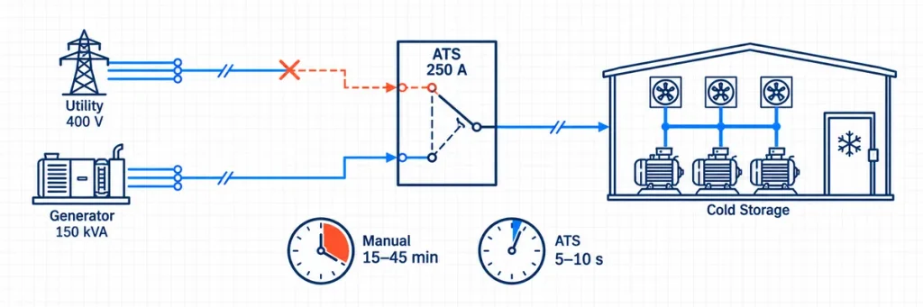
Cold-storage project comparing a 250 A ATS supplied by a 400 V utility and 150 kVA generator with project recovery times.Failure Modes and Commissioning Are Part of the Choice
Manual changeover concentrates risk in the operating procedure. The switch can be electrically healthy while the backup plan still fails because nobody is present, the operator has not been trained, the generator cannot be reached, the wrong loads remain connected or the retransfer sequence is misunderstood. These are operational failures rather than controller failures, but the load experiences the same result: backup power is unavailable when needed.
An ATS moves much of that responsibility into hardware and control logic. This shortens the response, but it introduces different failure paths:
- Incorrect source sensing: a blown sensing fuse, loose neutral, wrong nominal-voltage setting or phase error can make a healthy source appear unavailable—or an unsuitable source appear acceptable.
- Generator interface mismatch: the ATS start contact and generator remote-start input may use incompatible normally open, normally closed, maintained or pulsed logic.
- Control-power failure: a controller, actuator or interposing relay may lose the voltage needed to complete the transfer.
- Mechanical or feedback failure: the controller can issue a valid command while an interlock, mechanism or position contact prevents confirmation of the requested state.
- Setting error: source-acceptance windows, transfer delays, retransfer delays or inhibit inputs can hold the system in a state that appears faulty but follows its configuration.
The design response should match the failure mode. A manual scheme needs a written switching sequence, access control, training and periodic exercises. An automatic scheme needs controller-setting records, generator-interface testing, alarm and feedback verification, emergency manual operation, and maintenance of the generator starting battery and control supply.
Neither arrangement should rely on memory. Keep the approved one-line diagram, operating procedure, source data and equipment model with the panel documentation. If an ATS includes adjustable parameters, record the commissioned values rather than leaving the next technician to infer them from a powered display.
A handle that moves freely does not prove a manual backup plan works, and an ATS test button does not prove the generator can accept the real load. Commissioning should reproduce the intended sequence under controlled conditions and verify each boundary.
For a manual changeover arrangement
- Confirm the switch model, current rating, pole arrangement, terminal identification and permitted operating sequence.
- Verify that the interlock prevents prohibited simultaneous connection of the two sources.
- Perform the approved generator starting and source-readiness checks.
- Transfer the defined load and confirm voltage, phase condition and generator stability.
- Practice retransfer and generator shutdown with the personnel expected to carry out the task.
For an automatic transfer arrangement
- Record normal- and alternate-source sensing values and controller thresholds.
- Simulate loss of the normal source using the manufacturer’s approved test method.
- Confirm the generator-start output, generator availability input, active delays and mechanism command in sequence.
- Verify transfer position, load voltage, feedback contacts, alarms and remote indications.
- Restore the normal source and confirm the stability delay, retransfer, generator cool-down and stop sequence.
- Test emergency manual operation and the recovery procedure for a controller or actuator fault.
Testing live source-transfer equipment can expose personnel to hazardous energy and unexpected generator starting. Commissioning and maintenance should follow the manufacturer instructions, site switching rules and applicable local requirements, and should be carried out by qualified personnel.
Make the Decision in Five Questions
- What is the maximum acceptable interruption? Include detection and human response, not only contact travel time.
- Will a trained operator always be available? Consider nights, weekends, storms, remote access and staff turnover.
- Can the alternate source start and become ready automatically? Confirm the generator interface instead of assuming ATS compatibility.
- What happens if the chosen response is delayed or fails? Translate the answer into safety, process, product-loss and service consequences.
- Does the exact equipment satisfy the electrical system? Confirm current, utilization category, voltage, frequency, poles, neutral, transition, fault coordination, enclosure and applicable documentation.
If questions one to four can reliably be handled by a trained person within the allowed outage window, manual changeover is a defensible and often efficient choice. If they cannot, start with an ATS and engineer the sensing, generator, timing and feedback interfaces as one system. The two options are not simply cheaper and more expensive versions of the same device: they assign the outage decision to different actors.
Define the maximum interruption, attendance plan and alternate-source behavior first. Then match the electrical ratings and complete transfer sequence. JUTRION supplies automatic transfer switch solutions for utility-to-generator and other dual-source applications, together with switch-disconnector options for manually controlled distribution schemes. For model matching, provide the one-line diagram, normal and alternate source data, transferred-load current, pole and neutral arrangement, required operating method and destination market.
Technical References
