

SPD Red Indicator: Has the Surge Protector Failed and When Should You Replace It?
If the local mechanical status window on a conventional pluggable SPD has changed to red, treat that protection module as end-of-life and arrange replacement without delay. The distribution circuit may still be energized, but surge protection on that path is no longer assured. Before removing anything, record which module changed state and distinguish a red cartridge window from a red LED, remote alarm or panel-controller indication. Those signals do not always prove the same fault.
Replace a plug-in cartridge only with the exact compatible type specified for its base. Replace the complete assembly when the base, terminals, coding, remote-contact mechanism or insulation shows damage, or when the manufacturer does not permit cartridge-only replacement. If a new cartridge turns red again, do not keep fitting higher-voltage modules: investigate the continuous voltage, temporary overvoltage exposure, wiring, backup protection and installation conditions first.
A Red Window Is a State Signal, Not a Cause Code
Most modular SPDs contain a thermal disconnector associated with the voltage-limiting component. When ageing, abnormal power-frequency voltage or surge duty causes unsafe heating, the disconnector separates that component from the circuit. The mechanical window then changes state—commonly from green or white to red—to show that the module can no longer be relied upon for surge protection.
The indicator reports the condition of the protective module, not the event that produced it. A red window does not prove that lightning struck the building. It also does not reveal, by itself, whether the cause was accumulated surge stress, a temporary overvoltage, excessive continuous voltage, an incorrect cartridge, poor thermal conditions or another abnormal condition.
Another easy mistake is assuming that a failed SPD must disconnect the load. Many shunt-connected SPDs can reach end of life while normal supply continuity remains unchanged. Machines, lighting and controls may continue operating, but they are now exposed to the next transient. That is why a red window is a maintenance action, even when the panel appears to work normally.
For the wider context—Type 1, Type 2 and Type 3 positions, Uc, Up, In and Imax—see the JUTRION surge protective device guide. This article stays with the narrower field decision: what the red indication proves, what to replace and what to check before returning the panel to service.
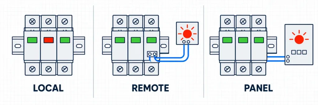
Comparison of a local red SPD window, remote alarm contact and panel controller alarm.First Identify Which Indicator Changed
“The SPD is red” is not yet a complete fault report. A maintenance technician may be looking at the cartridge window, an electronic LED, a remote annunciator or an HMI alarm. Identify the signal source before ordering parts.
| Observed indication | What it normally proves | What it does not prove | Immediate next step |
|---|---|---|---|
| Local mechanical window is red | The monitored protective module has operated its end-of-life disconnection mechanism | The original cause or the condition of every other pole | Record the affected pole; isolate safely; replace the compatible module or assembly |
| Remote alarm operates and a local window is red | The remote circuit is likely reporting an actual module status change | Whether the remote contact and alarm logic are correctly identified | Confirm the local indication, contact state and alarm label before replacement |
| Panel or controller is red while all local module windows remain normal | An alarm circuit has changed state | That the cartridge itself has failed | Check the product manual, auxiliary contact, wiring continuity, supply and controller logic |
| One pole is red | That protection path is unavailable | That the other modules experienced no stress | Record the phase or N–PE position and inspect the coordinated assembly |
| Several poles change together | A shared event or condition is plausible | That all modules failed for exactly the same reason | Preserve the pattern and examine system voltage, neutral condition and event records |
| Replacement turns red again | The installation or operating condition may still be stressing the SPD | That the new cartridge was defective | Stop repeat substitution and diagnose voltage, configuration, wiring and backup protection |
Product-specific conventions take priority over color assumptions. Some monitored systems use more than two states, and some electronic indicators require an auxiliary supply. Check the label and current instruction sheet for the installed model rather than treating every red lamp as a universal cartridge-failure code.
Capture the Failure Pattern Before Removing the Cartridge
A failed cartridge contains useful diagnostic information until it is discarded. A short record can separate a one-time replacement from a recurring site problem.
- Photograph the complete SPD assembly. Include every status window, pole marking, backup protective device and any visible damage.
- Record the failed position. Note L1, L2, L3, N–PE or the protection mode printed on the product.
- Copy the full markings. Manufacturer, series, part number, Type, Uc, Up, In, Imax or Iimp are more useful than “red SPD.”
- Save the time and operating context. Note recent thunderstorms, switching events, generator operation, utility abnormalities, neutral faults or maintenance work.
- Check the remote alarm record. A timestamp from a PLC, BMS or monitoring relay can show whether several panels changed together.
The pattern guides the next measurement. One repeatedly failed phase suggests a local path, simultaneous changes across several boards suggest a shared event, and an N–PE failure calls for closer examination of the assembly and neutral/earth conditions. None proves the cause by itself.
Do not energize a replacement merely to see whether it survives. SPD work belongs inside an enclosure that may contain hazardous energy. Isolation, absence-of-voltage verification, replacement and testing should be performed by qualified personnel under the applicable site procedure and the product instructions.
Measurements That Help—and Tests That Can Mislead
The useful measurements are taken around the SPD and its network, not improvised across a removed MOV cartridge. A handheld resistance reading cannot certify the remaining life of a varistor, and a generic leakage-current limit cannot be applied across different SPD technologies and voltage classes. If the manufacturer provides a dedicated tester or a declared leakage-current test method, follow that method and its product-specific limits.
Disconnect or remove the SPD before an installation insulation-resistance test unless its instructions explicitly state otherwise. A megohmmeter can drive an SPD into conduction, distort the result and, at some test voltages, damage connected protection components. Do not use a 500 V or 1,000 V insulation test as a bench health check for an unknown cartridge.
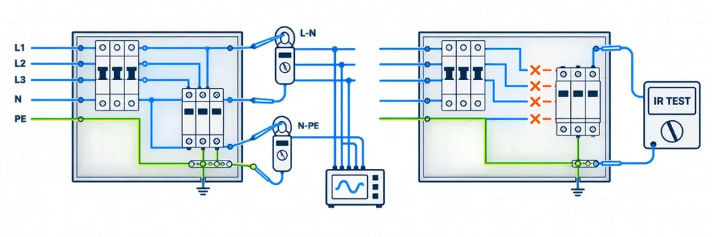
Field voltage measurements around an SPD and isolation before insulation-resistance testing.| Field check | How to take it | What makes the result actionable |
|---|---|---|
| L–N and L–L RMS voltage | Measure every phase and, where recurrence is intermittent, use min/max or a power-quality logger through utility, generator and transfer states | Compare the highest sustained value with the voltage across the actual SPD mode, the declared Uc and the product’s TOV data |
| N–PE voltage | Measure at the affected board and compare it with upstream and nearby boards under representative load | A material, unstable or load-dependent rise calls for neutral and bonding investigation; one universal 5 V, 20 V or 50 V threshold does not fit every earthing system |
| Neutral integrity | Inspect and test the neutral path, terminations and phase balance under the site’s approved safe procedure | Phase-to-neutral voltages moving in opposite directions or changing strongly with load can indicate a loose or open neutral |
| Backup protective device | Record the exact fuse or breaker type, rating and curve together with conductor size and prospective short-circuit current | Pass only when the combination appears in the SPD manufacturer’s coordination data and also protects the connecting conductors |
| Remote contact | Check the local window first, then verify contact state at the SPD and at the PLC or BMS input | This separates a failed module from broken alarm wiring, loss of control power or inverted controller logic |
These checks deliberately avoid universal numbers such as “less than 20 μA means healthy” or “use a 25–63 A fuse.” MOV leakage depends on applied voltage, temperature, waveform and construction, while backup protection differs by SPD Type, short-circuit capability, conductor arrangement and manufacturer. The current datasheet and coordination table are the acceptance criteria.
Replace the Cartridge or the Complete SPD Assembly?
A plug-in design is intended to simplify service, but “it fits the socket” is not a compatibility test. Mechanical coding, protection technology, voltage rating, protection mode, remote signaling and product generation can differ even when two cartridges look similar.
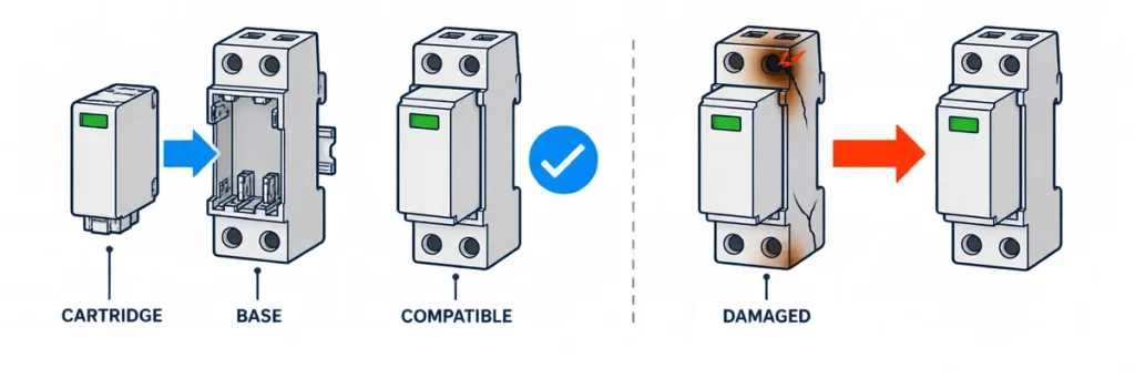
Decision between replacing a compatible SPD cartridge and replacing a damaged complete assembly.Cartridge-Only Replacement Is Appropriate When
- the manufacturer identifies the installed base as reusable;
- the replacement is the exact compatible part or an explicitly approved successor;
- the base, terminals, locking features and insulation show no heat, arc, contamination or mechanical damage;
- the remote contact or status mechanism operates correctly after replacement; and
- the original Type and rating set remain correct for the system.
Replace the Complete Assembly When
- the SPD is a fixed, non-replaceable construction;
- the base or terminal area is discolored, cracked, carbonized, loose or distorted;
- there is evidence of arcing, moisture ingress or damage outside the cartridge;
- the remote signaling mechanism does not reset or its condition cannot be verified;
- the compatible cartridge is obsolete or cannot be positively identified; or
- the installed configuration was wrong for the network and must be redesigned rather than restored.
For a multipole assembly, follow the manufacturer’s replacement policy. Replacing only the red pole may be acceptable for some systems; other maintenance policies replace a coordinated set after a major event or when all modules have similar service exposure. The product documentation and the recorded event should decide—not a universal rule based only on color.
The JUTRION AC and DC SPD range includes modular product families intended to make inspection and cartridge servicing practical. Match the replacement to the exact base and declared protection circuit rather than ordering by pole count or color alone.
Why a New SPD Cartridge Can Turn Red Again
A second red indication soon after replacement changes the job from routine maintenance to failure analysis. Repeated cartridge consumption is evidence that the installation, selection or operating environment may not match the SPD.
| Evidence to collect | Condition it helps distinguish | Engineering response |
|---|---|---|
| Highest steady-state RMS voltage across each actual protection mode | Normal supply versus sustained voltage too close to or above Uc | Correct the supply or select the SPD from verified network and TOV requirements—not by simply choosing the next higher cartridge |
| Voltage events, neutral condition and generator/transfer records | Temporary overvoltage, neutral displacement or source-change disturbance | Correct the system cause and confirm SPD TOV behavior for the earthing arrangement |
| Installed cartridge code and base code | Correct replacement versus an incompatible or incorrectly rated insert | Use the approved module/base combination and protection mode |
| Terminal torque, conductor routing and enclosure temperature | Local heating or installation stress versus electrical overstress | Restore the installation to the specified mechanical and thermal conditions |
| Backup fuse or breaker and prospective short-circuit conditions | Correct disconnection coordination versus unsupported fault duty | Verify manufacturer-declared backup protection and short-circuit capability |
| Event timing across several panels | Localized failure versus a common incoming surge or supply event | Inspect upstream stages, bonding and coordination across the installation |
The continuous operating voltage Uc deserves special attention. Moving from a 275 V cartridge to 320 V or 385 V may reduce stress from an elevated power-frequency voltage, but it may also change the declared voltage protection level Up. A higher Uc is therefore not a heavier-duty cure. The replacement must still provide an effective protection level suitable for the downstream equipment. The separate guide to choosing between 275 V, 320 V and 385 V SPD Uc ratings explains that trade-off in detail.
If the underlying problem is a sustained supply rise or sag rather than a microsecond transient, an SPD is not the device that regulates or disconnects that condition. The over- and under-voltage protector guide explains that protection boundary and the settings used for abnormal mains voltage.
A red module after a storm does not automatically justify a larger Imax. The event may instead have exposed poor bonding, long connecting conductors, missing upstream coordination or an abnormal mains condition.
The Same Red Window Can Mean a Different Investigation
| Application | First evidence to collect | Replacement boundary | Recurrence question |
|---|---|---|---|
| Solar PV combiner box or inverter DC input | String configuration, maximum open-circuit voltage, minimum design temperature, polarity, Ucpv and DC short-circuit current | Use a PV DC SPD with the correct topology and DC disconnection behavior; never fit an AC cartridge as a temporary substitute | Does Ucpv remain above the calculated maximum array voltage? A common IEC design screen is Ucpv ≥ 1.2 × Uoc,max, subject to the applicable design and product instructions |
| Cold store or automated factory board with VFD loads | Bus RMS voltage, min/max record, source-transfer events, neutral condition, switching history and the affected phase | Do not blame VFD harmonics or fit a higher-Uc cartridge from the red window alone | Is the module seeing sustained voltage/TOV stress, repeated switching transients, poor connection geometry or inadequate upstream coordination? |
| Unattended telecom, water or remote utility cabinet | Local status window, remote-contact state, enclosure temperature, supply events and alarm timestamp | Restore protection with the exact compatible spare and test the complete alarm path | Can operations identify the affected panel and dispatch the right cartridge before the next surge event? |
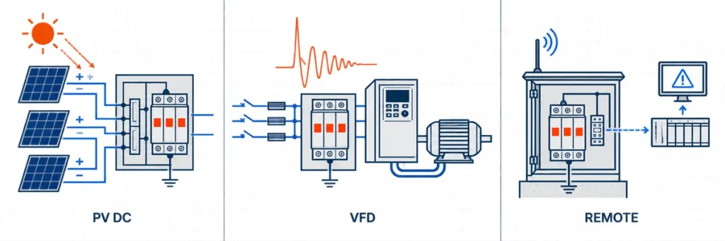
Different SPD red indicator investigations for solar PV, VFD loads and remote cabinets.The solar and industrial cases should not be merged into one generic replacement rule. PV DC systems have no AC current zero and require dedicated DC-rated disconnection and voltage selection. An industrial AC panel, by contrast, may need event logging to distinguish sustained supply stress from switching activity and installation effects.
Close the Job Locally and Remotely
A green window after insertion proves only that the status mechanism has returned to its normal state. Before the maintenance ticket is closed, verify the rest of the protection path.
- Confirm the installed identity. Record the part number, protection Type, Uc, Up and discharge-current ratings.
- Inspect the complete path. Check conductors, terminals, protective earth, backup protection and enclosure condition against the product instructions.
- Verify every status point. Confirm the local windows and, where fitted, the remote contact, PLC, BMS or alarm relay.
- Close the record. Note the date, affected pole, removed and replacement codes, measurements and suspected or confirmed cause.
This record makes a repeat failure comparable with the first. On unattended telecom, solar, cold-storage, water or industrial sites, a volt-free contact can also shorten the time between loss of protection and maintenance response. Commission the complete signal path to the PLC or BMS, including its behavior during loss of control power or a broken wire; the local mechanical window remains the device-level confirmation.
PV installations need a separate spare list because an AC cartridge must not be substituted on the DC side. Array voltage, Ucpv, DC disconnection behavior and protection configuration are covered in the DC SPD selection guide for solar PV systems.
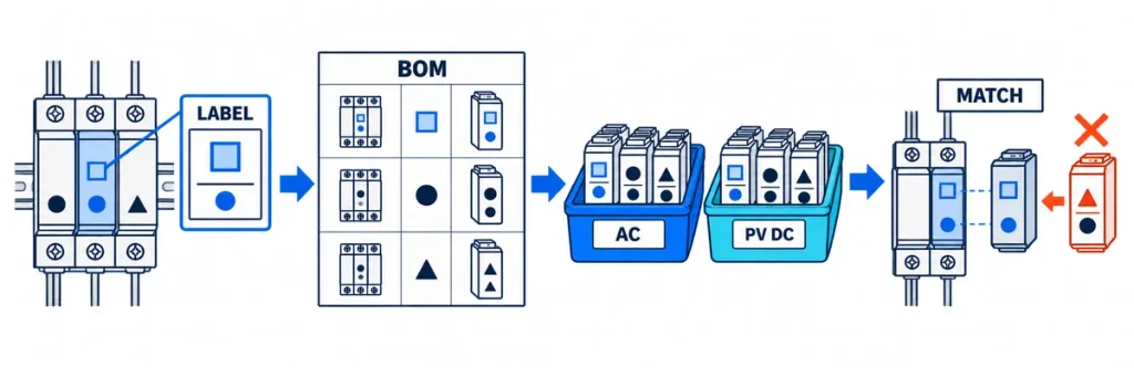
Workflow for recording SPD labels, building a spare cartridge BOM and matching compatible replacements.Build the Spare-Cartridge Kit from the Installed Base
An emergency SPD kit should be a controlled bill of materials, not a box of cartridges grouped only by voltage. For every critical board, record the complete SPD assembly code and the replaceable-module code, protection mode, Type, Uc or Ucpv, remote-contact option and compatible base. Separate AC and PV DC stock physically so that an incorrect emergency substitution is difficult.
| BOM field | Why purchasing and maintenance need it |
|---|---|
| Site, board and protection stage | Identifies where the spare can be used and whether it belongs at the service entrance, sub-board or equipment level |
| Base and cartridge part numbers | Prevents a mechanically similar but electrically incompatible insert from being fitted |
| Protection mode and pole position | Distinguishes L–N, L–PE and N–PE duties and the modules used in 1+1, 3+1 or 4+0 assemblies |
| Type and voltage data | Preserves Type 1, Type 1+2 or Type 2 duty and the approved Uc/Ucpv selection |
| Remote-contact requirement | Keeps the replacement compatible with the existing PLC, BMS or alarm circuit |
| Installed quantity and criticality | Lets the operator set stock from installed population, replacement lead time and acceptable unprotected time rather than a generic percentage |
Panel builders, EPC contractors and distributors can send this BOM together with product-label photographs and the required destination market to JUTRION technical sales. This gives the factory enough information to confirm replacement compatibility, prepare matched spare-cartridge sets and discuss OEM labeling or project quantities without guessing from “1P+N” or “40 kA” alone.
A confirmed red end-of-life window calls for replacement, but the color does not reveal the cause. Restore protection with the exact compatible part. If the base is damaged, replace the assembly; if the indication is remote only, verify the alarm circuit; and if a new cartridge fails again, stop substituting parts and investigate the installation.
Technical References
- IEC 61643-11:2025 — Low-voltage surge protective devices for AC systems: requirements and test methods
- IEC 61643-12:2020 — Selection and application principles for SPDs connected to low-voltage AC systems
- IEC 61643-32:2017 — Selection and application principles for SPDs on the DC side of photovoltaic installations
