Quick Answer: What Are Circuit Breaker Accessories?
According to IEC 60947-2 (the international standard governing low-voltage switchgear and controlgear), a circuit breaker’s primary duty is to safely make, carry, and break currents under normal and specified abnormal conditions. However, a bare breaker operates as an isolated mechanical switch. Circuit breaker accessories are the standardized, modular auxiliary components designed to complement MCCBs, MCBs, and ACBs. While they do not interrupt main faults independently, they are installed internally (such as auxiliary switches and trip units) or externally (such as motor mechanisms and rotary handles) to expand the breaker’s capabilities into four critical dimensions: advanced protection, remote control, status signaling, and mechanical optimization.
The Strategic Value: Simply put, the circuit breaker remains the core mechanical muscle, but the accessories serve as the intelligent nervous system. Today, the moment a fault occurs, the alarm switch instantly transmits a telemetry packet to the control room, while the motor mechanism allows engineers to safely isolate or reset the line remotely. This integration reduced their Mean Time to Repair (MTTR) by 85% and brought the facility into full compliance with modern automated grid infrastructure standards.
Common Circuit Breaker Accessories
Accessory Name
Abbreviation
Function
Shunt Trip
MX
Allows remote tripping via an electrical signal.
Auxiliary Contact
AX / OF
Indicates the ON / OFF status of the breaker.
Alarm Contact
AL / SD
Indicates if the breaker has tripped due to a fault.
Under-Voltage Trip
MN / UVT
Automatically trips the breaker during voltage drops.
Motorized Operating Mechanism
MOM / MO
Enables remote motorized closing and opening.
Front Connection
FC
Standard wiring from the front terminals.
Rear Connection
RC
Wiring from the back to save space inside the panel.
Rotary Handle
–
Allows safer manual switching outside the cabinet door.
Why Are Circuit Breaker Accessories Important?
In modern industrial and commercial infrastructure, a standard circuit breaker provides the foundational “muscle”—the raw mechanical capacity to interrupt an electrical current during a catastrophic fault. However, a bare breaker operates as an isolated component. It is the accessories that provide the “brain” and “nervous system” to the entire electrical installation.
Equipping your circuit breakers with the right accessories is a critical operational necessity for several decisive reasons:
Enhancing Field Personnel Safety: High-power environments inherently carry arc flash risks. Accessories like motor mechanisms and extended rotary handles completely rewrite your on-site safety protocols by enabling operators to switch, reset, or rack out breakers from a safe distance—either outside a locked enclosure door or remotely from a centralized control room.
Minimizing Costly Production Downtime: When a critical production line suddenly halts, every second translates to lost revenue. Without accessories, maintenance teams must manually test lines to deduce why a breaker opened. By utilizing Auxiliary and Alarm Contacts, the breaker instantly transmits precise telemetry to your PLC or SCADA system, differentiating a routine manual turn-off from a severe short-circuit trip in milliseconds.
Proactive Asset Protection against Power Quality Issues: While standard breakers react to overloads, modern machinery (like CNC centers, data servers, and heavy-duty motors) is highly vulnerable to subtler power fluctuations. Under-voltage releases (UVR) act as proactive guardians, tripping the breaker during severe voltage drops (voltage sags) before low voltage can overheat and burn out expensive motor windings.
Ensuring International Compliance & Space Optimization: International standards like IEC 61439 place strict mandates on electrical clearances, segregation, and ingress protection (IP ratings). Structural accessories, such as rear connection kits and terminal shields, allow panel builders to route massive cables efficiently, ensuring full compliance while reducing the physical footprint of the switchboard by up to 35%.
The Bottom Line: Investing in premium circuit breakers but skimping on accessories is like buying a high-performance vehicle without a dashboard or mirrors. Circuit breaker accessories are important because they turn raw electrical protection into operational continuity, predictable maintenance, and absolute peace of mind on-site.
Main Types of Circuit Breaker Accessories
To build a highly automated and compliant low-voltage distribution network, industry standards classify circuit breaker accessories into three primary functional categories based on their physical installation and operational role within the system:
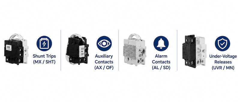
These components are installed inside dedicated internal slots within the circuit breaker housing. They interface directly with the breaker’s internal mechanism to provide telemetry data or execute automated safety trips.
Shunt Trips (MX / SHT):
Enablers of remote emergency isolation. When energized by an external voltage source (such as a fire alarm signal or emergency stop button), the shunt trip instantly forces the breaker’s mechanical latch to open.
Auxiliary Contacts (AX / OF):
Act as the “eyes” of your automation system. They mirror the physical state of the main breaker contacts, sending a real-time “Open” or “Closed” signal to PLCs, SCADA systems, or indicator lights on the panel door.
Alarm Contacts (AL / SD):
These are specialized switches that only actuate when the breaker trips due to an electrical fault (overload, short circuit, or earth fault). They allow maintenance teams to immediately differentiate a hazardous trip from a routine manual shutdown.
Under-Voltage Releases (UVR / MN):
Under-Voltage Releases (UVR / MN): Proactive voltage-quality guardians. They automatically trip the breaker if the incoming line voltage drops below a critical threshold (typically 35% – 70% of rated voltage), protecting downstream motors from burning out during severe voltage sags.
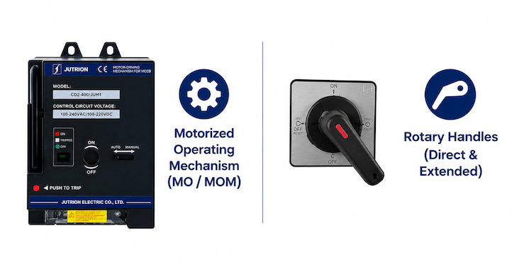
Moving beyond internal components, certain essential accessories are mounted externally onto the front or side of the breaker. These modules fundamentally alter how the device is operated, shifting your system from basic manual toggling to advanced PLC automation or high-safety, through-the-door manual configurations.
Motorized Operating Mechanism(MO / MOM):
These specialized motorized units mount directly to the front of Molded Case Circuit Breakers (MCCBs) to automatically actuate the internal toggle system. By converting remote electrical commands into reliable mechanical force, they integrate seamlessly with Programmable Logic Controllers (PLCs) via RS485 communication protocols (such as Modbus RTU). This is the definitive technology that unlocks automated circuit isolation, remote resetting, and fully centralized grid management directly from the control room.
Rotary Handles (Direct & Extended):
Standard breaker toggles can be stiff and hazardous to operate directly under load. Direct rotary handles offer mechanical advantage for easier flipping, while extended rotary handles use a shaft to allow operators to safely switch the breaker from outside a closed enclosure door, maintaining IP40/IP54 ingress protection.
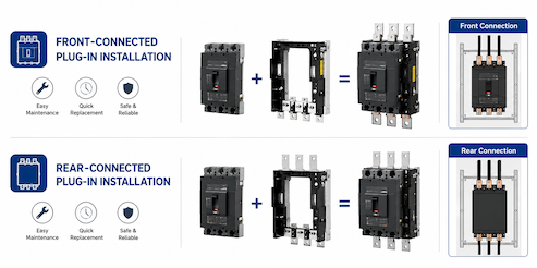
For physical installation, you must also consider how the circuit breaker connects to the switchboard structure. Plug-in circuit breakers can be configured with front-connected or rear-connected bases according to the cabinet layout, wiring direction, and maintenance requirements. Both configurations allow the breaker to be removed and replaced without disconnecting the main circuit conductors from the base.
Front-Connected Plug-In Installation
A front-connected plug-in circuit breaker is mounted on a dedicated plug-in base, with the main circuit cables or busbars connected to the front terminals of the base. The breaker can be removed and replaced without disconnecting the main conductors, helping simplify maintenance and reduce replacement time.
Rear-Connected Plug-In Installation
A rear-connected plug-in circuit breaker is also mounted on a dedicated plug-in base, but the main circuit is connected from behind the mounting plate through rear terminals or connecting bars. This arrangement provides the same convenient replacement function while keeping the front cabinet layout cleaner and reducing interference with front-side wiring.
Both configurations support faster breaker replacement. The main difference lies in whether the main circuit is connected to the front or rear terminals of the plug-in base.
How to Select the Right Circuit Breaker Accessories
In real low-voltage electrical projects, we often see the same challenge among panel builders, system integrators, and project engineers. They know that MCCBs, MCBs, or ACBs may need accessories to support remote control, status indication, fault alarm, or door-mounted operation, but they are often unsure how to choose the correct accessory configuration.
Relying only on complex product manuals without confirming the actual cabinet structure and control requirements can lead to costly installation problems. For example, selecting the wrong control voltage for a shunt trip may damage the coil, confusing an auxiliary contact with an alarm contact may cause incorrect status feedback, and ignoring terminal layout or installation space may affect wiring, electrical clearance, and future maintenance.
That is why circuit breaker accessories should not be selected by name alone. The correct selection should consider the breaker model, frame size, control voltage, installation method, signal requirement, and actual application environment.
To streamline this complex process and safeguard your engineering investment, I have mapped out the core selection criteria into practical, decisive steps. Let’s dive into how you can precisely configure the ideal accessory layout for your next deployment.
Step 1: Confirm the Circuit Breaker Type, Model, and Frame Size
The first step is to identify the exact circuit breaker platform on which the accessory will be installed. Circuit breaker accessories are generally not universal. Even when two circuit breakers have the same rated current, differences in product series, frame size, pole configuration, internal operating mechanism, and mounting dimensions may make their accessories incompatible. Before selecting any accessory, confirm the following information:
Circuit breaker type: MCB, MCCB, or ACB
Manufacturer and product series
Complete circuit breaker model
Number of poles: 1P, 2P, 3P, or 4P
Frame size, such as 100A, 250A, or 400A For example, a shunt trip designed for a 100AF MCCB may not fit a 250AF breaker, even if both circuit breakers operate at the same rated current. Their mechanical dimensions, mounting clips, operating stroke, and terminal positions may be completely different. Therefore, the circuit breaker model and frame size should always be checked against the accessory compatibility table provided by the manufacturer.
Practical Tip: Do not select an accessory based only on the breaker’s rated current. Always provide the complete model number or a clear photo of the breaker nameplate when requesting a quotation.
Step 2: Match the Accessory to the Required Application
After confirming the circuit breaker model, the next step is not simply to choose an accessory by name, but to identify the actual control, protection, or signalling requirement of the electrical system. Different accessories may be used together, but each one is designed to solve a specific application requirement. The correct selection should therefore begin with the question: What does the system need the circuit breaker to do?
In my years of heading industrial engineering projects, I have seen teams bypass this critical step and pick accessories blindly from a catalog based on names alone. This always leads to chaos during commissioning—such as confusing an auxiliary contact with an alarm contact, which leaves the central PLC completely blind to whether a trip was a safety fault or just a manual operation.
TO AVOID THESE COSTLY FIELD ERRORS, LET’S LOOK AT HOW SPECIFIC SYSTEM REQUIREMENTS DICTATE YOUR COMPONENT SELECTION
If the breaker must be tripped remotely by a fire alarm system or emergency stop circuit, a shunt trip is normally required.
If the breaker must open or prevent closing when the control voltage drops below a specified level, an undervoltage release is more suitable.
If the control system needs to know whether the breaker is ON or OFF, an auxiliary contact should be selected.
If the system needs to distinguish a protection trip from a manual opening operation, an alarm contact is required.
If the breaker must be opened or closed remotely, a motor operator may be required.
If the breaker must be operated from outside the cabinet door, a rotary handle should be selected.
If the breaker needs to be removed or replaced quickly without disconnecting all main cables or busbars, a plug-in configuration may be more suitable.
The accessory should be selected according to the required function rather than its appearance or general product name.
Step 3: Match the Control Voltage and Power Supply Type
Control voltage is one of the most important parameters when selecting electrically operated accessories. Shunt trips, undervoltage releases, closing coils, and motor operators are designed for specific voltage ranges.
Common control voltages include:
AC 24V, 36V, 48V, 110V, 220V, 230V, or 380V
DC 24V, 36V, 48V, 110V, 125V, or 220V
The selected accessory must match both the voltage level and the power supply type.For example, a 220V AC shunt trip should not be connected to a 220V DC control circuit,Although the voltage value is the same, the coil structure and electrical characteristics are different,An incorrect power supply may cause failure to operate, excessive heating, coil damage, or unreliable tripping.
Before confirming the accessory, check the following:
Whether the control supply is AC or DC
The nominal control voltage
The permissible operating voltage range
Whether the signal is continuous or momentary
Whether the accessory remains energized during normal operation
Important: Undervoltage releases are usually continuously energized while the circuit breaker is operating. Therefore, the control circuit must provide a stable power supply and sufficient coil capacity.
Motor Operator Power Supply: The motor operator should normally be powered from the line side of the circuit breaker or from an independent control power supply. If it is powered from the load side, it may lose power after the breaker opens or trips, preventing subsequent remote closing or reset operation.
Customization: The control voltage of the motor operator can be customized according to the customer’s power supply and project requirements.
Step 4: Check the Accessory Installation Position and Compatibility
Many MCBs and MCCBs have designated installation positions or slots for internal accessories. The number, position, and compatible accessory combinations may vary depending on the product series, frame size, and pole configuration.
Before ordering, confirm the following:
Whether the accessory is installed internally or externally
Whether it is mounted on the left side or right side
Whether one slot can accept more than one contact module
Whether the selected accessories can be installed together
Whether additional terminal blocks or wiring leads are required
Some MCCBs, especially residual current MCCBs, have limited internal space for accessories. In certain models, only one internal accessory position is available, so a standard shunt trip and a separate auxiliary contact cannot be installed independently at the same time.In this situation, an integrated shunt trip and auxiliary contact module may be selected when both remote tripping and breaker position feedback are required.The accessory mounting arrangement may also vary between different MCCB series. For example, the shunt trip may be installed on the left side in one model but on the right side in another, while the auxiliary contact or alarm contact may occupy a different designated position.
Therefore, accessory compatibility cannot be determined only by the accessory name or breaker rated current. The exact MCCB series, frame size, residual current protection function, pole configuration, and internal accessory layout must be confirmed before ordering.
Practical Tip: If the MCCB has only one available accessory slot, confirm whether an integrated accessory module, such as a shunt trip with an auxiliary contact, is available for that breaker series.
Selecting the correct circuit breaker accessories requires more than identifying the accessory name. The breaker model, frame size, required function, control voltage, installation position, and accessory compatibility must all be confirmed together. A correct configuration should meet both the electrical control requirements and the actual cabinet installation conditions.
Step 5: Plug-In Circuit Breaker Installation and Connection Options
In addition to electrical functions, the installation and connection method of the circuit breaker can also affect accessory selection. Different plug-in configurations may require different bases, terminals, mounting arrangements, and cabinet structures.
Front-Connected Plug-In Installation:
A front-connected plug-in circuit breaker is mounted on a dedicated plug-in base, with the main circuit cables or busbars connected from the front. The breaker can be removed and replaced without disconnecting the main circuit conductors from the base, helping reduce maintenance time.
Rear-Connected Plug-In Installation:
A rear-connected plug-in circuit breaker is also mounted on a dedicated plug-in base, but the main circuit is connected from behind the mounting plate through rear terminals or connecting bars. It provides the same convenient replacement function while supporting a cleaner front cabinet layout.
Both configurations support faster breaker replacement. The main difference is the direction of the main circuit connection and the corresponding cabinet layout requirements.
Circuit Breaker Accessory Selection Checklist
Selection Item
What to Confirm
Circuit breaker type
MCB, MCCB, residual current MCCB, or ACB
Manufacturer and series
Complete product series
Complete model
Full circuit breaker model number
Frame size
100AF, 250AF, 400AF, etc.
Number of poles
1P, 2P, 3P, or 4P
Required function
Remote trip, undervoltage protection, status feedback, fault alarm, remote operation, or interlocking
Control voltage
Rated voltage and AC/DC supply type
Operating signal
Continuous or momentary
Accessory position
Internal, external, left side, or right side
Accessory combination
Separate accessory or integrated module
Connection method
Front connection or rear connection
Installation method
Fixed-mounted or plug-in
Cabinet conditions
Depth, wiring space, shaft length, and maintenance clearance
Project documents
Nameplate photo, control schematic, cabinet drawing, and technical requirements
If any of the above information is uncertain, provide the complete breaker model, nameplate photo, and project drawings to the supplier before placing the order.
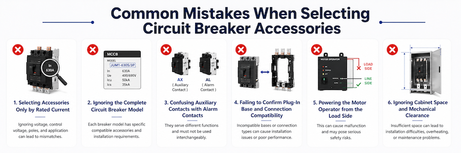
Common Mistakes When Selecting Circuit Breaker Accessories
Even experienced panel builders and project engineers can make accessory selection mistakes when the breaker model, control voltage, installation structure, or signal requirements are not fully confirmed. The following are some of the most common problems found in circuit breaker accessory selection.
1.Selecting Accessories Only by Rated Current
Circuit breaker accessories should not be selected only according to the rated current of the breaker. Two breakers with the same rated current may belong to different product series or frame sizes, and their internal structures, mounting dimensions, and accessory positions may be completely different.
How to avoid it: Always confirm the complete breaker model, product series, frame size, and number of poles.
2. Ignoring the Complete Circuit Breaker Model
Providing only information such as “250A MCCB” is usually not enough to identify the correct accessory. The complete model number may include important information about the breaker series, frame size, breaking capacity, pole configuration, and protection type.
This is especially important for residual current MCCBs, electronic MCCBs, and breakers with special internal structures.
How to avoid it: Provide the complete model number or a clear photo of the breaker nameplate.
3. Confusing Auxiliary Contacts with Alarm Contacts
Auxiliary contacts and alarm contacts both provide electrical feedback signals, but they indicate different conditions.An auxiliary contact normally indicates whether the circuit breaker is ON or OFF. An alarm contact indicates whether the breaker has tripped because of overload, short circuit, or another protection event.If the wrong contact is selected, the PLC or monitoring system may receive incorrect status information.
How to avoid it: Confirm whether the system requires position feedback or fault-trip feedback.
4.Failing to Confirm Plug-In Base and Connection Compatibility
A plug-in base must match the exact breaker series, frame size, number of poles, and connection method.Front-connected and rear-connected plug-in configurations may use different bases, terminals, connecting bars, and cabinet structures.A base selected only by rated current may not fit the breaker correctly.
How to avoid it: Confirm whether the system requires a front-connected or rear-connected plug-in configuration before ordering.
5.Powering the Motor Operator from the Load Side
If the motor operator is powered from the load side of the circuit breaker, it may lose power after the breaker opens or trips.This may prevent the breaker from being remotely closed or reset.
How to avoid it: The motor operator should normally be powered from the line side of the breaker or from an independent control power source, according to the system design.
6.Ignoring Cabinet Space and Mechanical Clearance
Even if the accessory is electrically compatible, it may still be impossible to install if the cabinet space is insufficient.Motor operators, rotary handles, plug-in bases, rear terminals, terminal covers, and cable lugs all require additional installation space.Insufficient clearance may affect wiring, cabinet door closing, operation, and future maintenance.
How to avoid it: Check the cabinet drawing, breaker dimensions, accessory dimensions, cable routing, and maintenance space before confirming the order.
Most circuit breaker accessory selection errors can be avoided by confirming the complete breaker model, control voltage, required function, internal accessory layout, installation method, and cabinet conditions before ordering.
When the accessory configuration is uncertain, provide the supplier with the breaker nameplate photo, control schematic, and cabinet drawing for compatibility verification.
Frequently Asked Questions About Circuit Breaker Accessories
Can I use JUTRION accessories as high-quality replacements or upgrades for major breaker brands?
Absolutely. At JUTRION, our complete range of internal and external accessories is custom-engineered and precision-molded to strictly match the mechanical linkage profiles and electrical specifications of standard low-voltage circuit breakers in the global market. As long as you select the verified cross-reference model from our catalog, our components deliver identical mechanical endurance and seamless integration, offering engineering teams a highly cost-effective alternative with significantly faster production lead times.
Are Circuit Breaker Accessories Universal?
No. Circuit breaker accessories are generally designed for specific product series, frame sizes, pole configurations, and internal mechanisms. Even if two circuit breakers have the same rated current, their accessories may not be interchangeable. Always confirm the complete breaker model and accessory compatibility before ordering.
What Is the Difference Between an Auxiliary Contact and an Alarm Contact?
An auxiliary contact indicates the operating position of the circuit breaker, such as ON or OFF. An alarm contact indicates that the breaker has tripped because of an overload, short circuit, earth fault, or another protection event. An auxiliary contact is used for position feedback, while an alarm contact is used for fault-trip indication.
Can I install a Shunt Trip and an Under-Voltage Release into the same breaker simultaneously?
This strictly depends on the breaker’s frame size and its internal cavity layout. In compact, lower-current devices (such as 125A frames), there is often only one physical internal slot designated for voltage-tripping coils, meaning you must choose between a shunt trip or a UVR. However, in larger frame sizes (such as 400A or 800A), multiple independent slots are typically engineered, allowing you to combine both internal accessories flawlessly. When configuring your project, our JUTRION engineering team can provide you with a precise combination layout based on your housing limits.
What is the main operational difference between a Shunt Trip and an Under-Voltage Release (UVR)?
The core difference lies in their activation logic. A Shunt Trip requires an active electrical pulse (applying voltage to the coil) to mechanically trip the breaker remotely, making it perfect for fire alarm linkages. Conversely, an Under-Voltage Release (UVR) keeps the breaker closed as long as standard grid voltage is present; it trips the breaker automatically when the control voltage drops below a safe threshold (typically between 35 percent and 70 percent of rated voltage) or completely fails. This makes the UVR ideal for protecting downstream motors from sudden grid brownouts.
How does JUTRION ensure the long-term reliability and mechanical endurance of its internal accessories over thousands of operating cycles?
Field failure is not an option when safety is on the line. At JUTRION, we treat our accessories not just as molded plastic and copper, but as the precision neural network of your power distribution system. Every batch of our shunt trips, auxiliary contacts, and motor operators undergoes rigorous, automated fatigue and dielectric testing in our compliance labs. We simulate harsh industrial environments, ensuring our micro-switches and heavy-duty coils sustain mechanical and electrical endurance ratings that fully comply with IEC standards. By engineering our components with high-grade, heat-resistant polymers and premium silver-alloy contacts, JUTRION guarantees stable signal feedback and instant remote actuation even after years of demanding operational cycles.
Circuit breaker designs vary significantly across global brands. Can JUTRION truly guarantee physical compatibility across different manufacturers?
Yes, we can. This universal adaptation capability is exactly why international clients partner with us. Over the years, JUTRION has built and continuously updated an extensive engineering database and precision matrix mold library. Today, our highly versatile internal and external accessories can seamlessly adapt to over 99 percent of low-voltage molded case circuit breakers (MCCBs) and miniature circuit breakers (MCBs) available on the global market. Whether your switchboard relies on standard European designs, traditional Asian form factors, or major mainstream multi-national brands, our engineering team can instantly match you with the precise JUTRION accessory variant designed to fit that exact internal housing and mechanical linkage profile.
Need Help Selecting Compatible Circuit Breaker Accessories?
Choosing the correct circuit breaker accessory requires more than matching the accessory name. The breaker model, frame size, control voltage, installation position, connection method, and project requirements must all be verified together.
Provide JUTRION with the following information: Complete circuit breaker model or nameplate photo Required accessory function Control voltage and AC/DC power supply type Installation method and project quantity
Our engineering team will verify accessory compatibility and recommend a suitable configuration for your electrical project.
Electrical Engineer | Low-Voltage Power Distribution
Hello, I’m Evan.
I am an electrical engineer with 10 years of experience in low-voltage electrical equipment, circuit protection, and power distribution systems. I specialize in product selection, application engineering, and technical support for industrial, commercial, and renewable-energy projects.
For technical inquiries, please contact me at evan@jutrion.com.