

Arc Fault Detection Device: How It Works and How to Choose
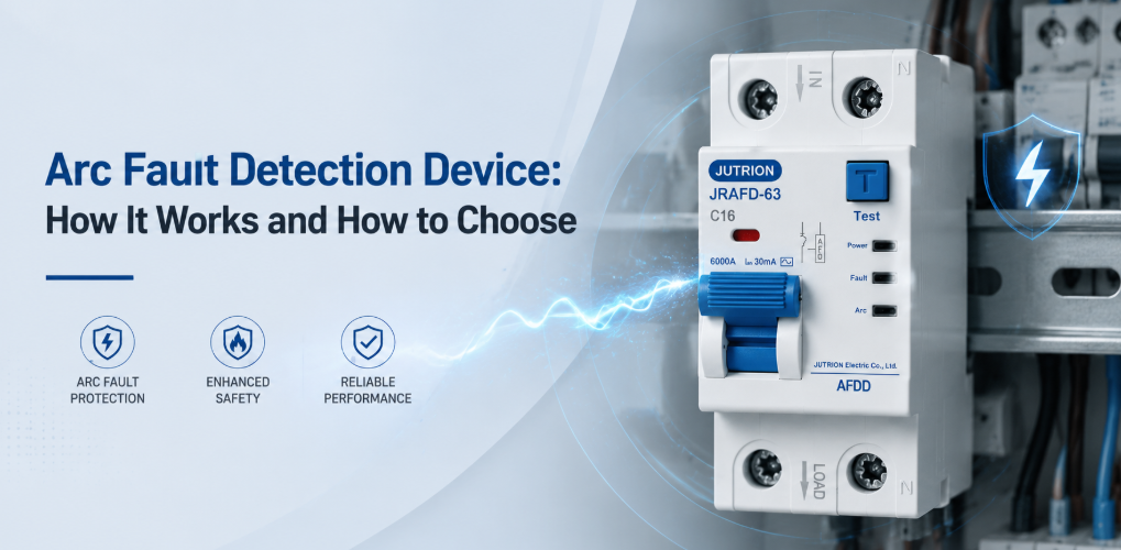
JUTRION Arc Fault Detection Device AFDD for arc fault protection and electrical safety“16 A AFDD” is not a complete specification. It does not tell a supplier which arc-fault product standard applies, whether overload and residual-current protection must be integrated, what short-circuit capacity is required, how the neutral is handled, or whether the device is approved for the intended distribution board. Those omissions can turn a valid fire-protection concept into an incompatible bill of materials.
The practical selection rule is to work from the final circuit outward. First confirm whether the installation code requires or recommends arc-fault protection for that circuit. Then select the protection architecture, coordinate every electrical rating, and match the device to the distribution board. An arc fault detection device (AFDD) adds protection against hazardous series and parallel arcs; it does not automatically replace an MCB, RCD, RCBO, SPD, or sound wiring practice.
Key Takeaways
- AFDDs detect dangerous series and parallel arc patterns that may not produce enough overcurrent or earth leakage to operate a conventional MCB or RCD.
- An AFDD complements other protective devices rather than replacing them. Overload, short-circuit, residual-current, and surge protection must still be provided where required.
- Product and installation standards answer different questions. IEC 62606 covers AFDD product requirements, while national wiring rules determine where protection is required or recommended.
- The protection architecture affects the whole circuit design. Standalone AFDD, AFDD-MCB, AFDD-RCBO, and approved modular combinations provide different sets of functions.
- Rated current alone is not enough for selection. Voltage, frequency, poles, curve, breaking capacity, RCD type, busbar, terminals, module width, and enclosure conditions must also match.
- Correct installation and testing are essential. Neutral routing, terminal torque, thermal conditions, test procedures, and trip-cause indication all affect reliable operation and fault finding.
Use the following seven points to compare AFDD options for a specific circuit and target market.
| Decision | Question to answer | Why it changes the selection |
|---|---|---|
| Regulatory scope | Which country, code edition, occupancy, circuit type, and rated current apply? | AFDD requirements are not universal and can change by national adoption. |
| Product system | Is the project IEC AFDD, UK BS EN AFDD, or North American AFCI? | The standards, ratings, certification, panel interfaces, and terminology differ. |
| Protection architecture | Is arc detection standalone, combined with an MCB, or combined with an RCBO? | The choice determines which additional protective devices remain necessary. |
| Electrical ratings | What voltage, frequency, current, curve, residual-current type, and breaking capacity are required? | Each value corresponds to a different operating or fault condition. |
| Assembly interface | Which board, busbar, poles, neutral arrangement, module width, and accessories apply? | Mechanical fit alone does not establish electrical or certification compatibility. |
| Operational consequences | What happens if the circuit trips, and how will the cause be identified? | Continuity, selectivity, indication, and maintenance access affect the design. |
| Product support | Which data sheets, instructions, certificates, samples, and customization services will help the project? | Clear documentation makes comparison, installation, approval, and repeat ordering easier. |
This order helps buyers compare equivalent products and communicate their requirements efficiently. It also separates decisions that are often confused. For example, a C tripping curve describes an overcurrent function; it does not describe arc sensitivity. A 30 mA marking describes residual-current protection; it does not prove that the device includes AFDD functionality.
What Is an Electrical Arc, and Why Can It Start a Fire?
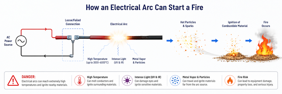
An electrical arc is a sustained discharge of current through an ionized gap between conductive points. In a healthy switch, a very brief arc can occur when contacts open and is normally contained by the device. A fault arc is different: it develops unintentionally at damaged insulation, a broken conductor, or a poor connection and can repeatedly release intense heat into nearby material.
An AFDD is valuable because some dangerous arcs remain below the operating threshold of conventional protective devices. A series arc can occur at a loose terminal, a partially broken conductor, or a damaged plug contact. The load remains in series with the fault, so a 6 A load can continue drawing approximately its normal current while intense heating develops at a tiny contact area. A 16 A miniature circuit breaker (MCB) has no overload reason to trip, and an RCD may see no imbalance if the current returns through neutral.
A parallel arc crosses between conductors at different potentials. It can follow insulation damaged by a fastener, crushing, moisture, ultraviolet exposure, pests, or thermal aging. The arc path may limit and interrupt the current, preventing a conventional breaker from seeing a stable metallic short circuit. A line-to-earth arc may operate an RCD, but a line-to-neutral arc can remain balanced from the RCD’s perspective.
Common warning conditions include loose socket terminals, worn plug contacts, cables trapped behind furniture, conductors damaged during stripping, flexible cords repeatedly bent near an appliance, and insulation penetrated by screws or nails. Some faults begin as a high-resistance connection that heats and oxidizes before intermittent arcing appears. Others develop along a carbonized insulation path after the original damage. These mechanisms explain why correct torque, careful cable routing, suitable accessories, and periodic inspection remain important even when AFDD protection is installed.
Normal equipment can also produce electrical signatures that resemble parts of an arc waveform. Switch contacts, relays, dimmers, brushed motors, and switched-mode power supplies are familiar examples. A compliant AFDD uses several signal characteristics and their duration rather than reacting to every spark or high-frequency disturbance. This discrimination supports normal operation while allowing the device to respond when a hazardous pattern meets its trip criteria.
The AFDD continuously analyzes electrical characteristics such as burst duration, irregularity, high-frequency components, current discontinuity, and behavior around the AC zero crossing. Its algorithm must distinguish hazardous patterns from normal switching arcs, relay operation, dimmers, brushed motors, and electronic power supplies. Once the defined criteria are satisfied, it commands an opening mechanism to disconnect the circuit.
This working principle leads to three selection boundaries:
- An AFDD is not simply a more sensitive MCB. Current magnitude and arc-pattern recognition are different protection principles.
- An AFDD is not an RCD. An earth-leakage threshold such as 30 mA does not describe arc detection.
- An AFDD cannot compensate for an underrated conductor, inadequate short-circuit capacity, a wrong RCD type, or a poor terminal.
In practice, I first map the required protection functions in a matrix: overload, short circuit, residual current, arc fault, and transient overvoltage. Each required function must be assigned to a suitable device or integrated product. This exposes missing protection and avoids paying twice for a function without understanding the coordination.
| Device/function | Main condition detected | What it does not generally replace |
|---|---|---|
| MCB or fuse | Overload and short-circuit overcurrent | Residual-current or arc-pattern detection |
| RCCB/RCD | Residual-current imbalance | Overcurrent protection unless specifically integrated |
| RCBO | Overcurrent plus residual current | Arc detection unless the product is explicitly an AFDD-RCBO |
| AFDD | Defined hazardous arc signatures | Other functions not stated on the product certificate |
| SPD | Transient overvoltage limitation | Overcurrent, residual-current, or arc-fault protection |
Confirm Where the Rule Applies Before Selecting a Rating
Product conformity and installation compliance answer different questions. A product standard tells a manufacturer how an AFDD is constructed and tested. An installation standard tells a designer where protective measures are required or recommended. National legislation and the authority having jurisdiction determine which edition is enforceable.
IEC Projects: Use the Product and Installation Standards Together
IEC 62606:2013+A1:2017+A2:2022, consolidated edition 1.2, applies to arc fault detection and protection devices for household and similar uses in AC circuits. It recognizes a device with opening means used with declared protection, a product integrating another protective device, and a separate arc-detection unit assembled with a declared protective device. This scope defines the product family; it does not by itself decide every location where an AFDD must be installed.
The installation context is found in standards such as IEC 60364-4-42:2024, which addresses protection against thermal effects. Its 2024 revision reorganized and expanded requirements for locations where fire consequences are severe. National standards based on IEC 60364 may adopt these provisions at different times or with modifications. Therefore, “IEC country” is not a sufficient compliance statement.
Record the destination country, the exact national standard and edition, the occupancy classification, whether the circuit supplies socket outlets or fixed equipment, its rating, and any exceptions. If the product is intended for several markets, create a market matrix rather than one global claim.
United Kingdom: Control the Edition Transition
UK specifications must identify the current BS 7671 position. The IET edition checker states that BS 7671:2018+A4:2026 has been published and that Amendment 3:2024 remains valid until 15 October 2026. A project designed during this transition should state which edition forms the contractual basis rather than mixing text from A2, A3, and A4 web articles.
Do not copy a list of “mandatory buildings” from an undated installer blog. Check the current regulation, definitions, circuit scope, exceptions, and project requirements. Client standards, insurers, fire strategies, or a documented risk assessment may also justify protection beyond the minimum national rule.
North America: Specify AFCI, Not a Generic IEC AFDD
In the United States and Canada, the usual term is arc-fault circuit interrupter (AFCI). UL Solutions identifies UL 1699 for US AFCI evaluation and CSA C22.2 No. 270 for Canada. North American products include circuit-breaker and receptacle forms with defined application categories.
An IEC 62606 DIN-rail AFDD and a UL-listed AFCI are not interchangeable merely because both respond to arcs. Voltage, frequency, circuit rating, panelboard listing, neutral connection, test program, and installation code differ. For US work, also verify the locally adopted NEC edition and amendments. For replacement breakers, the UL marking and application guidance emphasizes product identification, instructions, and compatibility with the applicable panelboard.
Choose the Protection Architecture Before Comparing AFDD Models
IEC 62606 allows several construction approaches, but catalogues may describe them differently. The engineering question is which functions are inside the selected product and which must be provided by declared associated devices.
| Architecture | Functions typically present | Best-fit consideration | Main verification risk |
|---|---|---|---|
| AFDD with opening means | Arc detection and circuit opening | Projects using a separately declared overcurrent or residual-current device | Assuming it has MCB or RCD protection when it does not |
| AFDD integrated with MCB | Arc, overload, and short-circuit protection | Circuits where residual-current protection is separate or not required | Omitting required RCD protection or using an unsuitable shared RCD |
| AFDD integrated with RCBO | Arc, overload, short circuit, and residual current | Individual final-circuit protection and clearer fault separation | Treating all RCBO details as standard when type, sensitivity, curve, and poles vary |
| AFD unit plus declared protective device | Depends on the approved combination | Manufacturer systems designed for field assembly | Combining visually compatible modules that were never evaluated together |
An AFDD-RCBO is often the clearest architecture for a final circuit requiring both additional residual-current protection and arc-fault mitigation. It adds arc detection to the overload, short-circuit, and residual-current functions associated with an RCBO. This arrangement limits a residual-current or arc trip to one circuit and reduces interconnections. The residual-current type must still suit the loads, the MCB curve must coordinate with fault conditions and inrush, and the device must be compatible with the board.
A shared upstream RCCB with several AFDD-MCB final circuits may reduce device cost, but one residual-current event can disconnect multiple circuits. Leakage from several electronic loads can accumulate, and diagnosis becomes less direct. The designer must consider unwanted loss of service, selectivity, permissible earth leakage, and any rule requiring individual protection.
Separate modules provide flexibility when the manufacturer declares the combination. Similar width, matching color, or a common DIN rail does not by itself confirm short-circuit coordination, trip coupling, or terminal temperature performance. Sharing the existing board and protection details with the manufacturer makes it easier to identify a suitable combination.
Where AFDD Protection Provides the Most Value
AFDDs are primarily used on final circuits where damaged cables or loose electrical connections may generate dangerous arc faults that conventional overcurrent or residual-current protection cannot detect. The need for AFDD protection depends on both the likelihood of cable damage and the potential consequences of a fire.
Bedrooms and Buildings with Sleeping Accommodation
- Bedrooms, hotels, care homes, student residences, hostels, and similar sleeping environments are among the most common applications for AFDDs. Because occupants may not notice the smell, sound, or early signs of an electrical fault while asleep, AFDDs provide an additional layer of protection by detecting arc faults caused by loose connections, damaged wiring, or deteriorated appliance cords.
The exact circuits requiring AFDD protection depend on local electrical regulations and installation standards. Designers should also consider power continuity for emergency systems, alarms, and other safety-related equipment.
Timber Buildings and Combustible Environments
- Timber-frame buildings, woodworking workshops, barns, storage facilities, and other locations containing combustible materials present a higher fire risk if an electrical arc occurs. AFDDs can help reduce this risk by interrupting developing arc faults before they become an ignition source.
AFDD protection should always complement—not replace—proper cable installation, overcurrent protection, enclosure design, routine inspection, and good housekeeping practices.
Museums, Archives, and Historic Buildings
- Museums, libraries, galleries, archives, and historic buildings often contain irreplaceable cultural or historical assets. Because electrical wiring may be concealed behind walls or difficult to inspect, AFDDs can support the overall fire-protection strategy by reducing the likelihood of arc-fault ignition.
Renovations and Aging Electrical Installations
- Renovation projects and older electrical installations may contain aging insulation, inaccessible junction boxes, damaged cables, or wiring that has been modified multiple times over its service life. Cable damage caused by drilling, crushing, vibration, or repeated movement can also increase the probability of arc faults.
Where inspection identifies elevated fire risk, AFDD protection may be considered for the affected final circuits in accordance with local installation requirements.
Outdoor and Frequently Damaged Circuits
- Outdoor wiring, movable equipment, extension leads, socket circuits in frequently reconfigured spaces, and installations exposed to vibration, moisture, rodents, or mechanical damage may experience a higher probability of cable deterioration. When appropriate, AFDDs can provide additional protection for these final circuits, provided the selected device matches the circuit voltage, current, load characteristics, and environmental conditions.
Example Application
- A student residence installs AFDD-RCBOs on bedroom socket circuits supplying chargers, computers, portable heaters, and other everyday appliances. By providing arc-fault, overload, short-circuit, and residual-current protection for each individual final circuit, faults can be isolated quickly without disconnecting unrelated areas of the building.
Applications That Require Other Arc-Fault Solutions
AFDDs designed for household and similar AC installations should not be automatically applied to three-phase industrial feeders, variable-speed drive outputs, photovoltaic (PV) string circuits, battery energy storage systems, or other DC networks. These applications have different electrical characteristics, arc behavior, and product standards, and therefore require dedicated protection devices specifically designed for those systems.
It is also important to distinguish AFDDs from arc-flash protection. AFDDs are intended to detect and interrupt dangerous electrical arc faults in final circuits to reduce fire risk, whereas arc-flash protection focuses on protecting personnel from high-energy arc-flash events in industrial switchgear through equipment design, energy-reduction methods, safe working procedures, and appropriate personal protective equipment (PPE). These two technologies address different hazards and should not be considered interchangeable.
Freeze the Electrical and Assembly Parameters
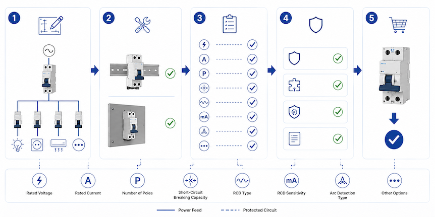
Once the architecture is decided, the AFDD schedule should be completed like any other engineered protective-device schedule. Each parameter represents a condition that the device must carry, detect, or interrupt.
Circuit Ratings: Voltage, Frequency, Current, and Poles
Confirm the nominal voltage, permitted voltage range, and supply frequency. The electronic detection circuit needs a valid supply; a 230 V, 50 Hz marking cannot be assumed suitable for 120 V, 60 Hz. If the product is marked for a range, confirm that all integrated protective functions operate throughout that range.
Identify single-phase, line-to-neutral, line-to-line, or other circuit arrangements. Check whether the device is 1P+N, two-pole, or another configuration, and which poles are protected and switched. Some products require designated line and neutral terminals or a specific supply/load orientation.
Rated current and conductor protection. The rated current is the continuous current the protective device can carry under defined conditions. It must satisfy the familiar coordination relationship between design current, protective-device rating, and conductor current-carrying capacity, with correction factors applied for ambient temperature, grouping, installation method, and thermal insulation.
Suppose a final circuit has a 13 A design current and its corrected conductor capacity is 18 A. A 16 A integrated AFDD-RCBO may be a candidate because the design current does not exceed the device rating and the device rating does not exceed the corrected conductor capacity. That simple check does not finish the design: voltage drop, disconnection time, inrush, terminal capacity, and board derating still matter.
Do not increase an AFDD from 16 A to 25 A merely to stop trips. If the trip indication shows overload, the load or circuit needs correction. If it shows an arc event, the higher current marking will not solve the arc signature and may leave the conductor underprotected.
Overcurrent Curve and Short-Circuit Capacity
For an integrated MCB or RCBO, the B, C, or other curve defines the instantaneous overcurrent operating range. C curve can tolerate more inrush than B curve, but it also needs higher fault current for instantaneous operation. The designer must verify the required automatic disconnection time using the applicable fault-loop or short-circuit calculation.
The curve does not adjust AFDD sensitivity. Changing curve to address an arc trip is a category error. Use trip indication and circuit testing to determine which function operated.
Breaking capacity and backup protection. The device’s rated short-circuit capacity must be adequate for the prospective short-circuit current at its installation point. A 6 kA device should not be selected for a calculated 8 kA location unless a manufacturer-documented backup arrangement increases the conditional capability under the exact conditions.
Where backup protection is used, record the upstream fuse or breaker model, rating, maximum prospective current, and applicable coordination table. A generic statement such as “protected by upstream MCCB” is not enough. The AFDD electronics do not compensate for contacts or terminals exposed beyond their short-circuit rating.
Residual-Current Sensitivity and Type
For an AFDD-RCBO, specify both rated residual operating current and RCD type. A 30 mA value is commonly associated with additional protection, but the applicable rule and circuit must be checked. It is a sensitivity value, not a universal fire-protection setting.
RCD type defines the residual-current waveforms the device can detect correctly. Type A is widely used where equipment can produce pulsating DC residual current. Loads involving frequency control, smooth DC components, or specialized power electronics may require another type according to the equipment instructions and national rules. Never assume that arc detection makes the residual-current type irrelevant.
Board, Busbar, Terminal, and Thermal Compatibility
Distribution-board compatibility deserves more than a photograph. Share the board series, rail, busbar geometry, phase position, terminal form, enclosure depth, module width, accessories, and maximum assembly current. A supplier can then recommend a suitable format and explain whether a new busbar, enclosure, or wiring arrangement is needed.
Check conductor material, cross-sectional range, stripping length, tightening torque, number of conductors allowed per terminal, and ferrule requirements. Confirm ambient-temperature and grouping derating. A row of heavily loaded electronic protective devices can run warmer than an isolated catalogue test condition.
For retrofit work, space must include conductor bending and safe access to test buttons and indicators. Replacing a one-module RCBO with a wider AFDD-RCBO can require a new enclosure. Moving circuits to make space can alter phase balance, RCD grouping, neutral routing, and schedules; it is not only a mechanical exercise.
Application Example: Choosing an AFDD for a Hotel Guest Room Circuit
The following hypothetical example shows how the decisions connect. It is not a universal design or a substitute for project calculations. Assume a 230 V, 50 Hz single-phase hotel-room socket circuit. The circuit supplies a maximum assessed load of 3.0 kW, uses copper conductors, requires 30 mA additional residual-current protection under the project rules, and originates in a compatible distribution board. The calculated prospective short-circuit current at the board is 3.4 kA. The applicable project risk assessment requires arc-fault protection because occupants sleep in the premises.
Step 1: Calculate the design current.
For this simplified single-phase resistive-equivalent assessment:
Ib = P / (V × PF)
where Ib is design current in amperes, P is active power in watts, V is circuit voltage in volts, and PF is power factor. Using 3,000 W, 230 V, and an assumed aggregate power factor of 0.95:
Ib = 3,000 / (230 × 0.95) = 13.7 A
A 16 A overcurrent function is a plausible starting point because its rated current exceeds the calculated 13.7 A design current. The result does not independently prove that 16 A is correct. The designer still needs the actual load profile, diversity rules, socket-circuit requirements, inrush behavior, and conductor calculation.
Step 2: Check the conductor relationship.
Assume the selected cable has a tabulated current-carrying capacity of 24 A under its reference installation method. The combined correction factor for ambient temperature, grouping, and thermal conditions is assumed to be 0.78. The corrected conductor capacity is:
Iz = It × C = 24 × 0.78 = 18.72 A
where Iz is corrected current-carrying capacity, It is tabulated capacity, and C is the combined correction factor. The basic relationship is then:
Ib ≤ In ≤ Iz
In this example, 13.7 A ≤ 16 A ≤ 18.72 A. That relationship supports a 16 A integrated overcurrent function under the stated assumptions. The engineer must still verify overload conventions under the applicable standard, voltage drop, conductor terminals, and required disconnection time. If later grouping reduces the correction factor, the same device and cable may no longer coordinate.
Step 3: Select the function combination.
The circuit needs arc-fault, residual-current, overload, and short-circuit protection. An AFDD integrated with an RCBO can provide those four functions at the circuit origin and avoid placing multiple room circuits behind one shared RCCB. A possible schedule entry begins with “AFDD-RCBO, 1P+N, 230 V AC, 50 Hz, 16 A, 30 mA.” It remains incomplete until curve, RCD type, short-circuit capacity, neutral switching, and board system are stated.
Assume the connected equipment includes laptop chargers, television power supplies, and other Class I and Class II electronic loads. The designer selects the RCD type from the expected residual-current waveforms and equipment instructions; Type A may be appropriate for common pulsating-DC-producing loads, but that choice must be confirmed rather than copied from this example. The overcurrent curve is selected from the inrush profile and fault-loop calculation, not from AFDD behavior.
Step 4: Check short-circuit and assembly conditions.
The measured or calculated prospective short-circuit current is 3.4 kA. A device with 6 kA rated short-circuit capacity could exceed that value, subject to the relevant product rating, test conditions, and board design. A 3 kA device would not be acceptable at this point. If an upstream protective device is used to achieve a higher conditional rating, the exact pair must appear in the manufacturer’s coordination data.
The proposed AFDD-RCBO must then be checked against the hotel distribution-board series. The review covers busbar part number and geometry, supply side, neutral connection, module width, enclosure depth, row current, adjacent-device derating, terminal size, and permitted accessories. If the device is two modules wide and the board schedule has only one spare way, selecting a compact unverified substitute is not an engineering solution. The board layout or approved product system must change.
Step 5: Confirm the complete product configuration.
The result is a 16 A AFDD-RCBO candidate for a 230 V, 50 Hz, 1P+N final circuit, with 30 mA residual-current protection and at least 6 kA short-circuit capacity under the example conditions. The remaining choices are the overcurrent curve, RCD type, neutral switching, module width, busbar connection, and trip-indication format.
This final check shows why no single calculation selects the whole product. The current calculation supports the 16 A rating but does not determine RCD type. The 6 kA value addresses prospective short-circuit current but does not confirm board compatibility. Each parameter answers a different technical question.
Review the Installation as a System, Not a Row of Devices
AFDD installation quality directly affects the hazard being controlled. Loose terminals, nicked conductors, mixed neutrals, and overheated enclosures can create faults or unwanted trips. Work should be performed by a qualified person using safe isolation, verification of absence of voltage, local wiring rules, and the manufacturer’s instructions.
Place protection at the final-circuit origin.
AFDDs are generally applied at the origin of the final circuit they protect. A downstream device leaves upstream cable outside its arc-fault coverage unless another approved measure protects that section. Do not assume that one AFDD at a distribution-board incomer provides equivalent protection for every final circuit.
Individual circuit protection also improves fault location and continuity. If one upstream device monitors many nonlinear loads, the combined signatures become more complex and a trip removes a wider area. Use only topologies permitted by the product instructions and installation standard.
Keep every line and neutral in the correct circuit.
Shared or crossed neutrals are a frequent cause of residual-current trips in boards with RCBO functions. They can also defeat isolation expectations. Trace the circuit before conversion, keep line and neutral associated, and follow the designated supply and load terminals.
Multiwire or shared-neutral arrangements require products and connection methods specifically accepted for that system. Do not split related conductors across independent single-pole devices without the required common operation and manufacturer approval.
Control termination and heat.
Prepare conductors without cutting strands, trapping insulation, or exposing excess copper. Use a calibrated torque tool at the value stated by the manufacturer. Do not put two conductors in a terminal unless it is designed and documented for that use. Recheck any connection disturbed during busbar installation.
Apply enclosure and device derating rules, especially in full boards, high ambient temperatures, or installations with sustained loads. If the manufacturer specifies spacing or maximum adjacent loading, include it in the layout review. A correct front-label rating can still be misapplied under a different thermal condition.
Protect continuity-critical loads deliberately.
Fire protection and continuity are both safety considerations. A trip on life-support equipment, safety services, refrigeration for medicines, alarms, or process controls can create another hazard. The answer is not to omit required protection casually. Use the local rules and a documented risk assessment to determine circuit separation, alarming, alternative supplies, redundancy, or another accepted protective measure.
Trip indication is especially valuable where restoration time matters. Specify whether the product distinguishes arc, residual-current, overcurrent, overtemperature, internal fault, and manual opening. Indicator behavior is manufacturer-specific; include its operating table in the handover documents.
How to Test an AFDD After Installation
Commissioning has two layers. Standard installation tests verify the wiring and conventional protective functions. The manufacturer’s functional procedure verifies designated AFDD electronics and opening behavior. Neither layer replaces the other.
- Inspect: Check model, ratings, certification markings, poles, line/load orientation, neutral, busbar engagement, conductor preparation, torque, labels, and enclosure compatibility.
- Verify the circuit: Complete continuity, insulation resistance, polarity, prospective fault-current or loop tests, and other tests required by the local installation standard.
- Test integrated protection: Where an RCD function is present, perform the specified RCD tests with suitable instruments and methods.
- Operate the AFDD test function: Follow the product instructions under the stated supply and handle conditions. Confirm opening, indication, and reset.
- Apply representative load: Check normal operation and record any unusual equipment restrictions stated by the manufacturer.
- Document: Record the exact part number, serial or batch where required, test results, trip-code guide, and replacement constraints.
Do not create a field arc by loosening a terminal, cutting insulation, or striking conductors. Such a test is unsafe and does not reproduce the standardized product test. Use only approved test equipment and procedures.
The test button is also easy to overstate. It checks functions defined by that product; it does not prove the condition of every downstream joint, confirm cable insulation, or demonstrate operation for every imaginable arc. Periodic inspection and testing remain necessary.
Use the Trip Cause Before Resetting
When an integrated AFDD trips, identify which function operated before resetting it. Some devices retain a mechanical indication; others show an LED sequence only during a defined reset or power-up procedure. Repeated switching can erase useful evidence.
| Observed condition | Likely investigation path | Unsafe shortcut to avoid |
|---|---|---|
| Arc indication after a particular load operates | Inspect its cord, plug, switch, internal connections, socket, and compatibility guidance | Replacing the AFDD with an MCB without testing the load |
| Residual-current indication | Check insulation, connected equipment, accumulated leakage, and crossed neutrals | Increasing RCD sensitivity value without design review |
| Overcurrent indication | Measure load, check inrush, short circuits, conductor protection, and selected curve | Installing a higher current rating to stop trips |
| Immediate trip after board modification | Verify line/load orientation, neutral association, busbar position, and wiring damage | Assuming a new device is defective before checking installation |
| Internal-fault or failed self-test indication | Follow manufacturer replacement and warranty instructions | Bypassing the electronic function permanently |
If no visible defect is found, disconnect portable loads and inspect accessible accessories under safe isolation. Reconnect equipment systematically only after required tests. For unusual electronic loads, provide the manufacturer with the AFDD model, production code, circuit data, load model, trip indication, and timing. “Nuisance trip” is a symptom description, not a diagnosis.
Frequently Asked AFDD Selection Questions
Does an AFDD replace an RCBO?
Only a product explicitly certified as an AFDD integrated with an RCBO provides arc, overload, short-circuit, and residual-current functions in one unit. A standalone AFDD does not automatically provide those functions. Read the markings, certificate scope, and data sheet.
How do I choose the AFDD current rating?
Coordinate the rating with design current, corrected conductor capacity, installation method, ambient temperature, grouping, and integrated overcurrent characteristics. Do not select it from the connected appliance rating alone or increase it to mask unexplained trips.
Is an AFDD mandatory on every final circuit?
No universal rule applies worldwide. The answer depends on the adopted installation standard, edition, building use, circuit purpose and rating, national amendments, and project requirements. Confirm the exact jurisdiction before producing the bill of materials.
What is the difference between AFDD and AFCI?
AFDD is normally associated with IEC 62606 and IEC-style installations. AFCI is the North American term associated with standards such as UL 1699 and local NEC requirements. They mitigate similar arc hazards but are not automatically interchangeable products.
Can one AFDD protect several final circuits?
Do not assume so. AFDDs are generally applied at the origin of the final circuit, and individual devices improve fault location and continuity. Any shared arrangement must be permitted by the applicable standard and the manufacturer’s instructions.
Why can an AFDD trip when an MCB and RCD would not?
The AFDD analyzes arc signatures rather than relying only on excessive current or earth-leakage imbalance. A series arc may remain at normal load current, while a line-to-neutral parallel arc may create no residual imbalance. The trip indication should still be checked because an integrated product may have operated for another function.
The Final AFDD Selection Rule
An AFDD choice is ready for quotation when four things are clear: the circuit application, the applicable market requirement, the protection functions and ratings, and the distribution-board interface. If the inquiry can state only “AFDD, 16 A,” the manufacturer will need more information before recommending the right model.
For B2B buyers, the easiest next step is to send the destination country, voltage and frequency, rated current, required protection combination, pole arrangement, short-circuit level, residual-current requirement, board details, quantity, and certification needs. You can contact JUTRION with these details to discuss suitable AFDD options, product documents, samples, and OEM/ODM requirements.
Technical References
- IEC 62606 consolidated edition 1.2 — General requirements for arc fault detection and protection devices
- IEC 60364-4-42:2024 — Protection against thermal effects
- IET — BS 7671 current edition and transition checker
- IET — BS 7671:2018+A4:2026 publications
- UL Solutions — AFCI device testing and certification
- BEAMA — Guide to arc fault detection devices
