

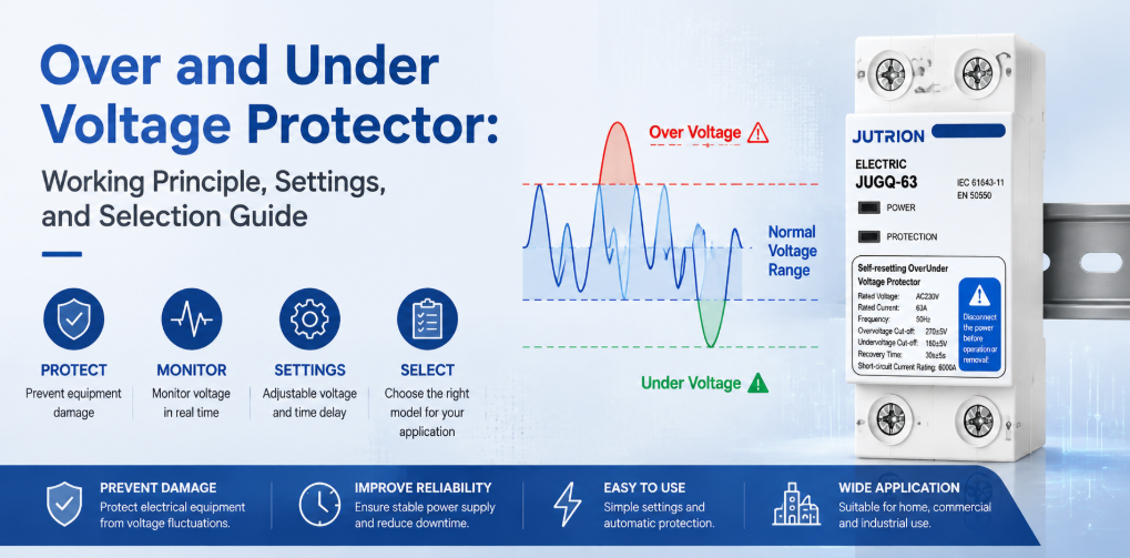
過電圧・不足電圧保護装置の動作原理と選定ガイドクイックアンサー:過電圧・不足電圧保護装置の役割とは?
過電圧・不足電圧保護装置は、供給電圧が選択された上限値または下限値を超えた状態が続く場合に回路を遮断し、電圧が回復してあらかじめ設定された遅延時間が経過した後に再接続します。持続的な過電圧、不足電圧、ブラウンアウトから保護します。ただし、SPD(一時的なサージ)、回路遮断器(過電流)、RCD(地絡)、AVR(連続的な電圧補正が必要な場合)の代わりにはなりません。.
“「電圧保護」はひとつのテーマとして扱われがちですが、配電盤は根本的に異なる複数の事象に直面する可能性があります。雷による一時的な過渡現象はマイクロ秒単位で終わることがあります。電力会社の電圧調整の問題や変圧器のタップ設定ミスは、供給電圧を通常範囲より数分間にわたって高い状態に保つことがあります。過負荷のフィーダーは長時間のブラウンアウトを引き起こすことがあります。三相4線式システムで中性線が緩んだり断線したりすると、一部の単相負荷に定格を大きく超える電圧がかかり、他の負荷には定格を下回る電圧がかかることがあります。.
これらのすべての状態に単一の装置で対応できるわけではありません。サージ保護装置は短時間の高エネルギーの過渡現象を制限します。過電圧・不足電圧保護装置は、RMS供給電圧が許容範囲外に留まる場合に負荷を遮断します。遮断器は過負荷および短絡電流を遮断します。RCDまたはRCBOは残留電流に反応します。したがって、最初の選定基準は電流定格や表示タイプではなく、装置を外乱に適合させることです。.
したがって、盤製作者や販売業者にとって有用な問いは、「電圧保護」が存在するかどうかではありません。有用な問いは、それぞれの外乱に対して、定義された検出方法、開閉応答、回復ルールが存在するかどうかです。.
保護境界:各電圧問題を適切な装置に対応させる
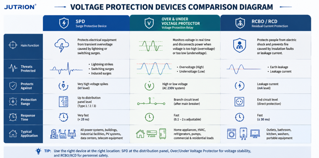
SPD、過電圧・不足電圧保護装置、RCBO RCDの機能を示す電圧保護装置比較図| 外乱 | 典型的な継続時間 | 主な対応 | 通常担当するデバイス |
|---|---|---|---|
| 雷または開閉サージ | マイクロ秒からミリ秒 | 過渡エネルギーをクランプして迂回させる | サージ保護デバイス(SPD) |
| 持続的過電圧 | 秒、分、またはそれ以上 | 影響を受ける負荷を切り離す | 過電圧保護装置または電圧監視リレー |
| 不足電圧またはブラウンアウト | 秒、分、またはそれ以上 | 機器が過熱、停止、または誤動作する前に切り離す | 不足電圧保護装置または電圧監視リレー |
| 過負荷または短絡 | 故障の大きさによる | 過大電流を遮断する | MCB または MCCB |
| 地絡漏電 | ミリ秒から持続的 | 残留電流を検出して切り離す | RCCB または RCBO |
| 連続的な補正を必要とする電圧変動 | 連続的または繰り返し | 電圧を昇圧、降圧、または調整する | 電圧安定装置またはAVR |
適切に設計されたパネルには、これらのデバイスが複数含まれることがあります。なぜなら、それらは異なる時間スケールで動作し、異なる電気量を監視するからです。SPDを設置しても、持続的過電圧保護が不要になるわけではありません。電圧保護装置を追加しても、小型遮断器の遮断容量が増加するわけではありません。正しい協調は加算的であり、競合的ではありません。.
電圧異常時に遮断器がトリップしない理由
従来の遮断器は主に電流に反応します。供給電圧が上昇しても、接続された機器が遮断器の時間-電流曲線を超えるほどの電流を直ちに引き込まない場合、敏感な電子機器が損傷する電気的ストレスを受けている間も、遮断器は閉じたままになる可能性があります。不足電圧時には、モーターが必要なトルクを生み出すためにより多くの電流を引き込む場合がありますが、正確な応答はモーター、負荷、およびコントローラによって異なります。遮断器は最終的にトリップするかもしれませんが、供給電圧が許容範囲内かどうかを監視するようには設計されていません。.
電圧保護装置は、電圧を直接測定することでこの盲点を補います。過電流保護も保護装置に統合されている場合、その機能は上流側の短絡保護デバイスと引き続き協調させる必要があります。上流側のMCBまたはMCCBは、安全な故障遮断のために不可欠です。.
過電圧・不足電圧保護装置の設置場所
過電圧・不足電圧保護装置は、電源と負荷または下流側の配電回路の間に使用される監視および開閉デバイスです。その検出回路は入力電圧をサンプリングします。コントローラは測定値を設定された上限および下限しきい値と比較します。電圧が該当する応答時間の間、許容ウィンドウの外にある場合、デバイスは開閉接点を開くか、外部コンタクタに開放を指令します。.
自動再投入モデルは、負荷が切り離されている間も電源を監視し続けます。電圧が回復限界内に戻ると、コントローラは再接続遅延を開始します。負荷は、その遅延中ずっと供給が許容範囲内に留まった場合にのみ復旧します。これにより、急速なオンオフサイクルを防ぎ、コンプレッサー、冷凍システム、電子電源、およびその他の機器に再起動前に安定する時間を与えます。.
一般的な名称には、過電圧・不足電圧保護装置、電圧保護デバイス、自動電圧切替器、自己復帰型電圧保護装置、自動再投入保護装置、電圧監視リレーなどがあります。これらの用語は重複していますが、常に同一の製品を指すとは限りません。負荷を直接開閉するユニットもあれば、外部用のリレー接点を提供するユニットもあります ACコンタクタ. 。電圧のみを監視するものもあれば、電流測定、過電流保護、欠相監視、またはデジタル表示を追加するものもあります。.
持続的過電圧と不足電圧が機器に与える影響
持続的過電圧
持続的過電圧は絶縁ストレスを増大させ、絶縁劣化を加速させる可能性があります。電源コンデンサ、MOV、LEDドライバ、制御トランス、半導体入力は、設計限界に近い、またはそれを超えた状態で動作する可能性があります。抵抗が一定の場合、抵抗性加熱電力は電圧の2乗にほぼ比例して増加するため、中程度の電圧上昇でも発熱はより大きく増加する可能性があります。その結果、即時故障、不要なシャットダウン、または元の供給事象と結びつけにくい耐用年数の短縮が生じる可能性があります。.
考えられる原因には、不適切なトランスタップ、レギュレータ故障、配線ミス、発電機のAVR問題、負荷遮断、中性線故障、接続機器に適さない電源が含まれます。電圧保護装置は原因を修復することはできませんが、その状態が続く間、負荷を切り離すことができます。.
不足電圧とブラウンアウト
不足電圧は単に「電力が少ない」ということではありません。モーターは加速に失敗したり、負荷がかかると停止したりする可能性があります。接触器はチャタリングしたり、開放したりする可能性があります。リレーやコントローラは予測不能にリセットされる可能性があります。定電力電子負荷は電圧が低下するとより多くの電流を引き込もうとする場合があり、導体や部品への熱ストレスが増大します。冷凍コンプレッサは、圧力が均等化する前に再起動が繰り返されることに特に敏感です。.
正しい対応は負荷によって異なります。一部の電子機器は広い入力範囲を持ち、中程度の電圧低下を乗り切ることができます。モーター駆動ポンプは高速な切り離しが必要な場合があります。重要な制御システムは、単純な切り離しではなくUPSを必要とする場合があります。したがって、保護装置のしきい値と遅延は、他のパネルから盲目的にコピーするのではなく、機器の要件から選択する必要があります。.
中性線断線:重要な三相4線式の危険
平衡三相4線式システムでは、相-中性線負荷が類似しており、中性線電流は比較的低くなる可能性があります。実際の設備が完全に平衡していることはまれです。不均等な単相負荷の上流で中性線導体が緩んだり断線したりすると、中性点が移動する可能性があります。相-中性線電圧は、定格値に固定されたままではなく、負荷インピーダンスによって決定されます。.
相間電圧が正常に見えても、一方の負荷群が深刻な過電圧を受け、他方が不足電圧を受ける可能性があります。このため、中性線断線事象は、商業、住宅、通信、軽工業の混在パネルにおいて特に危険です。通常の過電流装置がトリップするほど大きな故障を検出する前に、機器の損傷が発生する可能性があります。.
三相電圧監視構成では、関連するすべての相と、用途で必要な場合は相-中性線電圧を評価する必要があります。欠相、相不平衡、中性線の健全性を明示的に考慮する必要があります。1つの相での単一測定は、三相4線式負荷の完全な監視の代わりにはなりません。.
設計上の注意: 電圧保護装置は機器の曝露を低減しますが、欠陥のある中性線を安全にするものではありません。緩んだ端子、サイズ不足の導体、腐食、上流のネットワーク故障を発見し、修正する必要があります。.
単相保護と三相保護は異なる判断です
単相プロテクタは通常、1つの中心的な判断を行います。測定された線間-中性線間電圧が承認された動作範囲内にあるかどうかです。これは単純に聞こえますが、設置時には依然として、公称電圧、機器が流す電流、1本または2本の導体を開閉する必要があるかどうか、そして地域の接地方式において中性線がどのように扱われるかを定義する必要があります。公称230 V回路用と表示された製品を、63 Aの電流表示だけで選定することはできません。.
単相用途には一般に、アパート、小規模店舗、通信キャビネット、冷凍回路、照明盤、個別機械が含まれます。これらの負荷は同じ事象に対して非常に異なる反応を示す場合があります。LEDドライバは、コンタクタコイルを開放させる短時間の電圧低下には耐えられるかもしれません。冷蔵庫は電圧低下には耐えても、直後の再始動によって損傷する可能性があります。したがって、適切に選定されたプロテクタは、正しい電圧範囲と、下流で最も再始動に敏感な負荷に適した復帰遅延を組み合わせます。.
三相プロテクタが監視する必要がある可能性のある項目
三相保護は、単相測定の3つのコピーではありません。監視機能は、線間電圧、相-中性線間電圧、欠相、相順、電圧不平衡を評価する必要がある場合があります。どの機能が重要かは、負荷と導体の配置によって異なります。三相モータフィーダは、多数の不均等な単相回路に給電する四線式分電盤とは異なるリスクプロファイルを持ちます。.
- 欠相 供給相の1つが欠落または崩壊していることを意味します。運転中の三相モーターは、残りの相に過大な電流が流れ、トルクが低下し、急速に加熱されながら運転を続ける可能性があります。モーター関連用途向けの保護装置は、この状態を検出するか、それを検出するモーター保護リレーと連携する必要があります。.
- 相順 多くの三相モーターの回転方向を決定します。通常、試運転時や供給配線の変更後に重要になります。過電圧・不足電圧機能は相順保護を自動的に意味するわけではないため、必要な機能を明示する必要があります。.
- 電圧不平衡 相電圧が等しくない状態を表します。一見わずかな電圧不平衡でも、モーターにははるかに大きな電流不平衡が生じる可能性があります。許容限度はモーターとシステムの設計から決めるべきです。広い過電圧・不足電圧しきい値でのみトリップする装置では、専用の不平衡監視が提供されない場合があります。.
- 中性点変位 相-中性線間の負荷が不均等な場合に重要です。三相装置が相間値のみを測定する場合、中性線の断線によって生じる有害な相-中性線間の分離を検出できない可能性があります。盤製作者は、リストの「三相」という表記に頼るのではなく、選択した装置が実際にどの電圧を検出するのかを正確に確認する必要があります。.
| 系統と負荷 | 優先すべき測定項目 | 一般的な開閉方式 |
|---|---|---|
| 230 V単相最終分電 | 相-中性線間の過電圧および不足電圧 | 定格と協調が許す場合は直接開閉 |
| 400 V三相モーターフィーダー | 相間電圧、欠相、不平衡、および場合により相順 | モーター定格コンタクターを制御する監視装置 |
| 400/230 V 4線式混合負荷盤 | 関連するすべての相-中性線間電圧、欠相、および中性線関連の変位 | 接地方式に応じて選定される多極遮断 |
| 発電機バックアップ配電 | 有効電源の電圧、および必要に応じて周波数と切替系統の状態 | 発電機コントローラーおよび切替装置と連携 |
この区別は製品比較にも影響します。コンパクトな単相自己復帰型保護装置は、コンシューマーユニットには優れた装置かもしれませんが、大型三相モーター盤には誤った制御アーキテクチャとなります。逆に、複雑な相監視リレーとコンタクターの組み合わせは、標準化された単相回路には不要なコストと盤スペースを追加する可能性があります。正しい選択は、実際の負荷に害を及ぼす可能性のあるすべての電圧状態を監視する最小のアーキテクチャです。.
自動再投入型電圧保護装置の動作原理
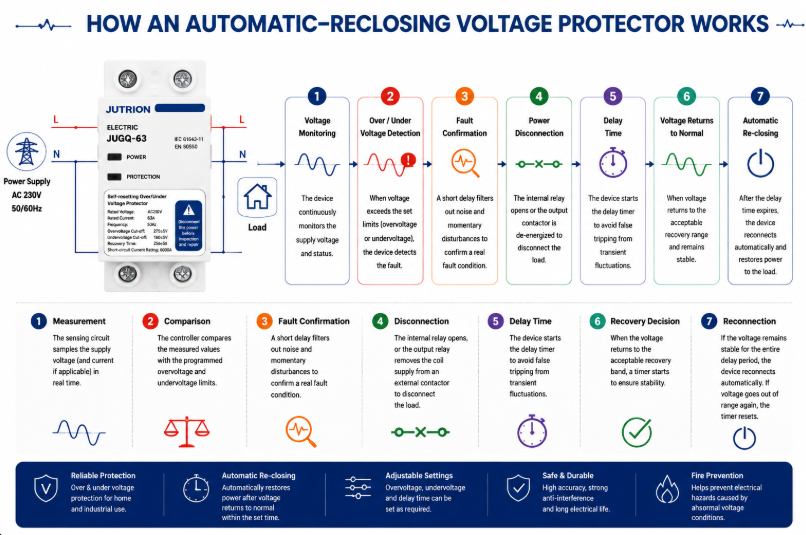
自動再投入型電圧保護装置 動作原理図- 測定: 検出回路が供給電圧をサンプリングし、該当するモデルでは電流または追加の相状態もサンプリングします。.
- 比較: コントローラーが測定値をプログラムされた過電圧・不足電圧限度と比較します。.
- 故障確認: フィルタリングまたはトリップ遅延により、負荷を切り離すべきでない重要でないノイズやごく短時間の外乱を排除します。.
- 遮断: 内部接点が開くか、出力リレーが外部コンタクターのコイル供給を遮断します。.
- 監視継続: 下流側の負荷が切り離されている間も電源の監視が続きます。.
- 復帰判定: 電圧が許容復帰帯域に戻ると、タイマーが開始します。.
- 再接続: 電源が全遅延時間にわたって安定している場合、装置は自動的に再接続します。電圧が再び許容範囲外になった場合、タイマーはリセットされます。.
マイクロプロセッサ方式のデジタルサンプリングにより、調整可能なしきい値、時間遅延、表示、状態ロジックをコンパクトなDINレール機器で実用化できます。電気的ノイズの多い設置環境ではフィルタリングが重要です。不要トリップは電圧事象そのものとほぼ同じくらい運用を妨げる可能性があるためです。フィルタと確認時間は、負荷に損傷を与えかねない持続的な状態を見逃すことなく、重要でない偏差を除外する必要があります。.
トリップレベル、復帰レベル、遅延が連携して機能する必要がある理由
保護装置は電圧に関する判断を1つだけ行うのではありません。通常、少なくとも3つの関連する判断を行います。すなわち、供給が許容不能になった時点、再び許容可能と見なせるまで回復した時点、そして負荷を再接続する前に安定を維持しなければならない時間です。これらの値は1つの制御戦略を構成するため、まとめて検討する必要があります。.
トリップレベルと復帰レベルが近すぎると、境界付近で変動する供給により開閉が繰り返される可能性があります。別個の復帰値を設けることでヒステリシスが生まれます。例えば不足電圧トリップ後、再接続が可能になるには電圧がより健全なレベルまで上昇する必要があります。再接続タイマーは、その回復が一時的ではなく安定的であることを確認します。.
正しいタイミングは負荷に応じて決まります。抵抗ヒーターは比較的迅速な復帰を受け入れられる場合があります。冷凍コンプレッサーは再始動前により長い休止時間を必要とする場合があります。複数のモーターを備えた盤では、合計突入電流によって供給が再びしきい値を下回らないよう、段階的な再接続が必要になる場合があります。このため、調整可能な遅延は単なる便利機能ではなく、工学的なパラメータなのです。.
調整可能なモデルの場合、承認されたトリップ値、復帰値、遅延値を1つの設定セットとして記録してください。高しきい値または低しきい値のみを変更すると、意図したヒステリシスと再始動動作が変わってしまう可能性があります。工場校正済みモデルの場合、プロジェクト全体で標準化する前に、プリセットの制御ウィンドウが供給先の電源と接続機器に適合していることを確認してください。.
過電圧・不足電圧保護装置の選定方法
系統電圧、周波数、相構成の確認
カタログの見出しではなく、実際の配電システムから始めてください。公称の相-中性線間電圧と相間電圧、周波数、単相または三相構成、導体数、中性線の使用、許容供給公差を記録します。IEC 60038は一般的な230/400 V低圧系統を含む標準電圧基準を提供しますが、最終的な要件はプロジェクト仕様と地域の供給規則によって決まります。.
三相負荷の場合、装置が欠相、相順、不平衡、相-中性線間の偏位も監視する必要があるかどうかを判断します。多数の単相負荷を含む盤では、平衡三相3線式モーター負荷よりも中性線関連の監視が重要になる場合があります。.
2. Define the Load That Will Be Disconnected
List the connected load, maximum demand, continuous current, inrush current and load type. A 40 A resistive circuit, a 40 A motor feeder and a 40 A bank of switched-mode power supplies do not impose identical switching duty. Identify compressors, pumps, transformers, capacitive inputs and equipment with internal undervoltage or restart controls.
Do not select solely from the service breaker rating. The protector must be suitable for the current it carries and the switching duty it performs, while the upstream protective device must provide the required short-circuit protection. Terminal capacity, conductor size, ambient temperature and enclosure ventilation also matter.
3. Decide Between Direct Switching and an External Contactor
A compact protector can switch a suitably rated load directly when its contact rating, utilization duty and prospective fault coordination are appropriate. For a larger panel, a motor-heavy load, frequent operation or a current beyond the protector’s direct-switching capability, use a monitoring relay or protector to control a correctly selected contactor. This separates the measurement logic from the power switching duty.
When an external contactor is used, check coil voltage, contactor utilization category, auxiliary contacts, control-circuit protection and fail-safe behavior. Decide what happens after a power loss and whether automatic restart is permitted by the process risk assessment.
4. Set the Overvoltage and Undervoltage Limits
The trip window should be wide enough to tolerate normal supply variation and narrow enough to protect the connected equipment. Use the most restrictive credible requirement from the equipment manufacturer, project specification and local installation rules. A value seen in a generic example is not automatically suitable for motors, refrigeration, medical equipment, telecom power supplies or process controls.
| Setting | Purpose | Selection question |
|---|---|---|
| Overvoltage trip level | Defines the high-voltage disconnection point | What sustained input can the most sensitive connected equipment tolerate? |
| Undervoltage trip level | Defines the low-voltage disconnection point | At what voltage can motors, contactors or power supplies no longer operate safely? |
| Trip delay | Rejects brief deviations | Which short disturbances can the load ride through without harm? |
| Recovery level | Defines when voltage is acceptable again | Is sufficient hysteresis provided to avoid repeated switching? |
| 再接続遅延 | Waits for stable supply and safe restart | Does the load need seconds or minutes before restart? |
5. Select Reconnection Delay for the Load
A short delay can restore lighting or non-critical resistive loads quickly. Refrigeration and air-conditioning compressors often require a longer delay to allow pressure equalization and avoid a hard restart. Multiple loads reconnecting simultaneously can create a new voltage dip, so large installations may require staged restarting rather than one common timer.
Automatic reconnection is convenient, but it is not appropriate everywhere. Machinery that could move unexpectedly may require manual reset, a safety controller or another supervised restart sequence. Voltage restoration must never bypass machine-safety requirements.
6. Check Poles, Neutral Arrangement and Isolation
Select the number of poles from the system earthing arrangement and installation requirements. Switching the neutral is not a universal rule. In some systems it is required; in others it may be prohibited or unnecessary. The choice must be coordinated with upstream bonding, source transfer arrangements and local codes. Never treat a two-pole or four-pole catalogue option as proof that it is correct for every network.
7. Verify Coordination and Installation Conditions
Confirm rated current, operational voltage, frequency, terminal capacity, mounting method, temperature range, enclosure protection and the required upstream protective device. Check short-circuit coordination rather than assuming a small modular device can interrupt any available fault current. Verify conductor torque and provide working space and ventilation according to the manufacturer’s instructions.
IEC 60364-4-44 addresses protection of low-voltage installations against voltage disturbances and electromagnetic disturbances. Apply the edition and national adoption required by the destination market; do not use an IEC reference as a substitute for a complete project design.
Standards and Export-Market Questions That Change the Specification
Standards references should define the engineering boundary, not decorate a product description. IEC 60364-4-44:2024 addresses protection of low-voltage installations against voltage disturbances and electromagnetic disturbances. It is an installation-level document: it helps designers consider the consequences of disturbances within an electrical installation, but it is not a model datasheet and does not by itself prove that a particular protector is suitable for a project.
IEC 60038 defines standard voltage values used as references for equipment and supply systems. Nominal voltage is the starting point for a protector setting, not the complete setting decision. Normal service variation, the connected equipment’s permissible input range, regional supply-quality requirements and the behavior of the recovery logic all affect the usable window.
Product Standard, Installation Code and Supply Quality
These three layers answer different questions. A product standard describes how a device is classified, constructed and tested. An installation code determines how equipment is selected and erected in a building or plant. A supply-quality document describes characteristics expected at the point of supply. A buyer should not substitute one layer for another. For example, knowing that a country uses a 230/400 V nominal system does not determine the required neutral switching, and an installation-code reference does not establish the short-circuit capability of an individual product.
The destination market may also use a national adoption of an IEC document with local modifications. North American projects use different system conventions, product listings and installation rules. The familiar functions—measure, compare, disconnect and delay reconnection—remain understandable, but product acceptance, conductor switching, enclosure marking and coordination have to be checked in the regional framework.
Certification Claims Must Match the Exact Model
Terms such as IEC, UL and CB should be supported by documentation that identifies the relevant standard, model or series, electrical ratings and issuing body. A general factory capability statement is not the same as a certificate covering every variant. Importers and panel builders should match the document reference to the ordered catalogue number and destination-market requirement.
The same discipline applies to rated current and protection claims. If a series includes several current or pole variants, evidence for one variant should not automatically be extended to all others. Where a protector includes overcurrent functionality, clarify its operating characteristic and its relationship to the upstream breaker. “Overcurrent” on a display does not automatically mean the device provides the short-circuit interruption performance expected from an MCB or MCCB.
A Compact Export Specification
Before comparing models, put the project conditions on one line: destination market; nominal voltage and frequency; phase and neutral arrangement; continuous current and load type; overvoltage and undervoltage limits; trip and reconnection timing; number of switched poles; direct switching or contactor control; upstream protection; mounting and environmental conditions; and required conformity documents. That line exposes mismatches quickly and prevents three products with the same front-panel current marking from being treated as equivalent.
For distributors serving several countries, adjustable models can reduce stock fragmentation, but only when setting control is managed. A setting range is useful if commissioning personnel know the approved values and unauthorized changes are prevented. For one stable market and a repeatable panel design, factory-calibrated thresholds may produce more consistent installation and simpler training. The export decision is therefore partly electrical and partly operational.
Choosing Between the Three JUTRION Series
JUTRION offers three 過電圧・不足電圧保護装置 series for different panel and procurement priorities. Product selection should still be confirmed against the required electrical ratings and project documentation.
| Selection point | JRGQ-63 | JQGQ-63 | JUGQ-63 |
|---|---|---|---|
| Series position | Flagship adjustable model | Compact digital model | Cost-effective preset model |
| Display and monitoring | Dual digital display with real-time voltage and current monitoring | Compact digital display with smart monitoring | Simplified interface for plug-and-play use |
| Voltage settings | Adjustable overvoltage and undervoltage parameters | Adjustable thresholds | Factory-calibrated thresholds |
| Additional function stated on the public page | Overcurrent protection and automatic reclosing | Automatic reclosing | Automatic reclosing |
| Installation format | 35 mm DIN-rail modular format | Space-saving DIN-rail format | Streamlined DIN-rail format |
| Best fit | Projects needing visible operating data and broad parameter control | High-density distribution boards where space matters | Standardized, high-volume applications requiring simple installation |
| Confirm from the ordered model datasheet | Rated voltage, current, poles, exact setting and delay ranges, terminals, temperature limits, dimensions, switching duty, upstream protection and model-specific conformity documents | ||
Choose JRGQ-63 when adjustment, current information and a more complete on-device interface are valuable. Choose JQGQ-63 when adjustable digital protection is needed but panel density is the main constraint. Choose JUGQ-63 when the required protection window matches the factory-calibrated configuration and consistency, simplicity and volume economics are more important than field adjustment.
A buyer should not compare only unit price. Normalize rated voltage, current, poles, adjustable range, trip and recovery logic, delay range, switching method, display, overcurrent function, terminals, certifications, packaging and customization. Two devices described as “63 A automatic voltage protectors” can offer materially different functions.
Apply the Selection Logic to Four Panel Scenarios
Commercial Distribution Board on an Unstable Grid
A small commercial facility experiences long evening brownouts and occasional high voltage during light-load periods. The panel supplies lighting, point-of-sale equipment, refrigeration and office electronics. A voltage protector can disconnect selected downstream circuits outside the approved window. Because refrigeration has a different restart requirement from lighting and office loads, the designer may divide the loads or use separate control so one common reconnection delay does not compromise either continuity or compressor protection.
OEM Panel for Pumps or HVAC Equipment
The load includes motors with high starting current and a control circuit sensitive to low voltage. Direct switching through a compact protector may not be the preferred architecture. The protector can monitor the source and command an AC contactor selected for the motor duty. The control design should prevent unsafe automatic restart and coordinate undervoltage behavior with the motor protection relay and process controller.
Three-Phase Panel with Many Single-Phase Loads
A 400/230 V panel distributes different single-phase circuits across the three phases. Unequal loading makes an open neutral hazardous. The monitoring strategy should observe all relevant phase-to-neutral voltages and disconnect the affected distribution section if values diverge beyond permitted limits. Maintenance procedures must still locate and repair the neutral fault.
High-Volume Standardized Consumer Unit
An OEM produces many panels for one market with a stable, predefined protection specification. Field adjustment is not needed and could create commissioning inconsistency. A factory-calibrated automatic-reclosing model such as JUGQ-63 may provide a simpler fit, provided its nominal voltage, current, thresholds, poles and certification match the project.
Install, Commission, and Diagnose the Protection System
Installation and Commissioning Checklist
- Confirm the source is isolated and follow the project’s lockout procedure.
- Verify nominal voltage, frequency, phase arrangement and conductor identification.
- Confirm whether the protector switches the load directly or controls a contactor.
- Check upstream short-circuit and overload protection.
- Match conductor size and terminal capacity; tighten to the specified torque.
- Program thresholds and delays from the approved setting schedule.
- Test overvoltage and undervoltage operation with suitable test equipment rather than by creating unsafe supply conditions.
- Verify the trip indication, contact state and reconnection timer.
- Confirm that motors and machinery restart safely.
- Record settings, model, serial or batch information and commissioning results.
After commissioning, investigate frequent trips instead of simply widening thresholds. Repeated operation may reveal a loose neutral, undersized feeder, overloaded transformer, generator-control issue or supply-quality problem. The protector is often the messenger, not the cause.
Common Selection and Installation Mistakes
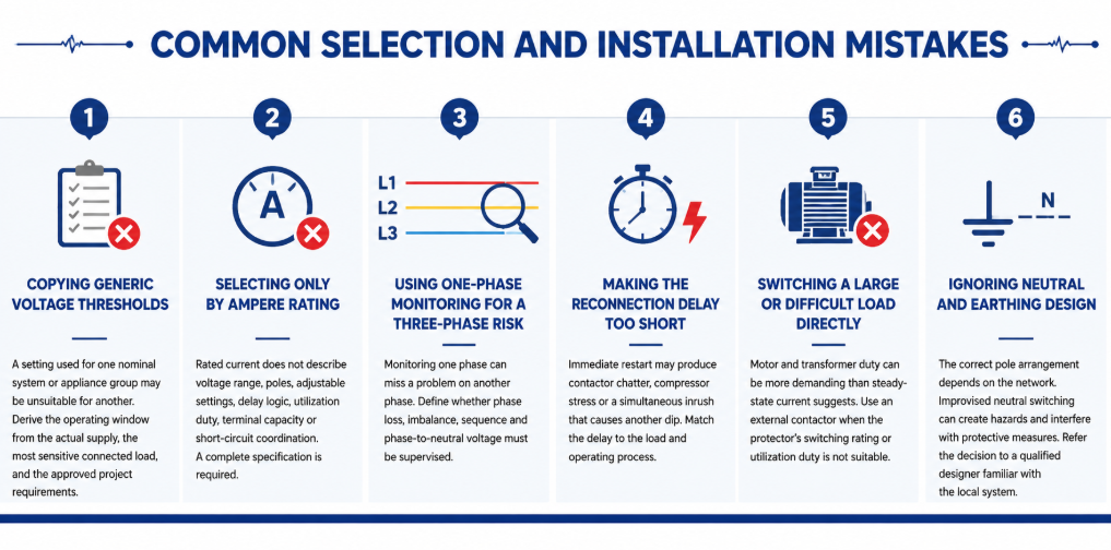
Common selection and installation mistakes of automatic re-closing voltage protector- Copying generic voltage thresholds: A setting used for one nominal system or appliance group may be unsuitable for another. Derive the operating window from the actual supply, the most sensitive connected load, and the approved project requirements.
- Selecting only by ampere rating: Rated current does not describe voltage range, poles, adjustable settings, delay logic, utilization duty, terminal capacity or short-circuit coordination. A complete specification is required.
- Using one-phase monitoring for a three-phase risk: Monitoring one phase can miss a problem on another phase. Define whether phase loss, imbalance, sequence and phase-to-neutral voltage must be supervised.
- Making the reconnection delay too short: Immediate restart may produce contactor chatter, compressor stress or a simultaneous inrush that causes another dip. Match the delay to the load and operating process.
- Switching a large or difficult load directly: Motor and transformer duty can be more demanding than steady-state current suggests. Use an external contactor when the protector’s switching rating or utilization duty is not suitable.
- Ignoring neutral and earthing design: The correct pole arrangement depends on the network. Improvised neutral switching can create hazards and interfere with protective measures. Refer the decision to a qualified designer familiar with the local system.
Maintenance and Troubleshooting in Service
A voltage protector normally requires little routine intervention, but it should still be included in the panel inspection plan. Check for discoloration, heat damage, loose terminals, dust accumulation, cracked housings and abnormal display values. Compare the displayed voltage with a calibrated instrument when readings appear doubtful. Thermal imaging under representative load can help reveal a poor terminal connection, although it does not replace torque checks performed under safe isolated conditions.
Keep a record of trip events where operational continuity matters. The time, displayed voltage, affected phase, connected load and recovery time can distinguish a supply-quality issue from a load-related voltage drop. Several trips at the same production time may indicate feeder demand. Random high and low readings across single-phase circuits may point toward a neutral problem. Trips only during generator operation may indicate AVR settings, frequency variation or poor generator/load matching.
| Observed symptom | Possible causes to investigate | Useful checks |
|---|---|---|
| Trips immediately after installation | Wrong nominal-voltage model, wiring error, threshold set too close to normal supply | Verify model, line/neutral connections, measured voltage and setting schedule |
| Repeated trip and reconnect cycle | Insufficient hysteresis, unstable supply, restart inrush causing another dip | Record voltage during restart; review recovery level and delay |
| Display is on but load remains off | Active fault, delay still counting, damaged contact, external contactor/control issue | Read status indication and test control circuit according to the manual |
| One phase shows abnormal voltage | Loose phase or neutral, phase imbalance, upstream connection fault | Isolate safely and inspect all conductors; measure every relevant phase |
| Terminal temperature is high | Loose termination, unsuitable conductor, overload, poor enclosure ventilation | Measure load current, inspect conductor preparation and verify specified torque |
Do not repeatedly reset or bypass a protector until the cause is known. Bypassing removes the protection at the moment the system may be demonstrating a genuine fault. If the device has switched a severe or repeated load, inspect its contacts and connected conductors according to the manufacturer’s service instructions. Replace a unit that shows heat damage, unreliable switching or readings outside its declared accuracy rather than attempting an unapproved repair.
Settings should also be controlled. For adjustable models, record the approved values during commissioning and restrict unauthorized changes. If equipment is added, the supply changes, or the panel is exported to a market with a different nominal voltage, review the entire setting schedule. A protector that was correctly configured for the original installation may be inappropriate after a system modification.
よくある質問
なぜプロテクターは負荷を再接続する前に待機するのですか?
遅延は、電圧が回復したことを確認し、急速なサイクリングを防ぎます。また、コンプレッサーに再起動時間を提供し、同時突入電流によって電源が再び低下する可能性を減らすことができます。.
中性線の欠落から保護できますか?
影響を受ける相と中性線間の電圧を監視し、それらが許容範囲を外れたときに切断すれば、曝露を低減できます。中性線の故障を修復することはできず、監視構成は関連するすべての相をカバーする必要があります。.
過電圧/不足電圧保護装置は電圧安定装置と同じですか?
いいえ。プロテクターは負荷を切り離します。スタビライザーまたはAVRは、供給を継続しながら出力電圧を補正しようとします。停止が必要か、連続した安定化電力が必要かに応じて選択してください。.
アンペア定格はどうやって選べばよいですか?
装置が流す最大電流を決定し、負荷の使用率と突入電流を考慮し、必要な端子と設置条件に合った適切な定格を選び、上流側の故障保護と協調させてください。直接開閉が適さない場合は、外部コンタクタを使用してください。.
再接続の遅延はどれくらいにすべきですか?
Use the connected equipment manufacturer’s requirement and the process risk assessment. General lighting may accept a short delay; compressors and staged systems may need substantially longer or sequenced reconnection.
なぜ保護装置は何度もトリップするのですか?
考えられる原因には、実際の供給変動、中性線の緩み、過負荷のフィーダ、発電機の調整問題、誤った設定、配線ミス、または機器/負荷の不整合が含まれます。しきい値を広げる前に、システムを測定して診断してください。.
Choose the Protection Boundary Before the Product Variant
An over and under voltage protector is most effective when its operating window is defined precisely. Selection becomes a practical sequence: establish the nominal system and monitored conductors, understand the load, choose direct switching or contactor control, set coordinated trip and recovery values, choose a safe reconnection delay, verify poles and neutral design, and test the completed panel under controlled conditions.
For a model recommendation, send JUTRION the nominal voltage and frequency, phase and neutral arrangement, load current and type, required thresholds and delay, pole configuration, upstream protective device, installation conditions, certification market and order quantity. The JRGQ-63, JQGQ-63 and JUGQ-63 ranges can then be compared against the actual project instead of selected from current rating alone.
