

B Curve vs C Curve vs D Curve MCB: How to Choose the Right Trip Curve
A B20 and a C20 miniature circuit breaker can carry the same nominal current yet behave differently when a machine starts. That difference matters when a panel runs normally all day but trips each time a transformer, pump or group of electronic power supplies is energized.
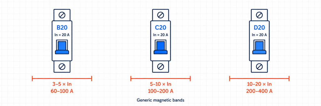
Choose the lowest magnetic trip characteristic that tolerates the load’s normal starting current while still meeting the circuit’s fault-disconnection requirements. In the common IEC 60898-1 framework, B curve has a magnetic operating band of 3–5 times rated current, C curve 5–10 times, and D curve 10–20 times. B is a useful starting point for low-inrush loads, C for moderate inrush, and D for genuinely high-inrush duties—not a universal cure for unwanted tripping.
The practical decision is not which curve is “stronger.” It is whether the breaker can distinguish, through its current-and-time response, between a normal start and a fault that must be disconnected.
Which MCB Curve Should You Investigate First?
| Circuit or symptom | First choice to investigate | What determines the finished choice? |
|---|---|---|
| Low-inrush resistive heating | B | Load current, corrected cable capacity and fault disconnection |
| Small motor with moderate starting demand | C | Starting current and acceleration time; separate motor overload protection |
| LED drivers or electronic power supplies switched together | Manufacturer’s loading table; compare B and C | Number of inputs, pulse duration and simultaneous energization |
| Transformer or genuinely high-inrush machine | D or an equipment-specific protection arrangement | Equipment recommendations and sufficient fault-disconnection performance |
| Long cable or current-limited backup source | The lowest curve compatible with startup | Minimum relevant fault current under the weakest supply condition |
| Trip after sustained operation, rather than at startup | Investigate load and heat before changing the curve | Actual current, cabinet temperature, grouping and connection condition |
Start with the row that describes the circuit, then check both startup and fault behavior. For general sockets, identify the permitted equipment and destination-market practice rather than treating either B or C as a universal default.
B20, C20 and D20: The Same Rating, Different Magnetic Response
The number identifies the rated current, In, in amperes. The letter identifies the overcurrent characteristic. A C20 is therefore a 20 A device with a C characteristic; it is not a 100 A device simply because its magnetic band starts around five times 20 A.
| Curve | Magnetic band | For In = 20 A | Useful starting point | Main selection concern |
|---|---|---|---|---|
| B | 3–5 × In | 60–100 A | Low-inrush resistive and final-circuit loads | Normal energization may reach the magnetic operating region |
| C | 5–10 × In | 100–200 A | Moderate-inrush loads and mixed equipment circuits | The minimum fault current must still support the required disconnection |
| D | 10–20 × In | 200–400 A | High-inrush equipment where the circuit supports the fault duty | Weak sources or long runs may not provide enough current for assured magnetic operation |
These ranges describe a band, not one exact trip point. A B20 should not be assumed to operate magnetically at precisely 60 A or precisely 100 A in every condition. Hager’s modular circuit-protection FAQ gives the familiar B, C and D ranges for its MCBs.
Also check the actual product family. For example, Schneider Electric’s Acti9 curve explanation lists a narrower 10–14 × In D range. That manufacturer-specific value should not be silently substituted for the generic 10–20 × In reference, or applied to a different brand.
If the device family has not yet been decided, start with the MCB, MCCB, RCCB and RCBO comparison. Curve selection is the next step after identifying the required protection functions.
Starting Current Must Be Read Together with Time
A high current peak does not, by itself, tell you whether the breaker will trip. The waveform and the time for which the current persists matter. A brief capacitor-charging pulse and a motor accelerating for several seconds can have similar headline current values but create different demands on the protective device.
A conventional thermal-magnetic MCB combines a delayed thermal response to sustained overload with a rapid electromagnetic response to high current. ABB’s white paper on MCB protection characteristics explains these mechanisms and the tolerance bands used in published curves.
Changing B to C or D mainly changes the magnetic characteristic. It does not authorize a higher continuous load, remove thermal overload protection, or make a cable suitable for more current.
To assess a start, gather more than the normal running current:
- Magnitude: use the equipment manufacturer’s starting-current data or a suitable measured waveform.
- Duration: distinguish a very brief input pulse from an acceleration period or prolonged abnormal start.
- Switching pattern: identify which loads energize together and which start separately.
- Repetition: consider frequent starts, hot restarts and the breaker’s existing load and thermal state.
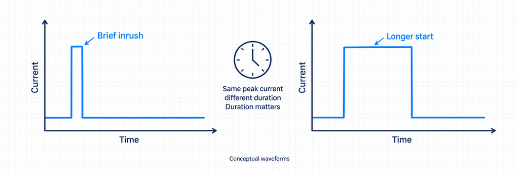
Check how the source defines its current value. A peak measured in amperes is not automatically interchangeable with an RMS current multiple on a manufacturer’s curve. Very short electronic-load pulses may need the supplier’s maximum-device-per-breaker table or specific inrush compatibility data rather than a simple comparison against 3, 5 or 10 × In.
This is particularly important for LED drivers and switched-mode power supplies. Low operating wattage does not guarantee low aggregate inrush. Several inputs charging at the same switching event can make a lightly loaded circuit difficult to energize.
The Fault Side of the Decision Is Easy to Miss
A curve that successfully rides through startup must still disconnect real faults quickly enough. Raising the magnetic threshold creates a second question: will the circuit provide enough fault current at its least favorable point?
Consider the difference between these two values:
- Maximum prospective short-circuit current at the breaker: used to assess the required breaking capacity.
- Minimum relevant fault current in the protected circuit: used with the time-current characteristic to assess disconnection performance.
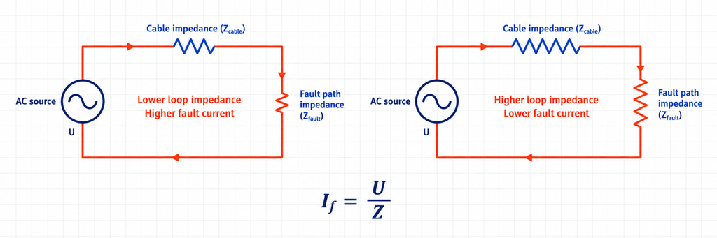
A high fault level at the board does not prove a high fault current at the end of a long cable. The outgoing conductors and return path add impedance. The minimum-current assessment also needs the relevant supply condition and fault path; a line-to-neutral fault and a line-to-earth fault cannot simply be treated as identical.
In a source-and-circuit model, fault current follows the relationship If = U / Z: current falls as the relevant loop impedance increases. For real design, select the correct voltage, impedance, source assumptions and correction factors rather than using that simplified relationship as an installation certificate.
The upper edge of the magnetic band is useful for a conservative initial screen. For the 20 A devices in the table, the reference values are 100 A for B, 200 A for C and 400 A for D. A minimum fault current below the upper edge does not prove that the breaker cannot operate magnetically; it means that the generic band alone does not establish assured magnetic operation.
If that initial screen fails, assess the full maximum operating-time boundary against the applicable disconnection requirement. Operation in another part of the curve might be acceptable for a particular duty, or it might be too slow. The answer comes from the circuit design and installation rules, not from the letter alone.
Generator and inverter-backed supplies deserve particular attention. Do not assume that their fault-current capability equals that of the normal utility supply. Where the source limits current, use its declared fault behavior and the intended protective arrangement.
A 20 A Equipment Circuit: Why C Can Be the Better Candidate
The following example is an illustrative screening exercise, not a completed installation design or a JUTRION customer project.
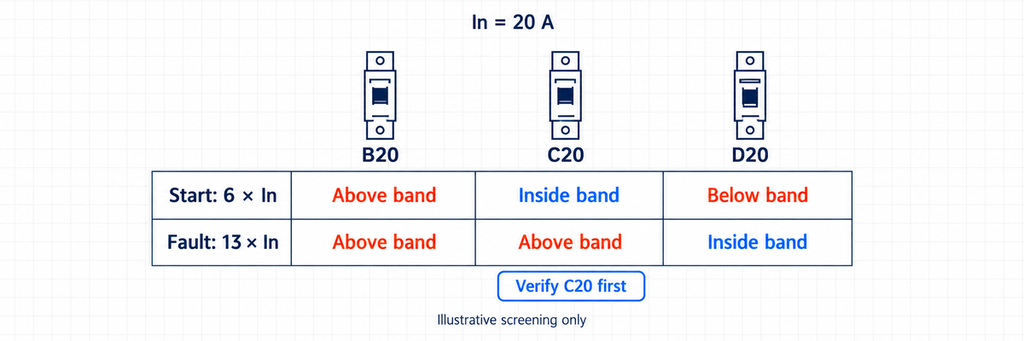
Assume an equipment circuit has a 14 A normal operating current. Its corrected cable capacity and protective-device conditions have already been checked for a 20 A MCB. For preliminary comparison, the recorded start is equivalent to approximately 120 A for 0.15 seconds, with its current definition suitable for comparison against the selected manufacturer’s characteristic. The calculated minimum relevant fault current is 260 A.
Convert those two currents into multiples of rated current:
Starting-current multiple = 120 A / 20 A = 6 × In
Minimum fault-current multiple = 260 A / 20 A = 13 × In
| Candidate | Start at 6 × In | Fault at 13 × In | Preliminary decision |
|---|---|---|---|
| B20 | Above the generic magnetic band’s upper edge | Above the magnetic band’s upper edge | Startup interruption is a concern; do not choose without contrary product-specific evidence |
| C20 | Inside the generic magnetic band | Above the magnetic band’s upper edge | The leading candidate for detailed curve verification |
| D20 | Below the generic magnetic band’s lower edge | Inside the generic magnetic band | Improved startup margin, but generic data does not establish assured magnetic fault operation |
C20 is the most useful candidate to investigate first, not an automatically approved choice. The start lies inside its magnetic band, so the exact 0.15-second behavior must be checked. The minimum fault current is above the generic C upper edge, making its fault-side screen more favorable than D.
Now use the actual product curve. Locate 6 × In on the horizontal axis and 0.15 seconds on the vertical axis. Compare the start envelope with the no-trip region and any manufacturer-specific starting-load guidance. Then assess the maximum operating time at the minimum relevant fault current, cable thermal withstand and required disconnection time.
Close the case with one of three outcomes:
- C20 passes both checks: retain C20 if the manufacturer’s data establishes ride-through of the complete start and acceptable fault disconnection. Confirm the remaining voltage, breaking-capacity and assembly requirements, then document the selected reference.
- C20 meets fault requirements but cannot tolerate the start: reduce simultaneous energization, apply equipment-approved inrush limiting or separate the starting loads. Reassess the changed start envelope against C20 before raising the curve.
- The equipment still needs D20: verify D20’s maximum operating time at 260 A against the circuit requirement. If it fails, revise the cable/source or protective arrangement; do not release D20 merely because it starts the equipment successfully.
The practical result is a C20-first verification path, with a defined alternative if startup fails. The example does not invent a manufacturer curve or claim that either candidate has passed a real test.
You can use the JUTRION MCB inrush and trip-curve checker to organize a preliminary band comparison. Treat its result as a screening aid; it does not evaluate the complete waveform, installation or manufacturer curve.
Use the Load Name as a Starting Point, Not the Verdict
Heaters, sockets and lighting
For the heater row in the application table, confirm that the load really is low-inrush. A heater assembly may also contain a transformer, fan or electronic controls; assess the complete equipment rather than the heating element alone.
Socket and lighting circuits need a closer look at their actual or permitted loads. An office socket circuit may supply printers, power supplies or equipment with significant starting demand. A lighting circuit may contain low-inrush lamps or a large simultaneously switched bank of electronic drivers. “Lighting” is not enough information to settle the curve.
For electronic lighting, the practical shortcut is the driver manufacturer’s breaker loading table, where available. It connects the number of drivers to particular ratings and curves. Otherwise, evaluate simultaneous energization and consider splitting or staggering the load before making the breaker less sensitive.
Motors, transformers and machine panels
Motor size alone does not establish the curve. A motor that accelerates quickly under a light load and the same motor driving a difficult mechanical start can require different starting-current assessments. Include starting method, acceleration time and permitted restart frequency.
A conventional MCB is not a substitute for every motor-protection function. A motor starter may need a coordinated short-circuit protective device, contactor and overload relay, or a motor-protection circuit breaker. Avoid increasing an MCB’s ampere rating to accommodate starting current while leaving the motor without suitable overload protection.
A transformer can create a short, asymmetric energization event that differs from an ordinary load increase. Use transformer-specific inrush data and protection recommendations rather than choosing D solely from transformer VA.
In a machine panel, include the start sequence. If the transformer, contactor coils, power supplies and drives all energize on the same main contactor, the breaker sees the combined event. Separating those events can be more effective than changing the characteristic of the whole feeder.
When a Curve Change Will Not Fix the Trip
Use the time and circumstances of the trip to direct the investigation. An immediate trip at energization suggests a different problem from a trip after an hour of normal operation, although timing alone is not a diagnosis.
For delayed trips, examine actual load current, cabinet temperature, device grouping and connections. The thermal region is temperature-dependent, as the ABB white paper explains. A warm, densely loaded board may need derating or improved thermal management; moving from B to C does not remove that issue.
For trips associated with a damaged cable, moisture or a repeatable equipment fault, correct the fault rather than suppressing the protective response. Repeatedly resetting a breaker without identifying the cause is not a commissioning method.
If the device is an RCBO, distinguish overcurrent operation from residual-current operation using the manufacturer’s indications and appropriate testing. Its B or C curve and its Type A, AC, F or B residual classification describe different functions. The RCBO selection guide explains the additional waveform, sensitivity and conductor decisions.
Likewise, an arc-fault event is not resolved by selecting D curve. Where arc protection is part of the installation, consult the AFDD working and selection guide for the separate protection function.
Inspection and electrical testing should be performed by qualified personnel using appropriate isolation and test procedures. Do not deliberately create a short circuit to see whether a newly selected curve works.
Confirm the Device, Not Just the Letter
Once the startup and disconnection behavior fit, confirm the remaining device ratings and interfaces:
- Rated current and corrected cable capacity: maintain overload protection for the actual installation and load duty.
- Voltage and AC/DC suitability: an AC characteristic discussion does not establish DC interruption capability.
- Breaking capacity: assess the maximum prospective fault current at the breaker location.
- Poles and terminals: match the circuit’s conductors, switching requirements and assembly connections.
- Product standard and market: confirm the declared ratings and approvals required by the destination.
- Upstream coordination: establish the intended fault containment for the exact device combination.
The Electrical Installation Guide’s breaker-characteristics reference distinguishes current, voltage, instantaneous settings and breaking ratings. These are separate checks; changing the curve cannot compensate for inadequate interruption capability.
Also distinguish selectivity from backup protection. Selectivity concerns which device disconnects; backup concerns the verified interruption performance of a protective combination. A higher upstream ampere rating or different curve does not prove either. Use the manufacturer’s coordination guidance and declared combination data.
Where a panel uses auxiliary contacts, shunt trips or other attachments, check the exact family interface. The circuit-breaker accessories guide is a separate resource for that matching task; the B, C or D designation does not establish accessory compatibility.
IEC 60898-1 addresses AC circuit-breakers for household and similar overcurrent protection. Industrial and North American applications may use different declared product frameworks. A familiar curve letter is not evidence that a device is approved for a North American branch circuit or any other particular market.
Frequently Asked Questions
Is a C curve MCB better than a B curve MCB?
Only when its characteristic fits the circuit better. C allows a higher magnetic operating range, which may help with starting loads, but B can be the better choice for low-inrush duties and circuits where fault-current availability is limited.
Can I replace B16 with C16 without changing the cable?
The ampere rating remains 16 A, but fault-disconnection performance changes. A qualified assessment must confirm the minimum relevant fault current, required operating time, cable protection, breaking capacity and board compatibility before replacement.
Why can a 20 A MCB carry more than 20 A briefly?
Rated current is not an instantaneous trip threshold. A thermal-magnetic device follows a time-current characteristic, allowing some short-duration overcurrent while responding to sustained overload and sufficiently high fault current.
Does D curve mean 10–14 or 10–20 times rated current?
10–20 × In is the familiar generic IEC-style D reference. Some product families declare narrower bands, including 10–14 × In. Use the exact device’s published characteristic for selection rather than transferring a manufacturer’s value to another product.
Will a D curve MCB stop a motor from tripping on startup?
It can help when verified normal starting current is operating the magnetic element. It will not solve sustained overload, a stalled motor, defective wiring or residual-current tripping. Confirm the cause and minimum fault-disconnection performance before changing to D, and retain suitable motor overload protection.
Before Specifying the Next Breaker
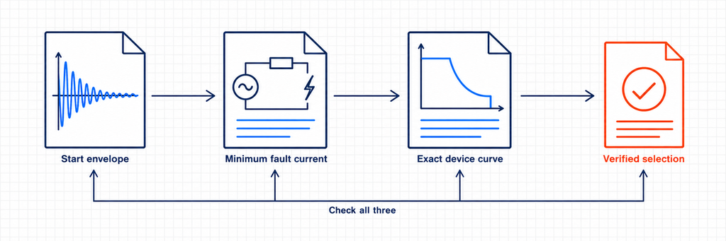
Keep three records together: the normal start envelope, the minimum relevant fault-current assessment, and the exact device characteristic. If all three support the choice, the curve has an engineering justification. If only startup has been checked, the selection is unfinished.
Explore the JUTRION miniature circuit-breaker range once those circuit conditions are established, then match the required rating, curve and configuration to an available product reference.
Technical References
