

MCB vs MCCB vs RCCB vs RCBO: What Is the Difference?
A short circuit at a socket and leakage through damaged insulation can require different protection, even when they occur on the same cable. That is why a distribution board may contain several kinds of circuit breaker.
The main difference between MCB, MCCB, RCCB and RCBO is the protection each provides. An MCB protects against overload and short circuit. An MCCB provides overcurrent protection for distribution duties that may need larger ratings, adjustable settings or greater fault-interruption capability. An RCCB detects residual current but has no integral overcurrent protection. An RCBO combines residual-current, overload and short-circuit protection.
For a contractor comparing boards, or a distributor comparing quotations, the useful question is therefore which functions each circuit needs. Buying four devices with the same ampere rating would not make them interchangeable.
MCB, MCCB, RCCB and RCBO Compared
| Comparison | MCB | MCCB | RCCB | RCBO |
|---|---|---|---|---|
| Full name | Miniature circuit breaker | Moulded case circuit breaker | Residual current operated circuit-breaker without integral overcurrent protection | Residual current operated circuit-breaker with integral overcurrent protection |
| Overload and short circuit | Yes | Yes, with the specified trip unit | No | Yes |
| Residual-current detection | No | Requires a suitable integrated function or associated arrangement | Yes | Yes |
| Protection adjustment | Usually fixed; select the current rating and curve | Fixed or adjustable, depending on trip unit | Usually fixed sensitivity; no overload setting | Usually fixed current, curve and sensitivity |
| Common IEC framework | 60898-1; some products also have 60947-2 ratings | 60947-2 | 61008-1 | 61009-1 |
| Typical position | Final circuit or small outgoing feeder | Incomer, distribution feeder or larger load | Often a circuit group, with separate overcurrent protection | Usually an individual final circuit |
| Main reason to choose it | Compact overcurrent protection | Required fault duty, adjustment or control features | Shared residual protection where group disconnection is acceptable | Combined protection with circuit-level fault isolation |
RCD is the family name. It means residual current device and includes both RCCBs and RCBOs. Informal terms such as RCB, and inconsistent use of ELCB, can make a quotation ambiguous. Identify the actual protection functions and product standard instead of assuming that every device described as an “earth leakage breaker” is the same.
What Happens During Overload, Short Circuit and Earth Leakage?
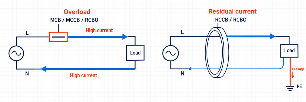
An overload is excessive current in an otherwise normal circuit. Connecting too many loads can heat the cable without creating a direct short circuit. A conventional thermal-magnetic MCB responds through its thermal element; an MCCB may use thermal-magnetic or electronic protection. An RCBO includes an overcurrent function too. An RCCB alone does not identify this balanced increase in load current.
A short circuit creates a much lower-impedance path. A line-to-neutral or line-to-line fault can produce current far above the normal load. The protective device must both initiate opening and safely interrupt that current. Its breaking capacity describes the interruption duty; the number beside the handle describing normal load current does not.
Residual current is an imbalance in the currents passing through the sensing arrangement. In a single-phase circuit, current leaving through line should return through neutral. If part returns by another path, an RCCB or RCBO can detect the difference. Three-phase devices evaluate the sum of the relevant live-conductor currents rather than comparing just one phase with neutral.
An earth fault can operate an overcurrent breaker when the fault path permits sufficient current. It is therefore inaccurate to say that an MCB can never clear an earth fault. The limitation is that an MCB has no dedicated residual-current sensing function and cannot replace required RCD protection.
Likewise, residual-current protection does not cover every electric-shock situation. A person contacting line and neutral may not create the imbalance needed to operate an RCD. Earthing, insulation and other protective measures remain part of the installation. The Electrical Installation Guide on additional RCD protection explains this distinction.
MCB vs MCCB: Where the Practical Difference Starts
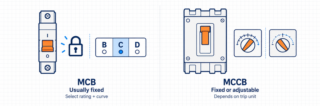
Choose an MCB when a fixed characteristic fits the circuit
An MCB is usually the straightforward choice for lighting, socket outlets and other smaller outgoing circuits. Its compact format and predefined operating characteristic make it convenient to repeat across a board. The design task is to match the current rating, operating curve, voltage and fault duty to each circuit.
Do not use 63 A or 100 A as a universal boundary between MCBs and MCCBs. Their ratings overlap. The scope of IEC 60898-1 includes AC breakers up to 125 A and short-circuit capacities up to 25 kA. These scope limits do not describe every available product.
Compare ampere and breaking-capacity ratings separately: two 32 A MCBs can have different short-circuit capabilities.
Choose an MCCB when the distribution duty needs more flexibility
An MCCB becomes attractive when the circuit requires a wider adjustment range, larger conductors, a different fault duty, or integration with the wider distribution system. Adjustable long-time and short-time functions, where provided, let the designer fit protection around load operation and downstream devices.
Frame size and protection setting are separate. A frame that accepts a particular maximum rating does not require the overload setting to equal that maximum. A fixed-trip MCCB, however, does not acquire adjustable protection simply because it has a moulded case. Compare the actual trip unit.
Auxiliary contacts, shunt trips and compatible motor operators may support status monitoring or remote operation. These accessories have different jobs; a shunt trip opens the breaker but does not remotely close it. The JUTRION circuit-breaker accessories guide explains the available functions and matching requirements.
The Parameters That Change the Choice
A useful comparison needs more than a list of typical ampere ranges. The following parameters answer different questions and should remain separate in a specification.
| Parameter | Meaning and operating condition | Example and decision consequence |
|---|---|---|
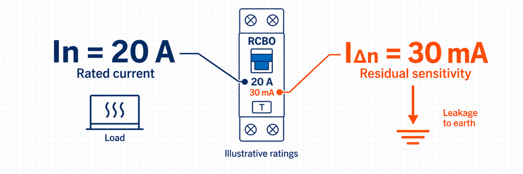
| Rated current, In | Declared current capability under specified conditions; temperature and installation affect usable loading | 32 A is a load-current rating. On an RCCB it does not mean that a 32 A overload trip is provided. |
| Overload setting, Ir | Adjustable long-time protection setting where the trip unit provides it | A feeder setting must protect the cable and support the load; choosing it from frame size alone can leave the cable inadequately protected. |
| Operational voltage, Ue | Voltage and AC/DC application for which performance is declared | A breaking-capacity value at 230 V cannot automatically be applied at 400 V or on DC. |
| Icn, Icu and Ics | Short-circuit performance ratings with different standard definitions and test duties | A 6 kA value must be compared with the fault level and its stated standard; it is not a 6,000 A normal-current rating. |
| Residual operating current, IΔn | Rated sensitivity of the residual-current function | 30 mA equals 0.03 A. It describes imbalance sensitivity, independently of a 20 A or 63 A load rating. |
| Curve and RCD type | B/C/D concern instantaneous overcurrent behavior; AC/A/F/B concern residual-current waveforms | A C-curve, Type A RCBO combines two separate characteristics. Changing its curve does not change its nominal residual sensitivity. |
| Poles and neutral | Which conductors are switched, sensed and overcurrent-protected | Check the diagram for 1P+N, 2P, 3P+N or 4P; similar labels do not establish identical neutral behavior. |
Read B, C and D as trip characteristics, not quality levels
Common IEC miniature-breaker instantaneous bands are approximately 3–5 × In for B, 5–10 × In for C, and 10–20 × In for D. For a 16 A device, that gives illustrative bands of 48–80 A, 80–160 A and 160–320 A respectively. These are operating bands, not a single guaranteed pickup point; the selected product curve controls.
A higher band can accommodate greater starting current, but it also demands sufficient fault current for rapid operation. Selecting D curve merely to stop nuisance tripping can worsen disconnection performance. Check the inrush duration and the available fault current together. The manufacturer’s explanation of breaker characteristics provides the rating context.
Compare breaking capacity at the actual installation point
Consider an illustrative board with a calculated prospective short-circuit current of 7.2 kA. A standalone 6 kA breaker does not satisfy that interruption duty; a correctly specified 10 kA device clears this initial capacity check. This comparison says nothing yet about cable protection or discrimination.
A lower-rated downstream device can sometimes be used with verified upstream backup protection. That requires a declared combination, not an assumption that any large MCCB makes every downstream breaker acceptable. The circuit-breaker selection guidance describes both routes.
For MCCBs, Icu is the ultimate short-circuit breaking rating and Ics describes service short-circuit performance. A large Icu alone does not establish the same service duty as an equally large Ics. Read both at the relevant voltage. An RCCB’s conditional short-circuit rating, meanwhile, depends on its specified associated protective device and must not be treated as an RCBO’s independent breaking capacity.
Select residual-current sensitivity and waveform capability together
Where additional protection is required, 30 mA is a common design choice. Values such as 100 mA and 300 mA serve other protection or coordination purposes and are not interchangeable substitutes for required 30 mA protection. A lower number alone does not make a complete selection.
Type AC detects sinusoidal AC residual current. Type A additionally detects pulsating DC. Type F addresses specified mixed-frequency conditions, while Type B includes smooth DC detection within its defined performance. Equipment with converters or drives can therefore change the required RCD type. Follow the equipment instructions and destination-market rules rather than choosing from load current alone. See the RCD waveform classifications for the technical distinction.
RCCB Plus MCBs or Individual RCBOs?
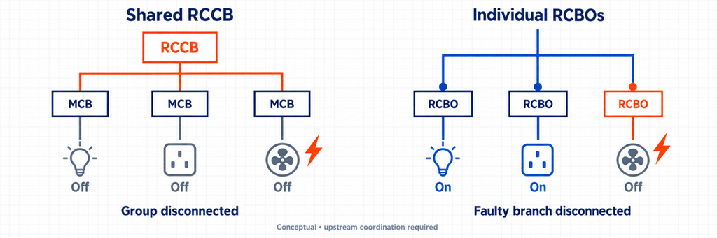
Use individual RCBOs when losing unrelated circuits would be disruptive. A shared RCCB with separate MCBs remains a practical arrangement when group disconnection is acceptable and the protection is properly coordinated. Compare the consequence of a fault before comparing component prices.
The extra device cost can be worthwhile for refrigeration, payment equipment or lighting that must remain available while another circuit is investigated. The workshop example below shows how this changes the board arrangement.
Check the shared RCCB’s total loading. The combined branch load can exceed its carrying capacity without exceeding any single MCB rating. Branch MCBs alone therefore do not automatically protect it against overload; the complete arrangement must provide the required protection.
Normal leakage is another difference. Electronic equipment can contribute protective-conductor current during healthy operation. Grouping many circuits under one RCCB combines their residual-current behavior at that device. Individual RCBOs separate the groups, but do not repair faulty insulation or remove the need to account for normal leakage.
Neutral routing must follow the selected arrangement. A neutral shared across separately protected groups can undermine operation and cause unwanted trips. Changing to RCBOs can therefore involve more than replacing devices on the DIN rail.
For an existing installation, a qualified electrician should assess the board and wiring before conversion. For a new panel, the JUTRION RCBO selection guide takes the next step into residual type, sensitivity and conductor configuration.
A Small Workshop: Comparing Two Protection Arrangements
The following is an illustrative design comparison, not a completed customer installation. A workshop has separate branches for a bench heater, general sockets, lighting and a fixed machine. The owner wants a heater fault to have as little effect as possible on the rest of the workshop.
Start with the heater branch. Assume a 4.6 kW single-phase resistive load at 230 V, power factor approximately one, and a cable with a corrected current-carrying capacity of 27 A. The load current is:
Ib = P / U = 4,600 W / 230 V = 20 A.
Here Ib is design current, P is electrical input power and U is supply voltage. A proposed 25 A protective rating passes the initial relationship 20 A ≤ 25 A ≤ 27 A between load, breaker and corrected cable capacity. A 32 A selection fails this check because it exceeds the stated cable capacity. Device derating and the remaining conductor-protection conditions still need checking.
If residual-current protection is required, both arrangements below retain the proposed 25 A branch rating. The required sensitivity and waveform type are selected separately.
Arrangement one uses a shared RCCB and branch MCBs. The heater has its own overcurrent protection, but a qualifying residual-current fault can also remove supply from the workshop’s other branches. This arrangement conflicts with the owner’s stated continuity preference if all four branches share that RCCB.
Arrangement two assigns an RCBO to each appropriate final circuit. This better supports independent disconnection. The heater’s load calculation carries across unchanged; what changes is where residual-current protection operates. The machine branch must still follow its equipment requirements, particularly if it includes a drive.
The upstream feeder may use an MCCB if its load, adjustment or fault duty justifies one. It does not need to be an MCCB merely because the building is called a workshop. Nor does the feeder’s rating prove that it will remain closed during every downstream fault.
For this owner’s continuity requirement, choose individual RCBOs for the suitable final circuits. Keep the machine’s equipment-specific requirements and upstream coordination in the design.
What the Product Standard Does—and Does Not—Tell You
The standard identifies the product’s testing framework; the installation rules determine how it may be used. A standards number does not supply the design current, prospective fault current or circuit arrangement for a particular project.
A device can have ratings under more than one standard. Use the rating corresponding to the applicable duty rather than choosing whichever kA figure looks largest. The IEC catalogue references at the end identify the documents consulted, including the 2024 editions for IEC 60947-2, IEC 61008-1 and IEC 61009-1.
Check the applicable edition or national adoption in the product documentation. For North American projects, confirm the required local listing and installation rules; an IEC reference alone does not establish acceptance.
Keep the Rest of the Board Working
The remaining system question is selectivity: will the device nearest the fault clear it while upstream protection stays closed? A larger upstream current rating does not prove this. Verify the manufacturer’s selectivity data for the chosen devices and fault level. Backup protection addresses interruption capability and is a different question from selectivity. The breaker coordination guidance explains the distinction.
Residual-current devices in series need their own coordination assessment, including sensitivity, time behavior and waveform compatibility. Two identical 30 mA devices in series do not establish selective operation. Use declared RCD coordination guidance rather than guessing from the nominal ratings.
Finally, this comparison covers overcurrent and residual-current protection. Transient surge protection has a separate role, explained in the JUTRION SPD guide. Adding an RCBO does not remove that design question.
When comparing the next panel quotation, follow one outgoing circuit from its load back to the supply. Identify which device clears each fault and which healthy circuits lose power when it operates. That makes the differences between MCB, MCCB, RCCB and RCBO tangible before the equipment is ordered.
Frequently Asked Questions
Can an RCCB replace an MCB?
No. An RCCB detects residual current but does not provide overload or short-circuit protection. It needs suitable separate overcurrent protection. An RCBO combines both functions when its ratings suit the circuit.
Is an MCCB always better than an MCB?
No. An MCB is often the practical choice for a smaller final circuit. An MCCB is useful when the duty calls for different ratings, adjustable protection or additional control functions. Choose according to the circuit, not the size of the enclosure.
Do I still need an MCB if I use an RCBO?
An appropriately selected RCBO already includes branch-circuit overload and short-circuit protection, so another MCB is not normally needed just to duplicate those functions. Upstream feeder protection and coordination still apply.
What is the difference between 63 A and 30 mA on an RCCB?
63 A is its rated current-carrying capability under declared conditions. 30 mA is its rated residual operating current. Neither marking gives an RCCB integral overload protection; that requires a separate protective device.
Will individual RCBOs stop the whole board from tripping?
They can isolate a residual-current fault to one branch, reducing disruption to healthy circuits. They do not guarantee that upstream protection stays closed. That depends on the fault and the coordination of the complete arrangement.
Technical References
